EP0012879A2 - Einmal in ihrer Laufrichtung umkehrbare Farbbandkassette für einen Stossdrucker - Google Patents
Einmal in ihrer Laufrichtung umkehrbare Farbbandkassette für einen Stossdrucker Download PDFInfo
- Publication number
- EP0012879A2 EP0012879A2 EP79104867A EP79104867A EP0012879A2 EP 0012879 A2 EP0012879 A2 EP 0012879A2 EP 79104867 A EP79104867 A EP 79104867A EP 79104867 A EP79104867 A EP 79104867A EP 0012879 A2 EP0012879 A2 EP 0012879A2
- Authority
- EP
- European Patent Office
- Prior art keywords
- cartridge
- ribbon
- finger
- reel
- positioning
- Prior art date
- Legal status (The legal status is an assumption and is not a legal conclusion. Google has not performed a legal analysis and makes no representation as to the accuracy of the status listed.)
- Granted
Links
Images
Classifications
-
- B—PERFORMING OPERATIONS; TRANSPORTING
- B41—PRINTING; LINING MACHINES; TYPEWRITERS; STAMPS
- B41J—TYPEWRITERS; SELECTIVE PRINTING MECHANISMS, i.e. MECHANISMS PRINTING OTHERWISE THAN FROM A FORME; CORRECTION OF TYPOGRAPHICAL ERRORS
- B41J33/00—Apparatus or arrangements for feeding ink ribbons or like character-size impression-transfer material
- B41J33/14—Ribbon-feed devices or mechanisms
- B41J33/54—Ribbon-feed devices or mechanisms for ensuring maximum life of the ribbon
- B41J33/56—Ribbon adjusted transversely
-
- B—PERFORMING OPERATIONS; TRANSPORTING
- B41—PRINTING; LINING MACHINES; TYPEWRITERS; STAMPS
- B41J—TYPEWRITERS; SELECTIVE PRINTING MECHANISMS, i.e. MECHANISMS PRINTING OTHERWISE THAN FROM A FORME; CORRECTION OF TYPOGRAPHICAL ERRORS
- B41J32/00—Ink-ribbon cartridges
-
- B—PERFORMING OPERATIONS; TRANSPORTING
- B41—PRINTING; LINING MACHINES; TYPEWRITERS; STAMPS
- B41J—TYPEWRITERS; SELECTIVE PRINTING MECHANISMS, i.e. MECHANISMS PRINTING OTHERWISE THAN FROM A FORME; CORRECTION OF TYPOGRAPHICAL ERRORS
- B41J33/00—Apparatus or arrangements for feeding ink ribbons or like character-size impression-transfer material
- B41J33/14—Ribbon-feed devices or mechanisms
- B41J33/40—Ribbon-feed devices or mechanisms with arrangements for reversing the feed direction
- B41J33/42—Ribbon-feed devices or mechanisms with arrangements for reversing the feed direction manually
Definitions
- the present invention relates to a ribbon cartridge structure for impact printers and, more particularly, to a reversible single-use ribbon cartridge.
- the present invention relates to a device which allows maximum use of the ribbon surface while minimizing repeated strikes of the same area or overlapping; that is, it allows the use of vertically adjacent areas of the ribbon for impact printing without vertical ribbon offset in the printer.
- the device comprises a ribbon cartridge which can be introduced into reception means provided in an impact printer provided with ribbon drive means, said ribbon cartridge being reversible only once.
- the cartridge consists of a housing in which two spools are mounted in rotation, to be able to pass a certain amount of tape from one to the other.
- the housing has a two-position positioning finger which can be irreversibly transferred from its initial position to its second position.
- This ribbon cartridge is intended to cooperate with receiving means provided in the impact printer, which have means exclusively receiving the positioning finger placed in its initial position which corresponds to the driving of the ribbon from said first reel to said second reel, and means receiving exclusively said positioning finger in its second position which corresponds to the drive of the ribbon from said second reel to said first reel, and this after turning the cartridge over.
- the ribbon can only be driven for a single initial passage when the positioning finger is in its initial position and for a second passage or passage in the opposite direction, only when the positioning finger is in its second position. Since the transfer of the positioning finger from its initial position to its second position is irreversible, it cannot be brought back to its initial position. Thus, the device receiving the cartridge positioning finger in the printer can no longer receive said cartridge when the ribbon of the latter has already been passed twice through the machine since a third pass would require the centralization of the ribbon from the first reel to the. second coil, which is impossible due to the irreversible blocking of said positioning finger in its second position.
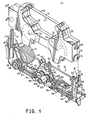
- Figure 1 shows the ribbon cartridge 10 of the present invention which is designed to operate in conjunction with a ribbon driver 14 of a high speed printer.
- the ribbon 11 is contained in a cartridge case 10.
- a part 12 of the ribbon is wound on a supply reel (or supply reel) and a part 13 of the ribbon is wound on a take-up reel (or take-up reel).
- the housing 10 is shown disengaged from the drive device 14 and these two assemblies are shown in the vertical position or loading / unloading position of the ribbon cartridge.
- two pairs of cartridge positioning fingers 15, 15 'and 15''and15''' are respectively received and guided by two pairs of vertical rails 16 and 17 in the device drive, each pair of rails 16 and 17 defining a passage 18, 19 could receive and guide the positioning fingers of the cartridge as will be described later.
- the positioning fingers are guided by the passages 18 and 19 in holes 70 formed in flexible cartridge blocking tongues 20 and 20 '.
- the commitment positioning fingers in the holes 70 of the flexible tongues 20 and 20 ′ block the cartridge in the operating position.
- the tabs 20 and 20 ' can be manually moved away from the cartridge so that the fingers are released from their corresponding holes 70.
- the loading and unloading of the cartridge is done in the vertical position shown in Figure 1, after which the tape drive can be tilted to its horizontal operating position.
- the cartridge 10 When the cartridge 10 is locked in the operating position in the drive device 14, the assembly formed by these two elements is in horizontal position relative to the plate (not shown) of a printer. In this position, the ribbon 15 is entrainé before a printing sheet (not shown) carried by the plate. Any conventional impact printing device (such as a printing wheel and its striking assembly, a printing character bar or a printing ball), will be driven against the ribbon 11 to apply it against the printing medium in order to print the selected character.
- a stepping motor 37 drives a pinion 38 in rotation which in turn drives a toothed wheel 39 on which is fixed a driving pulley 40.
- the driving pulley 40 drives a belt drive 41 of the take-up reel, which is guided by pulleys 42, 43, 44, 45, 46 and 47.
- the belt 41 is also guided by a movable pulley 48; to which is connected a spring 50 which will be described later, and by a pulley 49 which is fixed to a drive pinion 51.
- a drive belt 52 of the supply reel which is made of the same practically inextensible material as that used for the belt 41, is carried and guided by a series of pulleys 53 to 58 corresponding to the pulleys 42 to 47 carrying and guiding the belt of the take-up reel.
- a movable pulley 59 performs a function equivalent to that of the movable pulley 48.
- This pulley 59 is also connected to the spring 50.
- the pinion 51 drives a pinion 60 which, in turn, drives a pinion 61.
- a pulley 62 is fixed to the pinion 61 and driven by the latter and in turn drives the belt 52 of the supply reel.
- the pulleys 49 and 62 are identical, except that the pulley 62 which is associated with the drive belt of the supply reel, has a diameter slightly smaller than that of the pulley 49.
- the drive belt 52 of the take-up reel will be driven at a speed slightly lower than that of the drive belt 41 of the take-up reel. Since the belts 41 and 52 respectively drive the take-up reel 13 and the take-up reel 12 by non-sliding contact with their peripheries, the part of the tape 11 leaving the take-up reel 12 will move at a constant speed slightly lower than that of the part of the ribbon 11 winding on the take-up reel 13. This speed difference ensures the application of a constant tension to the ribbon 11. This speed difference remains constant and consequently, the slight tension applied to the ribbon will also remain constant regardless of the quantity of ribbon wound on the supply reel 12 or the take-up reel 13.
- the spring 50 and its associated pulleys 48 and 59 catch any slack in the drive belts 41 and 52 which could be caused by changes in the amount of ribbon wound on the reels 12 and 13. While the others pulleys are fixed, pulleys 48 and 59 are mobile, 9 that is to say they move according to the modifications of the quantity of the ribbon wound on the receiving and supply reels. In this way, the length of the spring 50 remains constant but its position shifts to compensate for the changes in the quantities of ribbon wound on the reels 12 and 13.
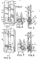
- the cartridge has four positioning fingers 15 to 15 "'. Three of these fingers, namely 15' to 15"', are fixed while finger 15 has an eccentric base 71 which can be placed in two positions. In the first position which is that shown in Figure 1, the widest part of the base of the positioning finger is turned to the side of the left edge of the cartridge. In this position, the narrowest part of the base. of the positioning finger 15 is out of contact with the rail 72 of the pair of rails 16. This case is shown in more detail in FIG.
- the edge 73 of the rail 72 is released from the narrowest part of the base of the positioning finger 15 and the latter can move downward in the passage 18 formed by the pair of rails 16 and arrive at the position where it comes to cooperate with the tongue 20 as described previously with reference to FIG. 1.
- the ribbon drive device 14 drives the coil 12 around its axis 74 so that this coil acts as a supply coil and that the coil 13 rotating on its axis 75 acts as a receiving coil.
- the edge 77 of the ribbon 11 will be in the uppermost portion and thus will be in a position adjacent to the impact printing means, which allows the upper half of the ribbon 11 adjacent to the edge 77 d be struck during the printing operation.
- the cartridge can be turned over once on itself for an additional passage of the ribbon . This is done as follows: the cartridge is removed from the drive device by releasing the tab 20 and lifting the cartridge. The eccentric base 71 of the positioning finger 15 is then manually rotated by 180 °, which definitively locks the positioning finger in the position of FIG. 5. The device allowing the rotation of this positioning finger and its blocking in the. second position will be described later with reference to Figures 3, 4, 6 and 7. The positioning finger 15 being locked in this second position, the widest side of the eccentric base 71 is now to the right side of the cartridge.
- the cartridge can no longer be inserted into the receiving means formed by the two pairs of vertical rails since the rail 72 will prohibit the downward movement of the positioning finger in the passage 18 defined by the pair of rails. vertical 16.
- the positioning finger 15 locked in this second position can be inserted without difficulty into the receiving means formed on the other side of the drive device in the pair of vertical rails 17 defining the passage 19, given that the rail 76 will be adjacent to the smallest side of the eccentric base 71 of the positioning finger 15.
- the latter can easily slide from below in the passage 19 to engage in a hole (not shown) formed in the flexible tongue 20 ′ which is the equivalent of the hole 70 of the flexible tongue 20.
- the axis 75 becomes the axis of the coil e debtor and the axis 74 becomes the axis of the take-up reel.
- the second half of the ribbon 11 that is to say the half adjacent to the edge 78, will now be in the upper position, that is to say in the position of printing and all character strokes will be applied to this half of the ribbon.
- the ribbon is passed twice through the machine, one half, that is to say the upper half being used during a first pass while the other half, the lower half, is used during a second pass.
- the second position of the positioning finger 15 is irreversible, it cannot be reintroduced into the receiving means formed by the pair of vertical rails 16 for a third passage of the ribbon.
- FIG. 3 there is shown the positioning finger 15 in its initial position relative to the pair of vertical rails 16. Narrow 80 and wide pawls 83 forming part of the finger 15 are inserted into a hole 81 formed in a hub 82 of the cartridge housing 10. When the positioning finger is thus placed in its initial position, the wide pawl 83 is adjacent to an inner groove 84 of the hub 82. Since the pawl 83 is wider than the groove 84, it does not cannot enter it and there is no lock.
Landscapes
- Impression-Transfer Materials And Handling Thereof (AREA)
Applications Claiming Priority (2)
| Application Number | Priority Date | Filing Date | Title |
|---|---|---|---|
| US06/000,233 US4264223A (en) | 1979-01-02 | 1979-01-02 | Reversible ribbon cartridge for a high speed impact printer |
| US233 | 1979-01-02 |
Publications (3)
| Publication Number | Publication Date |
|---|---|
| EP0012879A2 true EP0012879A2 (de) | 1980-07-09 |
| EP0012879A3 EP0012879A3 (en) | 1981-03-25 |
| EP0012879B1 EP0012879B1 (de) | 1983-06-22 |
Family
ID=21690542
Family Applications (1)
| Application Number | Title | Priority Date | Filing Date |
|---|---|---|---|
| EP79104867A Expired EP0012879B1 (de) | 1979-01-02 | 1979-12-04 | Einmal in ihrer Laufrichtung umkehrbare Farbbandkassette für einen Stossdrucker |
Country Status (9)
| Country | Link |
|---|---|
| US (1) | US4264223A (de) |
| EP (1) | EP0012879B1 (de) |
| JP (1) | JPS5593485A (de) |
| AU (1) | AU524151B2 (de) |
| BR (1) | BR7908620A (de) |
| CA (1) | CA1127106A (de) |
| DE (1) | DE2965771D1 (de) |
| ES (1) | ES487053A1 (de) |
| IT (1) | IT1165424B (de) |
Cited By (4)
| Publication number | Priority date | Publication date | Assignee | Title |
|---|---|---|---|---|
| US4359288A (en) * | 1980-06-16 | 1982-11-16 | International Business Machines Corporation | Single pass ribbon cartridge for impact printers having means to prevent incorrect insertion |
| DE3536402A1 (de) * | 1984-10-12 | 1986-04-17 | Ricoh Co., Ltd., Tokio/Tokyo | Farbbandkassette |
| US4836698A (en) * | 1986-09-08 | 1989-06-06 | Brother Kogyo Kabushiki Kaisha | Invertible ribbon cartridge |
| DE3741363A1 (de) * | 1987-12-07 | 1989-06-15 | Triumph Adler Ag | Traeger eines farbbandes fuer schreib- und aehnliche maschinen |
Families Citing this family (16)
| Publication number | Priority date | Publication date | Assignee | Title |
|---|---|---|---|---|
| DE3164817D1 (en) * | 1980-03-13 | 1984-08-23 | Nec Corp | A cartridge for an inked ribbon for an impact printer |
| US4496255A (en) * | 1980-09-04 | 1985-01-29 | Nec Corporation | Invertible multiple-pass ribbon cartridge having two capstans |
| JPS5857960A (ja) * | 1981-10-02 | 1983-04-06 | Canon Inc | インク供給装置 |
| JPS59111883A (ja) * | 1982-12-17 | 1984-06-28 | Canon Inc | インクリボンカセツト装着機構 |
| USD284389S (en) | 1983-11-30 | 1986-06-24 | Advanced Matrix Technology, Inc. | Ribbon cartridge |
| US4568210A (en) * | 1984-03-30 | 1986-02-04 | Wang Laboratories, Inc. | Reversible ribbon cartridge |
| EP0194694B1 (de) * | 1985-03-15 | 1992-09-30 | Hitachi, Ltd. | Bandkassette für Drucker |
| US4629346A (en) * | 1985-04-22 | 1986-12-16 | Surti Tyrone N | Printer ribbon cassette |
| EP0299312A3 (de) * | 1987-07-13 | 1989-05-03 | Caracteres S.A. | Zubehör für Drucker, insbesondere für Büro-Schreibmaschinen |
| JP2635049B2 (ja) * | 1987-07-24 | 1997-07-30 | 株式会社日立製作所 | 熱転写記録装置 |
| DE3741360A1 (de) * | 1987-12-07 | 1989-06-15 | Triumph Adler Ag | Aufnahmevorrichtung fuer einen traeger eines farbbandes in schreib- oder aehnlichen maschinen |
| ZA929834B (en) * | 1991-12-19 | 1993-06-23 | Telkor Pty Ltd | Print ribbon cassettes. |
| GB2272669B (en) * | 1992-11-20 | 1996-09-25 | Neopost Ltd | Printing apparatus |
| USD360220S (en) | 1993-06-17 | 1995-07-11 | Taurus Impressions, Inc. | Tape cartridge for debossment stamper for logo impression |
| USD362459S (en) | 1993-06-17 | 1995-09-19 | Taurus Impressions, Inc. | Tape cartridge for debossment stamper for character impression |
| US7706733B2 (en) * | 2007-04-10 | 2010-04-27 | Xerox Corporation | Mechanism for transfix member with idle movement |
Family Cites Families (13)
| Publication number | Priority date | Publication date | Assignee | Title |
|---|---|---|---|---|
| US609476A (en) * | 1898-08-23 | Type-writing machine | ||
| US2203168A (en) * | 1936-07-09 | 1940-06-04 | Florence B Long | Printing mechanism |
| US2278009A (en) * | 1940-09-30 | 1942-03-31 | Royal Typewriter Co Inc | Typewriting machine |
| US2986260A (en) * | 1957-12-20 | 1961-05-30 | Ibm | Ribbon mechanism |
| US2940577A (en) * | 1959-02-20 | 1960-06-14 | Marion I Smallwood | Teletype machine ribbon control |
| US3110215A (en) * | 1962-01-15 | 1963-11-12 | Eastman Kodak Co | Magazine orientation indicator |
| US3481445A (en) * | 1965-10-14 | 1969-12-02 | Ibm | Cartridge ribbon supply |
| US3650378A (en) * | 1968-07-13 | 1972-03-21 | Ricoh Kk | Faulty insertion preventive device for cartridges |
| DE2123172A1 (de) * | 1971-05-11 | 1972-11-23 | Anker-Werke Ag, 4800 Bielefeld | Einrichtung zur Ausnutzung des Farbbandes bei Druckwerken für Büromaschinen oder dergl |
| JPS5043724U (de) * | 1973-08-15 | 1975-05-02 | ||
| DE2415265A1 (de) * | 1974-03-29 | 1975-10-16 | Buettner Ag Franz | Kassette fuer farbband fuer schreibende maschinen |
| DE2515899C3 (de) * | 1975-04-11 | 1978-03-02 | Standard Elektrik Lorenz Ag, 7000 Stuttgart | Zweifarbenumschaltvorrichtung für Farbbandkassetten |
| US4160605A (en) * | 1977-09-26 | 1979-07-10 | Pitney Bowes Deutschland Gmbh | Ink ribbon box |
-
1979
- 1979-01-02 US US06/000,233 patent/US4264223A/en not_active Expired - Lifetime
- 1979-11-13 CA CA339,718A patent/CA1127106A/en not_active Expired
- 1979-11-16 JP JP14787479A patent/JPS5593485A/ja active Granted
- 1979-12-04 EP EP79104867A patent/EP0012879B1/de not_active Expired
- 1979-12-04 DE DE7979104867T patent/DE2965771D1/de not_active Expired
- 1979-12-07 AU AU53616/79A patent/AU524151B2/en not_active Ceased
- 1979-12-18 IT IT28118/79A patent/IT1165424B/it active
- 1979-12-19 ES ES487053A patent/ES487053A1/es not_active Expired
- 1979-12-28 BR BR7908620A patent/BR7908620A/pt not_active IP Right Cessation
Cited By (5)
| Publication number | Priority date | Publication date | Assignee | Title |
|---|---|---|---|---|
| US4359288A (en) * | 1980-06-16 | 1982-11-16 | International Business Machines Corporation | Single pass ribbon cartridge for impact printers having means to prevent incorrect insertion |
| DE3536402A1 (de) * | 1984-10-12 | 1986-04-17 | Ricoh Co., Ltd., Tokio/Tokyo | Farbbandkassette |
| US4836698A (en) * | 1986-09-08 | 1989-06-06 | Brother Kogyo Kabushiki Kaisha | Invertible ribbon cartridge |
| DE3741363A1 (de) * | 1987-12-07 | 1989-06-15 | Triumph Adler Ag | Traeger eines farbbandes fuer schreib- und aehnliche maschinen |
| US4955737A (en) * | 1987-12-07 | 1990-09-11 | Ta Triumph Adler Aktiengesellschaft | Holder for a ribbon for typewriters or similar machines |
Also Published As
| Publication number | Publication date |
|---|---|
| JPS579955B2 (de) | 1982-02-24 |
| EP0012879A3 (en) | 1981-03-25 |
| AU5361679A (en) | 1980-07-10 |
| DE2965771D1 (en) | 1983-07-28 |
| BR7908620A (pt) | 1980-09-02 |
| EP0012879B1 (de) | 1983-06-22 |
| AU524151B2 (en) | 1982-09-02 |
| US4264223A (en) | 1981-04-28 |
| IT1165424B (it) | 1987-04-22 |
| IT7928118A0 (it) | 1979-12-18 |
| JPS5593485A (en) | 1980-07-15 |
| ES487053A1 (es) | 1980-06-16 |
| CA1127106A (en) | 1982-07-06 |
Similar Documents
| Publication | Publication Date | Title |
|---|---|---|
| EP0012879B1 (de) | Einmal in ihrer Laufrichtung umkehrbare Farbbandkassette für einen Stossdrucker | |
| FR2601626A1 (fr) | Imprimante, cassette de ruban pour imprimante et procede de montage de cassette | |
| FR2525532A1 (de) | ||
| EP1295727B1 (de) | Thermische Druckvorrichtung zum Öffnen und Verriegeln | |
| FR2540436A1 (fr) | Imprimante d'etiquettes a configurations selectives du mouvement de serie d'etiquettes | |
| EP0012878B1 (de) | Farbbandantrieb, z.B. in einem Schnelldrucker | |
| FR2470683A1 (fr) | Cassette a ruban encreur pour imprimante serie | |
| EP0184234A1 (de) | Mehrfarbiger Drucker | |
| FR2561174A1 (fr) | Imprimante thermique | |
| EP0128866A1 (de) | Vorrichtung zum Zuführen von Bogen für ein Druckgerät oder eine Schreibmaschine | |
| FR2499024A1 (fr) | Etiqueteuse a main | |
| EP1113933A1 (de) | Kassette für bandförmiges verbrauchsmaterial, insbesondere für eine vorrichtung zur behandlung von berechtigunsscheinen | |
| EP0013294A2 (de) | Mehrfachtypenscheibendruckwerk für Schreibmaschine oder Drucker | |
| EP0013293A2 (de) | Farbbandzufuhrvorrichtung für einen Drucker mit frühzeitiger Erkennung des Bandendes | |
| FR2468468A1 (fr) | Dispositif a ruban encreur du type cassette | |
| FR2520297A1 (fr) | Procede et appareil pour brouiller le texte inscrit sur des rubans encreurs utilisables une fois dans des machines a ecrire et analogues | |
| EP0030624B1 (de) | Farbbandkassette und ihre Verriegelungsvorrichtung an einer Schreibmaschine | |
| WO1997046976A1 (fr) | Dispositif pour delivrer des tickets formes par des tronçons de bande | |
| EP0020212B1 (de) | Druckeinrichtung mit einem Mechanismus zur relativen Querbewegung eines auf einer Druckwalze abgeordneten Aufzeichnungsträger in Bezug auf einen Druckkopf | |
| FR2647246A1 (fr) | Dispositif pour la presentation d'affiches contenues dans des cartouches, et cartouches pour la mise en oeuvre de ce dispositif | |
| FR2769868A1 (fr) | Systeme d'imprimante | |
| FR2624057A1 (fr) | Recipient formant logement pour un support de ruban encreur dans une machine a ecrire ou analogue | |
| EP0013300B1 (de) | Druckelement mit in einer Kassette angeordneter Typenscheibe | |
| FR2644107A1 (fr) | Cassette de ruban encreur pour imprimante | |
| FR2639287A1 (fr) | Entraineur de papier pour imprimante |
Legal Events
| Date | Code | Title | Description |
|---|---|---|---|
| PUAI | Public reference made under article 153(3) epc to a published international application that has entered the european phase |
Free format text: ORIGINAL CODE: 0009012 |
|
| AK | Designated contracting states |
Designated state(s): BE CH DE FR GB NL |
|
| PUAL | Search report despatched |
Free format text: ORIGINAL CODE: 0009013 |
|
| AK | Designated contracting states |
Designated state(s): BE CH DE FR GB NL |
|
| RHK1 | Main classification (correction) |
Ipc: B41J 33/42 |
|
| 17P | Request for examination filed |
Effective date: 19810331 |
|
| GRAA | (expected) grant |
Free format text: ORIGINAL CODE: 0009210 |
|
| AK | Designated contracting states |
Designated state(s): BE CH DE FR GB NL |
|
| REF | Corresponds to: |
Ref document number: 2965771 Country of ref document: DE Date of ref document: 19830728 |
|
| PLBE | No opposition filed within time limit |
Free format text: ORIGINAL CODE: 0009261 |
|
| STAA | Information on the status of an ep patent application or granted ep patent |
Free format text: STATUS: NO OPPOSITION FILED WITHIN TIME LIMIT |
|
| 26N | No opposition filed | ||
| PGFP | Annual fee paid to national office [announced via postgrant information from national office to epo] |
Ref country code: DE Payment date: 19891227 Year of fee payment: 11 |
|
| PGFP | Annual fee paid to national office [announced via postgrant information from national office to epo] |
Ref country code: NL Payment date: 19891231 Year of fee payment: 11 |
|
| PGFP | Annual fee paid to national office [announced via postgrant information from national office to epo] |
Ref country code: CH Payment date: 19900327 Year of fee payment: 11 |
|
| PG25 | Lapsed in a contracting state [announced via postgrant information from national office to epo] |
Ref country code: CH Effective date: 19901231 |
|
| PG25 | Lapsed in a contracting state [announced via postgrant information from national office to epo] |
Ref country code: NL Effective date: 19910701 |
|
| NLV4 | Nl: lapsed or anulled due to non-payment of the annual fee | ||
| REG | Reference to a national code |
Ref country code: CH Ref legal event code: PL |
|
| PG25 | Lapsed in a contracting state [announced via postgrant information from national office to epo] |
Ref country code: DE Effective date: 19910903 |
|
| REG | Reference to a national code |
Ref country code: FR Ref legal event code: GC |
|
| PGFP | Annual fee paid to national office [announced via postgrant information from national office to epo] |
Ref country code: FR Payment date: 19911108 Year of fee payment: 13 |
|
| PGFP | Annual fee paid to national office [announced via postgrant information from national office to epo] |
Ref country code: BE Payment date: 19911118 Year of fee payment: 13 |
|
| PGFP | Annual fee paid to national office [announced via postgrant information from national office to epo] |
Ref country code: GB Payment date: 19911129 Year of fee payment: 13 |
|
| REG | Reference to a national code |
Ref country code: GB Ref legal event code: 732 |
|
| REG | Reference to a national code |
Ref country code: FR Ref legal event code: TP |
|
| PG25 | Lapsed in a contracting state [announced via postgrant information from national office to epo] |
Ref country code: GB Effective date: 19921204 |
|
| PG25 | Lapsed in a contracting state [announced via postgrant information from national office to epo] |
Ref country code: BE Effective date: 19921231 |
|
| BERE | Be: lapsed |
Owner name: LEXMARK INTERNATIONAL INC. Effective date: 19921231 |
|
| GBPC | Gb: european patent ceased through non-payment of renewal fee |
Effective date: 19921204 |
|
| PG25 | Lapsed in a contracting state [announced via postgrant information from national office to epo] |
Ref country code: FR Effective date: 19930831 |
|
| REG | Reference to a national code |
Ref country code: FR Ref legal event code: ST |