EP0012923A1 - Fermeture antivol - Google Patents
Fermeture antivol Download PDFInfo
- Publication number
- EP0012923A1 EP0012923A1 EP19790105081 EP79105081A EP0012923A1 EP 0012923 A1 EP0012923 A1 EP 0012923A1 EP 19790105081 EP19790105081 EP 19790105081 EP 79105081 A EP79105081 A EP 79105081A EP 0012923 A1 EP0012923 A1 EP 0012923A1
- Authority
- EP
- European Patent Office
- Prior art keywords
- insert
- locking device
- balls
- pin
- cup
- Prior art date
- Legal status (The legal status is an assumption and is not a legal conclusion. Google has not performed a legal analysis and makes no representation as to the accuracy of the status listed.)
- Granted
Links
- 238000003780 insertion Methods 0.000 claims description 5
- 230000037431 insertion Effects 0.000 claims description 5
- 238000010276 construction Methods 0.000 description 5
- 238000012986 modification Methods 0.000 description 4
- 230000004048 modification Effects 0.000 description 4
- 230000000717 retained effect Effects 0.000 description 3
- 230000014759 maintenance of location Effects 0.000 description 2
- 238000000926 separation method Methods 0.000 description 2
- 238000013475 authorization Methods 0.000 description 1
- 230000009977 dual effect Effects 0.000 description 1
- 230000000694 effects Effects 0.000 description 1
- 238000003754 machining Methods 0.000 description 1
- 238000004519 manufacturing process Methods 0.000 description 1
Images
Classifications
-
- E—FIXED CONSTRUCTIONS
- E05—LOCKS; KEYS; WINDOW OR DOOR FITTINGS; SAFES
- E05B—LOCKS; ACCESSORIES THEREFOR; HANDCUFFS
- E05B73/00—Devices for locking portable objects against unauthorised removal; Miscellaneous locking devices
- E05B73/0017—Anti-theft devices, e.g. tags or monitors, fixed to articles, e.g. clothes, and to be removed at the check-out of shops
-
- Y—GENERAL TAGGING OF NEW TECHNOLOGICAL DEVELOPMENTS; GENERAL TAGGING OF CROSS-SECTIONAL TECHNOLOGIES SPANNING OVER SEVERAL SECTIONS OF THE IPC; TECHNICAL SUBJECTS COVERED BY FORMER USPC CROSS-REFERENCE ART COLLECTIONS [XRACs] AND DIGESTS
- Y10—TECHNICAL SUBJECTS COVERED BY FORMER USPC
- Y10T—TECHNICAL SUBJECTS COVERED BY FORMER US CLASSIFICATION
- Y10T24/00—Buckles, buttons, clasps, etc.
- Y10T24/46—Pin or separate essential cooperating device therefor
- Y10T24/4604—Pin or separate essential cooperating device therefor having distinct guiding, holding, or protecting means for penetrated portion
- Y10T24/4605—Means detachable from or flaccidly connected to pin [e.g., hatpin type]
- Y10T24/4609—Means detachable from or flaccidly connected to pin [e.g., hatpin type] including relatively movable guiding, holding, or protecting components or surfaces
- Y10T24/4611—Means detachable from or flaccidly connected to pin [e.g., hatpin type] including relatively movable guiding, holding, or protecting components or surfaces having operator for moving holding component or surface
- Y10T24/4614—Moves slidably guided, nonself-biasing, holding component
-
- Y—GENERAL TAGGING OF NEW TECHNOLOGICAL DEVELOPMENTS; GENERAL TAGGING OF CROSS-SECTIONAL TECHNOLOGIES SPANNING OVER SEVERAL SECTIONS OF THE IPC; TECHNICAL SUBJECTS COVERED BY FORMER USPC CROSS-REFERENCE ART COLLECTIONS [XRACs] AND DIGESTS
- Y10—TECHNICAL SUBJECTS COVERED BY FORMER USPC
- Y10T—TECHNICAL SUBJECTS COVERED BY FORMER US CLASSIFICATION
- Y10T24/00—Buckles, buttons, clasps, etc.
- Y10T24/50—Readily interlocking, two-part fastener requiring either destructive or tool disengagement
-
- Y—GENERAL TAGGING OF NEW TECHNOLOGICAL DEVELOPMENTS; GENERAL TAGGING OF CROSS-SECTIONAL TECHNOLOGIES SPANNING OVER SEVERAL SECTIONS OF THE IPC; TECHNICAL SUBJECTS COVERED BY FORMER USPC CROSS-REFERENCE ART COLLECTIONS [XRACs] AND DIGESTS
- Y10—TECHNICAL SUBJECTS COVERED BY FORMER USPC
- Y10T—TECHNICAL SUBJECTS COVERED BY FORMER US CLASSIFICATION
- Y10T70/00—Locks
- Y10T70/50—Special application
- Y10T70/5004—For antitheft signaling device on protected article
-
- Y—GENERAL TAGGING OF NEW TECHNOLOGICAL DEVELOPMENTS; GENERAL TAGGING OF CROSS-SECTIONAL TECHNOLOGIES SPANNING OVER SEVERAL SECTIONS OF THE IPC; TECHNICAL SUBJECTS COVERED BY FORMER USPC CROSS-REFERENCE ART COLLECTIONS [XRACs] AND DIGESTS
- Y10—TECHNICAL SUBJECTS COVERED BY FORMER USPC
- Y10T—TECHNICAL SUBJECTS COVERED BY FORMER US CLASSIFICATION
- Y10T70/00—Locks
- Y10T70/70—Operating mechanism
- Y10T70/7051—Using a powered device [e.g., motor]
- Y10T70/7057—Permanent magnet
Definitions
- the present invention relates as indicated to an anti-theft locking device, and more particularly to a locking device particularly adapted to be used in a system for preventing unauthorized removal of articles from department stores, boutiques, or the like.
- the locking device is securely mounted in an identification tag, with the lock being securely attached to articles of merchandise in such a manner that the lock can be opened or separated only by the use of a special tool which can be conveniently located at the checkout point in the department store or similar establishment.
- the lock tightly frictionally engages a pin which extends through the protected article , with the actuation of the tool permitting the pin to be released and the lock and tag removed from the article for normal purchased items.
- the construction of the tag and the complete system permits an alarm system to be actuated at an exit point or points in the store thereby notifying the store operators of the unauthorized removal of the article from the premises.
- Locking devices similar in purpose to the locking device of the present invention are disclosed in U. S. Patents 3,858,280 to Martin A. J. Martens and 3,911,534 to Henry J. Martens et al. Reference is specifically made to these patents for a complete understanding of the anti-theft system and the specific construction of the identification tag with which the locking device of the present invention is employed. It should be noted in this regard that-the identification tag has been disclosed in the present application drawing and will- be referred to hereinbelow only for a full understanding of the present invention, with the construction of the tag forming no part thereof. Similarly, the detaching tool by means of which the locking device can be separated from the article secured thereto forms no part of the present invention, and reference is made to U. S. Patent 3,911,534 which discloses a detaching tool which can be satisfactorily employed with the locking device of the present invention.
- Removal of the pin was effected by placing the fastening device adjacent the detaching tool which, when actuated, e-lectromagnetically moved the insert, formed of magnetizable material, upwardly in the housing thereby permitting the retaining balls to move upwardly along the cam surface of the ring and out of tight frictional engagement with the pin.
- the pin and tag with the fastening device could then be removed and separately stored for reuse.
- a primary object of the present invention is to provide a locking device which can be quickly and easily secured to the articles to be protected, while simultaneously providing a locking arrangement which precludes separation of the pin from the lock without a special detaching tool.
- a further object of the invention is to provide such a locking device in which substantial savings of both material and labor are achieved.
- the insert is substantially shorter and provided with only a single, longitudinal bore.
- a . cup is frictionally retained within a opening provided therefor in the bottom of the housing, and the retaining balls are loosely positioned in the bottom or closed end of the cup, and separated from the insert by a flanged washer.
- the cup serves the dual purpose of both retaining the insert and the balls, and providing a cam surface along which the balls can upwardly travel during insertion of the pin:
- the balls When the pin is in position and released, the balls tightly frictionally engage the pin due to spring tension placed on the upper end of -the insert, with the spring pressure acting through the insert and the flanged washer and causing the balls - to be biased radially inwardly into tight frictional engagement with the pin.
- a further object of the invention is to provide a locking device which not only requires a special tool to open or separate, but additionally is essentially _ tamper-proof. The turning of the housing within its mounted position in the identification tag has no effect on the lock since the housing and pin rotate together.
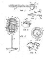
- Figure 1 illustrates the locking device of the present invention, generally indicated at 10, mounted in a tag assembly generally indicated at-12.
- the tag assembly forms no part of the present invention and can be of comparable construction to the tag assembly disclosed in U.S. Patent 3,911,534.
- a tubular extension 14 is formed, and the locking device is formed with a radially extending flange 16, best seen in Figure 2, which extends into an annular recess 18 provided therefor in the tubular extension 14. In this manner, the locking device can be mounted in the tag assembly.
- the portion 20 of the.tag. is provided with a recess in which to receive the cup 22 of the lock, shown in dashed lines in Figure 1 and shown in enlarged form in Figure 2.
- the pin 24 is shown in a locked position in Figure 1, with an article 26 being shown fragmentarily in Figure 1 between the pin 24_and the locking device.
- a detaching tool (not shown) is positioned adjacent the end of the locking device opposite the pin thereby permitting the pin 24 to be withdrawn and the article removed from the tag assembly and lock. If the article 26 to which the tag assembly and lock are attached is attempted to be removed from the premises without authorization, a transmitting circuit contained with the tag 12 functions to actuate detecting equipment normally positione at each exit of the store thereby to signal the unauthorized removal of the article.
- the locking device 10 includes a housing or cap 30 which is preferably molded of plastic material.
- the cap 30 is formed with a central opening 32.and a relatively enlarged bottom opening 34.
- the otherwise closed end of the cap is provided with an opening 36 through which the pin can extend in the event the pii length is such that it is not fully accommodated with the cap.
- An insert generally indicated at 40 is loosely mounted within the cap, and a spring 42 extends around a slightly reduced diameter portion 44 of the insert, with the opposite end of the spring contacting a flat annular surface 46 of the cap.
- the spring 42 continually biases the insert 40 downwardly, in the orientation of the locking device as shown in Figure 2.
- the insert 40 further indicates a main body portion 47 formed with a single longitudinal opening 48 through which the pin shank 50 can extend, Positioned below the insert is a flanged washer 52, and below the flanged washer there are three retaining balls commonly designated at 54.
- the insert, flanged washer and balls are housed within the cup 22 the open end of which is formed with a radially outwardly extending flange 56 the outer diameter of which is slightly greater than the diameter of the enlarged opening 34 of the cap.
- the balls 54 normally rest on the bottom of the cup when the locking device is separated from the pin.
- the main body portion 47 of the insert 40 is tapered so as not to interfere during movement with the side walls of the ⁇ cup 22, which are correspondingly tapered. However, close tolerances are not necessary.
- the flanged washer 52 is formed with a plurality of downwardly depending arcuately spaced flanges commonly designated at 60 the purpose of which is to keep the retaining balls spaced and separated when the pin shank is inserted in the lock. The balls are thus unable to ride up and over an adjacent ball, which would inhibit or prevent pin retention in the lock.
- the balls 54 rest on the bottom of the cup 22.
- the cup 22 is formed with an opening 64 in the bottom wall thereof through which the pin shank 50 can extend, with the flanged washer 52 being formed with a similar opening 66 which is aligned both with the opening 64 and the longitudinal opening 48 formed in the insert 40.
- the cup 22 due to the curved side wall portions adjacent the bottom of the cup,-provides a cam surface for the balls, which can move upwardly along such surface when the pin shank 50 is inserted into the locking device.
- the balls are positioned between the flanges 60 of the washer 52 as above described.
- the balls are moved apart so as to provide an opening therebetween for the pin shank 50 which, when continued to be moved upward, extends through the opening 66 in the flanged washer and the opening 48 in the insert.
- Both the flanged washer 52 and the insert 40 are likewise moved upwardly away from the closed end of the cup, with the diameter of the main body portion of the insert at the top thereof being slightly less than the diameter of the opening 32 of the cap so as to permit the insert to extend upwardly within such opening.
- Such upward movement is of course against the bias of the spring 42, which continually applies spring pressure to the insert and consequently to the flanged washer and retaining balls.
- the tag assembly 12 includes a leg portion 70 which is hinged to the remainder of the tag body, with the leg 70 carrying the pin 24.
- the entire leg is removed when the locking device is opened, thereby avoiding the separation of the pin from the lock so as to facilitate reuse of the tag and lock.
- the assembly of the locking device can be quickly and easily effected.
- the balls 54 are placed at the bottom of the cup 22, with the flanged washer 52 next being placed in the cup above the balls.
- the insert 40 is then placed in the cup above the flanged washer, and the spring 42 positioned around the reduced diameter portion 44 of the insert. All of these parts are then moved into the cap, with the radial flange 56 of the cup being forced upwardly into the opening 34 at the bottom end of the housing. A tight frictional engagement of the cup within the housing is thereby achieved, and all parts are in their assembled position.
- the locking device can then be inserted in the tubular extension 14 of the tag assembly 12 as above described, thereby readying the lock for receiving the pin 50.
- the invention is extremely simple in construction and easy to assemble.
- the smaller dimension and reduced machining of the insert, and the low manufacturing costs of the cup 22 and flanged washer 52 result in an inexpensive locking device, without, however, detracting from the efficient and positive locking achieved thereby.
- flanges comparable to flanges 60 on washer 52 can be provided at the periphery of the bottom end of the insert.
- the washer can be eliminated, with the bottom of the insert contacting the retaining balls directly.
- the washer can also be eliminated by forming the cup with a plurality of radially inwardly diverted and longitudinally extending projections on the_tapered cam surface for arcuately spacing the balls within the cup.
- Figs. 5 and 6 The modifications just referred to are shown in Figs. 5 and 6, respectively.
- Fig. 5 which shows the insert 40 in inverted form, downwardly and inwardly directed flanges commonly designated at 80 are formed onthe periphery of the bottom surface 82 of the insert, with the edges of adjacent flanges defining therebetween channels commonly designated at 84.
- the balls 54 during insertion of the pin shank 50 through the opening 64 are thus confined to movement radially outwardly in the channels for engagement with the cam surfaces formed by the side walls of the cup, for pin retention under the bias of spring 42, as previously described.
- Fig. 6 is atop plan view of the cup 22, showing arcuately spaced projections commonly designated at 90 formed therein.
- the projections 90 extend longitudinally from adjacent'the bottom of the cup to a position above the uppermost position of travel of the bottom of the insert 48, whereby the balls 54 are at all times movable radially in channels 92 between the projections 90.
- the camming of the balls against the .side walls of the cup is as previously described, with the pin shank 50 extending upwardly into the cup through opening 64.
Landscapes
- Burglar Alarm Systems (AREA)
- Lock And Its Accessories (AREA)
- Control Of Vending Devices And Auxiliary Devices For Vending Devices (AREA)
Priority Applications (1)
| Application Number | Priority Date | Filing Date | Title |
|---|---|---|---|
| AT79105081T ATE4338T1 (de) | 1978-12-20 | 1979-12-10 | Diebstahlsichere schliessvorrichtung. |
Applications Claiming Priority (2)
| Application Number | Priority Date | Filing Date | Title |
|---|---|---|---|
| US05/971,165 US4221025A (en) | 1978-12-20 | 1978-12-20 | Anti-theft locking device |
| US971165 | 1978-12-20 |
Publications (2)
| Publication Number | Publication Date |
|---|---|
| EP0012923A1 true EP0012923A1 (fr) | 1980-07-09 |
| EP0012923B1 EP0012923B1 (fr) | 1983-07-27 |
Family
ID=25518006
Family Applications (1)
| Application Number | Title | Priority Date | Filing Date |
|---|---|---|---|
| EP19790105081 Expired EP0012923B1 (fr) | 1978-12-20 | 1979-12-10 | Fermeture antivol |
Country Status (5)
| Country | Link |
|---|---|
| US (1) | US4221025A (fr) |
| EP (1) | EP0012923B1 (fr) |
| AT (1) | ATE4338T1 (fr) |
| CA (1) | CA1113699A (fr) |
| DE (1) | DE2966009D1 (fr) |
Cited By (10)
| Publication number | Priority date | Publication date | Assignee | Title |
|---|---|---|---|---|
| EP1669528A3 (fr) * | 2004-12-09 | 2009-12-02 | Johan Skjellerup | Système de sécurité pour éviter l'élimination non autorisée de marchandise |
| US7750806B1 (en) | 2007-08-08 | 2010-07-06 | Johan Skjellerup | Magnetic security tag assembly |
| US8223022B2 (en) | 2004-12-09 | 2012-07-17 | Johan Skjellerup | Security tag assembly |
| WO2012060855A3 (fr) * | 2010-10-19 | 2012-08-09 | Sensormatic Electronics, LLC | Procédé et étiquette de système de sécurité à deux pinces |
| US8590348B1 (en) | 2011-10-31 | 2013-11-26 | Braebum Asset Holdings, LLC. | Security tag assembly |
| US8590349B2 (en) | 2012-03-20 | 2013-11-26 | Braebum Asset Holdings, LLC. | Security tag assembly |
| WO2018011601A1 (fr) * | 2016-07-14 | 2018-01-18 | Mainetti (Uk) Ltd | Étiquette |
| US10096217B2 (en) | 2016-05-11 | 2018-10-09 | Braeburn Asset Holdings, Llc | Security system and security tag assembly |
| CN112523633A (zh) * | 2020-12-10 | 2021-03-19 | 维沃移动通信有限公司 | 电子设备 |
| EP3997763A4 (fr) * | 2019-07-10 | 2023-07-19 | MyPauze Holding AB | Boîtier de dispositif électronique portable |
Families Citing this family (63)
| Publication number | Priority date | Publication date | Assignee | Title |
|---|---|---|---|---|
| SE423938B (sv) * | 1980-04-11 | 1982-06-14 | Bo Ollie Gustavsson | Stoldskyddselement |
| USD271848S (en) | 1980-12-08 | 1983-12-20 | Tcherneshoff Associates, Inc. | Tamper-proof fastening device for tags and the like |
| USD273177S (en) | 1983-06-27 | 1984-03-27 | Tcherneshoff Associates, Inc. | Tamper-proof fastening device for tags and the like |
| US4527310A (en) * | 1983-07-22 | 1985-07-09 | I. D. Engineering, Inc. | Secure release apparatus for anti-theft fastening device |
| US4523356A (en) * | 1984-02-27 | 1985-06-18 | Security Tag Systems, Inc. | Ball clutch mechanism with two sets of balls in separate radial planes |
| US4670950A (en) * | 1985-05-13 | 1987-06-09 | Monarch Marking Systems, Inc. | Theft-deterrent tag |
| US4780592A (en) * | 1985-09-17 | 1988-10-25 | Bias Forschungs-und Entwicklungs-Labor fur Angewandte Strahltechnik GmbH | Apparatus for cutting workpieces by means of a high-energy beam |
| SE451906B (sv) * | 1986-02-13 | 1987-11-02 | Intermodulation & Safety Syste | Larmanordning innefattande en av tva delar bestaende larmbricka vilken i ett aktivt lege avger en akustisk signal da delarna fjermar sig fran varandra |
| US4745664A (en) * | 1986-10-17 | 1988-05-24 | Antonson Security Denmark A/S | Lock for securing a mark especially onto a textile article |
| US5022243A (en) * | 1989-09-06 | 1991-06-11 | Star Lock Company | Latching system |
| US5027630A (en) * | 1989-03-22 | 1991-07-02 | Star Lock Company | Door latch with lock and release for vending machines and the like |
| US4900182A (en) * | 1989-03-22 | 1990-02-13 | Stillwagon Applied Techonology Incorporated | Lock and release apparatus |
| US5272894A (en) * | 1989-03-22 | 1993-12-28 | Star Lock Systems, Inc. | Fractional-rotation latching system with retrofit capability |
| US5467619A (en) * | 1989-03-22 | 1995-11-21 | Star Lock Systems, Inc. | Post latching systems |
| US4993245A (en) * | 1989-03-28 | 1991-02-19 | Frank Ott | Security tag for use on articles of clothing and the like |
| EP0405155A1 (fr) * | 1989-06-01 | 1991-01-02 | Ott, Frank | Etiquette de sécurité réutilisable |
| US5269161A (en) * | 1989-09-06 | 1993-12-14 | Star Lock Systems, Inc. | Latching system |
| US5077872A (en) * | 1990-08-10 | 1992-01-07 | Antonson Security Denmark A/S | Antitheft device |
| IT1240918B (it) * | 1990-05-10 | 1993-12-23 | Costa Emilio Int Plast | Sigillo antifurto per articoli di commercio presentanti porzioni astiformi |
| US5140836A (en) * | 1991-09-19 | 1992-08-25 | Security Tag Systems, Inc. | Theft-deterrent device including clamp |
| US5367289A (en) * | 1991-11-27 | 1994-11-22 | Sensormatic Electronics Corporation | Alarm tag for an electronic article surveillance system |
| SE9202510L (sv) * | 1992-09-01 | 1994-03-02 | Faergklaemman Svenska Ab | Stöldskyddselement för stöldbegärliga varor |
| US5426419A (en) * | 1993-01-14 | 1995-06-20 | Sensormatic Electronics Corporation | Security tag having arcuate channel and detacher apparatus for same |
| US5337459A (en) * | 1993-03-16 | 1994-08-16 | Security Tag Systems, Inc. | Magnetically releasable clamp |
| US5497639A (en) | 1994-11-15 | 1996-03-12 | Link Enterprises, Inc. | Non-cuttable device for attachment of shoplifting detection tag |
| SE514204C2 (sv) * | 1996-07-03 | 2001-01-22 | Faergklaemman Ab | Stöldskyddsanordning, låselement till en stöldskyddsanordning samt en frigöringsanordning till en stöldskyddsanordning |
| US6255950B1 (en) | 1999-10-19 | 2001-07-03 | Sensormatic Electronics Corporation | Tack assembly for electronic article surveillance tags |
| US6449991B1 (en) | 2000-04-12 | 2002-09-17 | Sensormatic Electronics Corporation | One part theft deterrent device |
| US6832499B2 (en) | 2000-08-14 | 2004-12-21 | Star Lock Systems, Inc. | Vandal resistant T-handle assembly |
| US6564597B1 (en) | 2000-08-14 | 2003-05-20 | Star Lock Systems, Inc. | Vandal resistant T-handle assembly |
| JP4252713B2 (ja) * | 2000-08-31 | 2009-04-08 | センサーマチック・エレクトロニックス・コーポレーション | 盗難防止装置 |
| AU2002225925A1 (en) | 2000-10-26 | 2002-05-06 | Alpha Security Products, Inc. | Eas tag holder |
| ES1049269Y (es) * | 2001-06-04 | 2002-03-16 | Mehr S L | Cierre de caja de seguridad |
| USD468223S1 (en) | 2001-09-26 | 2003-01-07 | Alpha Security Products, Inc. | Anti-shoplifting EAS tag holder |
| USD466037S1 (en) | 2002-02-07 | 2002-11-26 | Alpha Security Products, Inc. | EAS tag holder |
| USD466427S1 (en) | 2002-02-07 | 2002-12-03 | Alpha Security Products, Inc. | EAS tag holder |
| US7652574B2 (en) * | 2002-04-08 | 2010-01-26 | Sayegh Adel O | Article surveillance tag having a vial |
| JP2006509267A (ja) * | 2002-04-08 | 2006-03-16 | オデー サイェフ アデル | 金属クリップを備える商品監視タグ |
| USD474417S1 (en) | 2002-05-31 | 2003-05-13 | Alpha Security Products, Inc. | Theft deterrent tag |
| USD478833S1 (en) | 2002-05-31 | 2003-08-26 | Alpha Security Products, Inc. | Theft deterrent tag |
| USD492215S1 (en) | 2003-06-02 | 2004-06-29 | Universal Surveillance Corpporation | Electronic article surveillance device |
| US20060070410A1 (en) * | 2003-08-29 | 2006-04-06 | Arthur Fuss | Product anti-theft device |
| GB0329665D0 (en) * | 2003-12-22 | 2004-01-28 | Itw Ltd | Long-necked seal |
| US20050200485A1 (en) * | 2004-02-09 | 2005-09-15 | One World Technologies Limited | Article containing anti-theft device |
| US7342495B2 (en) * | 2004-06-02 | 2008-03-11 | Sayegh Adel O | Integrated theft deterrent device |
| GB0504776D0 (en) * | 2005-03-08 | 2005-04-13 | Itw Ltd | Security seal |
| USD566598S1 (en) | 2006-09-27 | 2008-04-15 | Sayegh Adel O | Electronic article surveillance (EAS) tag with swiveling lanyard attachment |
| USD567128S1 (en) | 2006-09-27 | 2008-04-22 | Sayegh Adel O | Electronic article surveillance (EAS) tag device with a lanyard |
| US8044806B2 (en) * | 2006-10-19 | 2011-10-25 | Sayegh Adel O | Security tag with engaging element |
| US7808390B2 (en) * | 2007-01-05 | 2010-10-05 | Adel Sayegh | Security tag having a swiveling engagement |
| US8117874B2 (en) * | 2008-08-07 | 2012-02-21 | Checkpoint Systems, Inc. | Theft deterrent device including a spring washer |
| USD599693S1 (en) | 2008-08-27 | 2009-09-08 | Sayegh Adel O | Theft deterrent tag having crossing lanyard for use with articles |
| FR2944307B1 (fr) * | 2009-04-14 | 2013-09-06 | Thoonsen Trading | Dispositif antivol pour articles de vente |
| USD628924S1 (en) | 2009-05-05 | 2010-12-14 | Universal Surveillance Corporation | Theft deterrent tag having lanyards for use with articles |
| USD628923S1 (en) | 2009-05-05 | 2010-12-14 | Universal Surveillance Corporation | Electronic article surveillance device having lanyards for use with articles |
| US20110283754A1 (en) * | 2010-05-24 | 2011-11-24 | Checkpoint Systems, Inc. | Security device for ring products |
| US9238519B2 (en) | 2012-03-14 | 2016-01-19 | Louis J. Zimmel | Unitary lanyard and base for electronic surveillance tag |
| WO2013192390A1 (fr) * | 2012-06-20 | 2013-12-27 | Checkpoint Systems, Inc. | Dispositif de sécurité de marchandises et procédés associés |
| FR3007783B1 (fr) * | 2013-06-28 | 2015-07-10 | Fors France | Dispositif antivol destine a etre attache a un article en vente libre |
| USD760058S1 (en) * | 2015-03-26 | 2016-06-28 | Jose Laxamana | Appliance leg security lock |
| CN105065887A (zh) * | 2015-08-11 | 2015-11-18 | 李娜 | 一种安装结构及设备 |
| WO2019141781A1 (fr) * | 2018-01-18 | 2019-07-25 | Zliide Technologies Aps | Étiquette de sécurité pour article vêtement |
| WO2021007362A1 (fr) | 2019-07-08 | 2021-01-14 | Sensormatic Electronics, LLC | Étiquette de sécurité à embrayage à 3 billes pouvant être libérée par un ensemble de déverrouillage |
Citations (6)
| Publication number | Priority date | Publication date | Assignee | Title |
|---|---|---|---|---|
| DE113767C (fr) * | ||||
| CH30719A (fr) * | 1904-05-24 | 1905-01-15 | A Beguelin Henry | Bouton de sûreté pour épingles |
| DK10762C (da) * | 1908-04-21 | Oscar Clauson-Kaas | Anordning til Fastholdelse af Naale. | |
| FR612368A (fr) * | 1925-03-07 | 1926-10-22 | Dispositif de freinage et d'arrêt à friction sur câble, corde, ou l'équivalent | |
| CH335255A (de) * | 1955-03-24 | 1958-12-31 | Holmberg Arne | Verriegelungsvorrichtung |
| US3911534A (en) * | 1974-10-30 | 1975-10-14 | I D Engineering Inc | Anti-theft fastening device |
Family Cites Families (3)
| Publication number | Priority date | Publication date | Assignee | Title |
|---|---|---|---|---|
| US1472681A (en) * | 1923-02-28 | 1923-10-30 | Levi J Roy | Pin and like securing device |
| US2826855A (en) * | 1956-11-23 | 1958-03-18 | Edmond L Troccia | Fish hook devices |
| US3858280A (en) * | 1972-11-17 | 1975-01-07 | I D Engineering Inc | Fastening clip |
-
1978
- 1978-12-20 US US05/971,165 patent/US4221025A/en not_active Expired - Lifetime
-
1979
- 1979-12-10 AT AT79105081T patent/ATE4338T1/de not_active IP Right Cessation
- 1979-12-10 DE DE7979105081T patent/DE2966009D1/de not_active Expired
- 1979-12-10 EP EP19790105081 patent/EP0012923B1/fr not_active Expired
- 1979-12-14 CA CA342,107A patent/CA1113699A/fr not_active Expired
Patent Citations (7)
| Publication number | Priority date | Publication date | Assignee | Title |
|---|---|---|---|---|
| DE113767C (fr) * | ||||
| DK10762C (da) * | 1908-04-21 | Oscar Clauson-Kaas | Anordning til Fastholdelse af Naale. | |
| CH30719A (fr) * | 1904-05-24 | 1905-01-15 | A Beguelin Henry | Bouton de sûreté pour épingles |
| FR612368A (fr) * | 1925-03-07 | 1926-10-22 | Dispositif de freinage et d'arrêt à friction sur câble, corde, ou l'équivalent | |
| CH335255A (de) * | 1955-03-24 | 1958-12-31 | Holmberg Arne | Verriegelungsvorrichtung |
| US3911534A (en) * | 1974-10-30 | 1975-10-14 | I D Engineering Inc | Anti-theft fastening device |
| DE2548546A1 (de) * | 1974-10-30 | 1976-05-06 | I D Engineering Inc | Befestigungsvorrichtung und werkzeug zum loesen derselben |
Cited By (11)
| Publication number | Priority date | Publication date | Assignee | Title |
|---|---|---|---|---|
| EP1669528A3 (fr) * | 2004-12-09 | 2009-12-02 | Johan Skjellerup | Système de sécurité pour éviter l'élimination non autorisée de marchandise |
| US8223022B2 (en) | 2004-12-09 | 2012-07-17 | Johan Skjellerup | Security tag assembly |
| US7750806B1 (en) | 2007-08-08 | 2010-07-06 | Johan Skjellerup | Magnetic security tag assembly |
| WO2012060855A3 (fr) * | 2010-10-19 | 2012-08-09 | Sensormatic Electronics, LLC | Procédé et étiquette de système de sécurité à deux pinces |
| US8590348B1 (en) | 2011-10-31 | 2013-11-26 | Braebum Asset Holdings, LLC. | Security tag assembly |
| US8590349B2 (en) | 2012-03-20 | 2013-11-26 | Braebum Asset Holdings, LLC. | Security tag assembly |
| US10096217B2 (en) | 2016-05-11 | 2018-10-09 | Braeburn Asset Holdings, Llc | Security system and security tag assembly |
| US10332372B2 (en) | 2016-05-11 | 2019-06-25 | Braeburn Asset Holdings, Llc | Security system and security tag assembly |
| WO2018011601A1 (fr) * | 2016-07-14 | 2018-01-18 | Mainetti (Uk) Ltd | Étiquette |
| EP3997763A4 (fr) * | 2019-07-10 | 2023-07-19 | MyPauze Holding AB | Boîtier de dispositif électronique portable |
| CN112523633A (zh) * | 2020-12-10 | 2021-03-19 | 维沃移动通信有限公司 | 电子设备 |
Also Published As
| Publication number | Publication date |
|---|---|
| US4221025A (en) | 1980-09-09 |
| DE2966009D1 (en) | 1983-09-01 |
| EP0012923B1 (fr) | 1983-07-27 |
| CA1113699A (fr) | 1981-12-08 |
| ATE4338T1 (de) | 1983-08-15 |
Similar Documents
| Publication | Publication Date | Title |
|---|---|---|
| US4221025A (en) | Anti-theft locking device | |
| US4903383A (en) | Anti-theft fastening | |
| US3858280A (en) | Fastening clip | |
| US3974581A (en) | Anti-theft fastening device and tool for releasing same | |
| US3947930A (en) | Anti-theft fastening device and tool for releasing same | |
| EP1222351B1 (fr) | Ensemble rivet pour etiquettes de surveillance electronique d'articles | |
| US4506415A (en) | Security seal and tag holder | |
| US3983725A (en) | Padlock case | |
| EP1121300B1 (fr) | Dispositif anti-vol pour bouteilles | |
| US5161838A (en) | Locking assembly | |
| US3911534A (en) | Anti-theft fastening device | |
| EP0132531B1 (fr) | Dispositif de fixation pour un disque de détection de vol | |
| JPH0237098Y2 (fr) | ||
| US6052876A (en) | Versatile attachment mechanism for theft deterrent tags | |
| EP0811740B1 (fr) | Récipient verrouillable pour disques compacts et similaires | |
| FI922771A0 (fi) | Tjuvsaeker kombination av behaollare och lock. | |
| WO1994028381A1 (fr) | Procede et appareil pour desarmer automatiquement des bombes aerosols d'autodefense | |
| US3848440A (en) | Padlock case | |
| HK101393A (en) | Magnetic lock closure | |
| US20090064734A1 (en) | Surveillance device | |
| EP3468406B1 (fr) | Fixation pour bagage à fermeture à glissière | |
| US3733037A (en) | Closure means for pneumatic carrier | |
| US3971269A (en) | Fastening clip and tool for releasing same | |
| US7501957B1 (en) | Tamperproof bottle locking system | |
| US3149745A (en) | Self-locking snap-on container cap |
Legal Events
| Date | Code | Title | Description |
|---|---|---|---|
| PUAI | Public reference made under article 153(3) epc to a published international application that has entered the european phase |
Free format text: ORIGINAL CODE: 0009012 |
|
| AK | Designated contracting states |
Designated state(s): AT BE CH DE FR GB IT LU NL SE |
|
| 17P | Request for examination filed |
Effective date: 19810108 |
|
| ITF | It: translation for a ep patent filed | ||
| GRAA | (expected) grant |
Free format text: ORIGINAL CODE: 0009210 |
|
| AK | Designated contracting states |
Designated state(s): AT BE CH DE FR GB IT LU NL SE |
|
| REF | Corresponds to: |
Ref document number: 4338 Country of ref document: AT Date of ref document: 19830815 Kind code of ref document: T |
|
| PG25 | Lapsed in a contracting state [announced via postgrant information from national office to epo] |
Ref country code: AT Effective date: 19830801 |
|
| REF | Corresponds to: |
Ref document number: 2966009 Country of ref document: DE Date of ref document: 19830901 |
|
| ET | Fr: translation filed | ||
| PG25 | Lapsed in a contracting state [announced via postgrant information from national office to epo] |
Ref country code: LU Free format text: LAPSE BECAUSE OF NON-PAYMENT OF DUE FEES Effective date: 19831231 |
|
| PGFP | Annual fee paid to national office [announced via postgrant information from national office to epo] |
Ref country code: BE Payment date: 19831231 Year of fee payment: 5 |
|
| PLBE | No opposition filed within time limit |
Free format text: ORIGINAL CODE: 0009261 |
|
| STAA | Information on the status of an ep patent application or granted ep patent |
Free format text: STATUS: NO OPPOSITION FILED WITHIN TIME LIMIT |
|
| 26N | No opposition filed | ||
| PGFP | Annual fee paid to national office [announced via postgrant information from national office to epo] |
Ref country code: CH Payment date: 19841212 Year of fee payment: 6 |
|
| PGFP | Annual fee paid to national office [announced via postgrant information from national office to epo] |
Ref country code: NL Payment date: 19851231 Year of fee payment: 7 |
|
| PG25 | Lapsed in a contracting state [announced via postgrant information from national office to epo] |
Ref country code: CH Effective date: 19861231 Ref country code: BE Effective date: 19861231 |
|
| BERE | Be: lapsed |
Owner name: ID ENGINEERING INC. Effective date: 19861231 |
|
| PG25 | Lapsed in a contracting state [announced via postgrant information from national office to epo] |
Ref country code: NL Effective date: 19870701 |
|
| REG | Reference to a national code |
Ref country code: GB Ref legal event code: 732 |
|
| NLV4 | Nl: lapsed or anulled due to non-payment of the annual fee | ||
| REG | Reference to a national code |
Ref country code: FR Ref legal event code: TP |
|
| REG | Reference to a national code |
Ref country code: CH Ref legal event code: PL |
|
| GBPC | Gb: european patent ceased through non-payment of renewal fee | ||
| PG25 | Lapsed in a contracting state [announced via postgrant information from national office to epo] |
Ref country code: GB Free format text: LAPSE BECAUSE OF NON-PAYMENT OF DUE FEES Effective date: 19881118 |
|
| EAL | Se: european patent in force in sweden |
Ref document number: 79105081.8 |
|
| PGFP | Annual fee paid to national office [announced via postgrant information from national office to epo] |
Ref country code: SE Payment date: 19951110 Year of fee payment: 17 |
|
| PGFP | Annual fee paid to national office [announced via postgrant information from national office to epo] |
Ref country code: FR Payment date: 19951114 Year of fee payment: 17 |
|
| PGFP | Annual fee paid to national office [announced via postgrant information from national office to epo] |
Ref country code: DE Payment date: 19951129 Year of fee payment: 17 |
|
| PG25 | Lapsed in a contracting state [announced via postgrant information from national office to epo] |
Ref country code: SE Effective date: 19961211 |
|
| PG25 | Lapsed in a contracting state [announced via postgrant information from national office to epo] |
Ref country code: FR Effective date: 19970829 |
|
| PG25 | Lapsed in a contracting state [announced via postgrant information from national office to epo] |
Ref country code: DE Effective date: 19970902 |
|
| EUG | Se: european patent has lapsed |
Ref document number: 79105081.8 |
|
| REG | Reference to a national code |
Ref country code: FR Ref legal event code: ST |