EP0013190B1 - Hydraulische Antriebsgruppe für ein Fahrzeug mit mechanischer Leistungsverzweigung beim Lenken - Google Patents
Hydraulische Antriebsgruppe für ein Fahrzeug mit mechanischer Leistungsverzweigung beim Lenken Download PDFInfo
- Publication number
- EP0013190B1 EP0013190B1 EP19790400691 EP79400691A EP0013190B1 EP 0013190 B1 EP0013190 B1 EP 0013190B1 EP 19790400691 EP19790400691 EP 19790400691 EP 79400691 A EP79400691 A EP 79400691A EP 0013190 B1 EP0013190 B1 EP 0013190B1
- Authority
- EP
- European Patent Office
- Prior art keywords
- hydraulic
- transmission
- cubic capacity
- gear
- turning
- Prior art date
- Legal status (The legal status is an assumption and is not a legal conclusion. Google has not performed a legal analysis and makes no representation as to the accuracy of the status listed.)
- Expired
Links
Images


Classifications
-
- B—PERFORMING OPERATIONS; TRANSPORTING
- B62—LAND VEHICLES FOR TRAVELLING OTHERWISE THAN ON RAILS
- B62D—MOTOR VEHICLES; TRAILERS
- B62D11/00—Steering non-deflectable wheels; Steering endless tracks or the like
- B62D11/02—Steering non-deflectable wheels; Steering endless tracks or the like by differentially driving ground-engaging elements on opposite vehicle sides
- B62D11/06—Steering non-deflectable wheels; Steering endless tracks or the like by differentially driving ground-engaging elements on opposite vehicle sides by means of a single main power source
- B62D11/10—Steering non-deflectable wheels; Steering endless tracks or the like by differentially driving ground-engaging elements on opposite vehicle sides by means of a single main power source using gearings with differential power outputs on opposite sides, e.g. twin-differential or epicyclic gears
- B62D11/14—Steering non-deflectable wheels; Steering endless tracks or the like by differentially driving ground-engaging elements on opposite vehicle sides by means of a single main power source using gearings with differential power outputs on opposite sides, e.g. twin-differential or epicyclic gears differential power outputs being effected by additional power supply to one side, e.g. power originating from secondary power source
- B62D11/18—Steering non-deflectable wheels; Steering endless tracks or the like by differentially driving ground-engaging elements on opposite vehicle sides by means of a single main power source using gearings with differential power outputs on opposite sides, e.g. twin-differential or epicyclic gears differential power outputs being effected by additional power supply to one side, e.g. power originating from secondary power source the additional power supply being supplied hydraulically
-
- B—PERFORMING OPERATIONS; TRANSPORTING
- B60—VEHICLES IN GENERAL
- B60K—ARRANGEMENT OR MOUNTING OF PROPULSION UNITS OR OF TRANSMISSIONS IN VEHICLES; ARRANGEMENT OR MOUNTING OF PLURAL DIVERSE PRIME-MOVERS IN VEHICLES; AUXILIARY DRIVES FOR VEHICLES; INSTRUMENTATION OR DASHBOARDS FOR VEHICLES; ARRANGEMENTS IN CONNECTION WITH COOLING, AIR INTAKE, GAS EXHAUST OR FUEL SUPPLY OF PROPULSION UNITS IN VEHICLES
- B60K17/00—Arrangement or mounting of transmissions in vehicles
- B60K17/04—Arrangement or mounting of transmissions in vehicles characterised by arrangement, location or kind of gearing
- B60K17/10—Arrangement or mounting of transmissions in vehicles characterised by arrangement, location or kind of gearing of fluid gearing
-
- F—MECHANICAL ENGINEERING; LIGHTING; HEATING; WEAPONS; BLASTING
- F16—ENGINEERING ELEMENTS AND UNITS; GENERAL MEASURES FOR PRODUCING AND MAINTAINING EFFECTIVE FUNCTIONING OF MACHINES OR INSTALLATIONS; THERMAL INSULATION IN GENERAL
- F16H—GEARING
- F16H47/00—Combinations of mechanical gearing with fluid clutches or fluid gearing
- F16H47/02—Combinations of mechanical gearing with fluid clutches or fluid gearing the fluid gearing being of the volumetric type
- F16H47/04—Combinations of mechanical gearing with fluid clutches or fluid gearing the fluid gearing being of the volumetric type the mechanical gearing being of the type with members having orbital motion
- F16H2047/045—Combinations of mechanical gearing with fluid clutches or fluid gearing the fluid gearing being of the volumetric type the mechanical gearing being of the type with members having orbital motion the fluid gearing comprising a plurality of pumps or motors
-
- F—MECHANICAL ENGINEERING; LIGHTING; HEATING; WEAPONS; BLASTING
- F16—ENGINEERING ELEMENTS AND UNITS; GENERAL MEASURES FOR PRODUCING AND MAINTAINING EFFECTIVE FUNCTIONING OF MACHINES OR INSTALLATIONS; THERMAL INSULATION IN GENERAL
- F16H—GEARING
- F16H47/00—Combinations of mechanical gearing with fluid clutches or fluid gearing
- F16H47/02—Combinations of mechanical gearing with fluid clutches or fluid gearing the fluid gearing being of the volumetric type
- F16H47/04—Combinations of mechanical gearing with fluid clutches or fluid gearing the fluid gearing being of the volumetric type the mechanical gearing being of the type with members having orbital motion
Definitions
- the invention relates to the technical field of transmissions for tracked vehicles or with non-steerable wheels and more particularly hydrostatic or hydromechanical transmissions applicable to battle tanks or to public works vehicles.
- This type of construction requires a significant increase in the apparent power of the hydraulic elements so as to be able to transmit sufficient power in the bend on the track or the wheel requiring the most torque or speed, this in order to ensure good mobility when driving. 'contraption.
- This second type of construction which has the advantage of power transfer by mechanical means from one track to the other when cornering, is nevertheless characterized by less mobility than that which could be obtained by hydrostatic transmission.
- This type of device is described in particular in US Pat. No. 3,426,621 in which hydrostatic transmission is used for translational propulsion for low speeds, the combination of a mechanical transmission and a hydrostatic transmission for the range of medium speeds and a purely mechanical split-torque transmission for high gears, the device including a hydrostatic steering control for all gears.
- this type of device causes a discontinuity in the power transmission when cornering, which is due to the shifting of the gears of the mechanical gearbox.
- vehicles comprising this type of device have turning radii which are directly a function of the speed engaged, the turning being effected by combination of a translational speed obtained by a transmission including the mechanical gearbox, and d '' an increase in speed brought to a track by the hydrostatic transmission.
- the invention aims to overcome the aforementioned drawbacks by providing a device which allows a transfer of power from one track or group of wheels to the other without increasing the apparent power of the hydraulic elements required for cornering and without introducing of discontinuity in the transmission of power.
- the invention also aims to improve the mobility of the vehicle by making the turning radii depend only on hydraulic elements which can be continuously varied and without requiring mechanical power.
- the subject of the invention is therefore a propulsion unit for recycling in bend the power of one wheel or one track on the other, on a heavy vehicle having at least one pair of non-steered drive wheels or tracks driven by a output shaft (15, 15a) integral with the satellite supports (13, 13a) of two epicyclic output trains connected together by mechanical means composed of a transmission shaft (14) engaged on their large crowns, (12 , 12a) group comprising a power generator (1) actuating the wheels or the tracks by means of reduction gear trains by means of at least a first hydraulic transmission for propulsion in translation (7, 8, 8a) and at least a second hydraulic transmission for propelling in turns, (4, 5, 4a, 5a) each first and each second hydraulic translation or turning transmission being composed of at least one variable displacement pump (7, 4 , 4a) characterized in that that each stern delivers in at least one hydraulic motor, (5, 5a, 8, 8a) with variable displacement each first and each second transmission respectively actuating a first and a second gear of each output epiciclo ⁇ dal trains, and in
- the powertrain according to the invention has the characteristic of comprising at least a first hydraulic transmission for propulsion in translation and at least a second hydraulic transmission for propulsion in turns, each first and second hydraulic transmission actuating respectively a first and a second gear. of each epicyclic output train, the trains cooperating with one another by a mechanical connection means.
- each hydraulic translation transmission drives each planetary gear reducer on gears different from those which are connected to the hydraulic transmissions for cornering propulsion
- the mechanical connection means is a transmission shaft connected by each of its ends to the large crown of each planetary gear.
- each of the drive wheels or tracks is driven by an output shaft integral with the satellite supports of each planetary gear reducer, and the hydraulic translational transmission drives by means of a gear reducer the large crown of each train.
- each hydraulic propulsion transmission in turns drives by means of a gear reduction gear the planetary of each planetary gear.
- the propulsion unit comprises a hydraulic translation transmission comprising a variable displacement hydraulic pump delivering in a variable displacement motor.
- the propulsion unit comprises a hydraulic translation transmission comprising two hydraulic pumps of variable displacement arranged in parallel delivering in four variable displacement motors arranged in parallel and comprising a single hydraulic transmission of turn comprising a single variable displacement pump delivering in a single fixed displacement motor whose output shaft is connected to the sun gear of each epicyclic train via a gear system which drives the sun gears of each epicyclic train in opposite directions with the same angular speed.
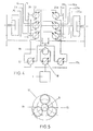
- FIG. 3 shows a diagram of a preferred embodiment, in which the translation transmission has four hydraulic motors with variable displacement.
- the translational transmission of the device of FIG. 4 includes six hydraulic motors with variable displacement and can be used for heavy vehicles requiring a high power transmission.
- FIG. 5 schematically represents a planetary gear train seen from the front, such as those used to transmit power to the wheels or the sprockets of the tracks of the vehicle.
- This planetary gear was arbitrarily represented with three planets without this number of planets having any influence on the invention.
- the powertrain comprises a power generator 1, which can be a heat engine. This drives the hydraulic translation and rotation transmissions by means of a distribution box comprising a driving road 2 and two driven pinions 3 and 3a.
- Each of the two hydraulic rotation transmissions comprises a pump (respectively 4a) delivering into a motor 5 (5a), the latter as well as the pumps 4, 4a being of variable displacement.
- the variation of this is carried out by a tachometric regulation in operation in a straight line, the turn being obtained by difference in speed of the motors 5 and 5a.
- the output shafts of the motors 5 and 5a are connected via a drive train to the central wheel 6 (6a) of each planetary output train, known per se and shown schematically as a reminder in FIG. 5.
- the translation transmission comprises a variable displacement pump 7 delivering in two variable displacement motors 8 and 8a arranged in parallel in the distribution circuit and whose output shafts 9 and 9a each carry a driving wheel 10 (10a) which transmits its power to a driven wheel 11, (11a) and by the latter to the large crown 12 (12a) of the planetary output trains.
- each planetary gear train is carried by planet carrier shafts 15, 15a which drive the non-steerable driving wheels or the sprockets of the vehicle tracks, not shown diagrammatically.
- variable displacement hydraulic elements The displacement of each of the variable displacement hydraulic elements is controlled in a known manner by tachometric regulation, which makes it possible to obtain the variations in torques and rotational speeds on the different shafts.
- the drive transmission For straight line operation of the vehicle, the drive transmission generates the torque necessary for the vehicle to move.
- the pumps 4 and 4a of the rotation transmissions also flow in the motors 5, 5a and if an equal flow and displacement are imposed, the speeds of each gypsy are equal and the vehicle is kept in a straight line while providing it additional torque and speed in its translational displacement function.
- the speed of rotation of the steering motors is varied by increasing the displacement of the rotation pump on the outside and reducing that of the pump on the inside.
- the speed of the sun gear 6a outside the turn is increased and for this, the speed of rotation of the motor 5a is increased by increasing the fluid flow rate (and therefore the displacement of the pump 4a) and / or by reducing the displacement of the motor 5a.
- the speed of the inner planetary gear train (left) is reduced.
- the fluid flow in the left rotation transmission, inside the turn, is reduced (by reducing the displacement of the pump 4 -and / or by increasing the displacement of the motor 5).
- the hydraulic components are also used for recycling within the limits of their capacity and do not need to be oversized.
- the power available on the inner road at the bend can therefore be used, the outer wheel requiring more power than that used on the inner road.
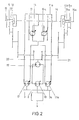
- Figure 2 shows a second embodiment in which the translation transmission comprises two hydraulic pumps 17 and 17a with variable displacement arranged in parallel in the supply circuit of two hydraulic motors with variable displacement 16 and 16a, also arranged in parallel.
- the pumps 17 and 17a whose displacement is controlled in a known manner by a tachometric regulation, are driven in rotation by the heat engine by means of the gears 3 and 3a of the distribution box.
- the motors 16 and 16a the output shafts of which are each provided with a driving wheel, drive the large crowns of the planetary output trains by means of the gears 11 and 11a.
- the steering transmission comprises a variable displacement pump 18 which delivers into a high power motor 19 with fixed displacement.
- the output shaft thereof is linked to two bevel couples 20 and 21 by means of which it drives through a complementary train of gears the planetary 6 and 6a of each epicyclic output train.
- FIG. 3 shows a preferred embodiment, in accordance with the general definition of the invention and in the second embodiment, but in which the translation transmission comprises two groups of two variable displacement motors 16, 16a and 22, 22a intended to give the vehicle torque and speed performance in translation equivalent to that given in rotation by the motor 19 with high displacement fixed displacement.
- FIG. 4 shows, according to the same embodiment, a propulsion unit for heavy vehicles whose translational transmission comprises three groups (16, 16a; 22, 22a; 23, 23a) of variable displacement engines.
- the motors 22, 22a and 23, 23a then transmit their power to the large crowns by means of gears 24, 24a and 25, 25a which are engaged on the wheels 11, 11a.
- the maximum speed is obtained in translation when the pumps 17, 17a are at maximum displacement (to obtain a maximum flow) and when the hydraulic motors 16, 16a (respectively 22 and 22a, 23 and 23a) are at the lowest displacement compatible with the conservation of a correct yield.
- the maximum torque will be reached when the capacities of the motors 17, 16a (22, 22a and 23, 23a) are maximum as well as the pressures in the supply circuit.
- the pumps 17, 17a will then have a reduced displacement so as to adapt the available torque of the heat engine to the torque absorbed by the pumps, which requires the tachometric control displacement of the pumps 17, 17a and of the engines at the speed of the heat engine.
- the turning radius of the machine will depend on the speed of the latter, all the spokes being obtainable continuously from the zero radius for turning on the spot at zero translation speed, up to the maximum radius. obtained for the maximum translation speed, the turning speed of the machine being the combination of its translation speed obtained by its translation transmission, and its rotation speed given by the steering transmission.
- the turning radius of the tank would theoretically be 13.5 m for a speed of 70 km / h with a continuous variation from a zero radius (blocking on site) at zero translation speed.
- the power available on the heat engine 1 has practically not decreased and the flow rate of the steering pump 18 is high, which results in a high speed of the hydraulic motor 19 and therefore a large speed variation on the tracks.
- the power transmission is continuous whatever the turning radius, this being directly a function of the speed of the vehicle.
- the mobility of the latter is then significantly improved.
- the invention is advantageously applicable to all tracked or wheeled vehicles requiring significant mobility and great turning power and for which the mass must be imperatively limited.
Landscapes
- Engineering & Computer Science (AREA)
- Chemical & Material Sciences (AREA)
- Combustion & Propulsion (AREA)
- Transportation (AREA)
- Mechanical Engineering (AREA)
- Non-Deflectable Wheels, Steering Of Trailers, Or Other Steering (AREA)
- Motor Power Transmission Devices (AREA)
Claims (4)
Applications Claiming Priority (2)
| Application Number | Priority Date | Filing Date | Title |
|---|---|---|---|
| FR7836290A FR2445258A1 (fr) | 1978-12-26 | 1978-12-26 | Groupe propulseur hydraulique pour vehicule, a recyclage mecanique de puissance en virage |
| FR7836290 | 1978-12-26 |
Publications (3)
| Publication Number | Publication Date |
|---|---|
| EP0013190A1 EP0013190A1 (de) | 1980-07-09 |
| EP0013190B1 true EP0013190B1 (de) | 1982-07-28 |
| EP0013190B2 EP0013190B2 (de) | 1986-09-17 |
Family
ID=9216511
Family Applications (1)
| Application Number | Title | Priority Date | Filing Date |
|---|---|---|---|
| EP19790400691 Expired EP0013190B2 (de) | 1978-12-26 | 1979-09-28 | Hydraulische Antriebsgruppe für ein Fahrzeug mit mechanischer Leistungsverzweigung beim Lenken |
Country Status (3)
| Country | Link |
|---|---|
| EP (1) | EP0013190B2 (de) |
| DE (1) | DE2963425D1 (de) |
| FR (1) | FR2445258A1 (de) |
Families Citing this family (8)
| Publication number | Priority date | Publication date | Assignee | Title |
|---|---|---|---|---|
| FR2464869A1 (fr) * | 1979-09-10 | 1981-03-20 | France Etat | Groupe propulseur a transmissions hydrostatiques assurant la translation et la direction avec recyclage hydraulique de puissance en virage |
| GB2219845A (en) * | 1988-06-14 | 1989-12-20 | Hiroshi Sato | Parallel drive hydraulic motor system |
| JP2001121983A (ja) * | 1999-10-22 | 2001-05-08 | Kanzaki Kokyukoki Mfg Co Ltd | 走行車両の操向駆動装置 |
| RU2247037C1 (ru) * | 2003-06-26 | 2005-02-27 | Южно-Уральский государственный университет | Гидрообъемная трансмиссия гусеничного трактора |
| JP4746279B2 (ja) * | 2004-03-16 | 2011-08-10 | ヤンマー株式会社 | 作業車両のトランスミッション |
| CN103963637B (zh) | 2014-04-29 | 2017-08-25 | 浙江吉利控股集团有限公司 | 一种用于车辆的整体式转向驱动桥和电动车辆 |
| CN108437786A (zh) * | 2018-03-21 | 2018-08-24 | 北京理工大学 | 一种宽传动范围液压液力机械复合式综合传动装置 |
| CN111924004B (zh) * | 2020-08-20 | 2022-02-22 | 北京理工大学 | 一种双功率流履带车辆驱动及转向系统 |
Family Cites Families (6)
| Publication number | Priority date | Publication date | Assignee | Title |
|---|---|---|---|---|
| DE957184C (de) * | 1952-08-22 | 1957-01-31 | Hydromatic G M B H | Raupenfahrzeugantrieb |
| US3426621A (en) * | 1968-02-23 | 1969-02-11 | Gen Motors Corp | Power train |
| US3575066A (en) * | 1969-09-23 | 1971-04-13 | Gen Motors Corp | Transmission |
| FR2284504A1 (fr) * | 1974-09-10 | 1976-04-09 | Zahnradfabrik Friedrichshafen | Transmission combinee de direction a superposition pour vehicules a chenilles capables de se deplacer sur la glace |
| DE2446727A1 (de) * | 1974-09-30 | 1976-04-15 | Serck Industries Ltd | Lenkungssystem fuer ein kettenfahrzeug |
| GB1559225A (en) * | 1977-02-02 | 1980-01-16 | Caterpillar Tractor Co | Hydrostatic transmission with differential steering |
-
1978
- 1978-12-26 FR FR7836290A patent/FR2445258A1/fr active Granted
-
1979
- 1979-09-28 DE DE7979400691T patent/DE2963425D1/de not_active Expired
- 1979-09-28 EP EP19790400691 patent/EP0013190B2/de not_active Expired
Also Published As
| Publication number | Publication date |
|---|---|
| EP0013190A1 (de) | 1980-07-09 |
| FR2445258B1 (de) | 1982-11-12 |
| FR2445258A1 (fr) | 1980-07-25 |
| DE2963425D1 (en) | 1982-09-16 |
| EP0013190B2 (de) | 1986-09-17 |
Similar Documents
| Publication | Publication Date | Title |
|---|---|---|
| WO2013173915A1 (fr) | Système d'entraînement des roues motrices d'un véhicule électrique ou hybride | |
| FR2538488A1 (fr) | Groupe d'entrainement pour vehicule automobile, comportant un axe principal geometrique pour l'arbre principal du moteur et un axe principal parallele pour l'arbre de sortie d'une boite de vitesses du type a trains planetaires | |
| FR2869968A1 (fr) | Transmission variable en continu du type a courroie | |
| FR2510049A1 (fr) | Systeme de propulsion par quatre roues motrices pour vehicule automobile | |
| FR2497735A1 (fr) | Systeme d'entrainement d'un vehicule | |
| EP0026115B1 (de) | Hydrostatische Getriebe mit grossem Betriebsbereich | |
| EP0013190B1 (de) | Hydraulische Antriebsgruppe für ein Fahrzeug mit mechanischer Leistungsverzweigung beim Lenken | |
| CA1142776A (fr) | Transmission hydromecanique comportant eventuellement un coupleur hydrocinetique d'appoint en particulier pour direction de vehicules chenilles | |
| FR2997047A1 (fr) | Dispositif de motorisation pour vehicule electrique | |
| FR2723777A1 (fr) | Train de transmission de puissance d'une transmission automatique pour vehicule | |
| FR2657061A1 (fr) | Dispositif de transmission a engrenages pour bicyclette. | |
| EP0493206B1 (de) | Fahrzeug mit Mischlenkung | |
| FR2689821A1 (fr) | Groupe motopropulseur bi-mode et véhicule équipé d'un tel groupe. | |
| EP0014122B1 (de) | Hydromechanische Rutsch-Lenkungsvorrichtung | |
| EP0025372B1 (de) | Antriebsgruppe mit hydrostatischer Lenkkraftübertragung für Geradeaus- und Kurvenfahrt | |
| FR2587077A1 (fr) | Appareil de changement d'entrainement en marche avant-arriere et transmission le comportant | |
| FR2475177A1 (fr) | Transmission a deux vitesses a commande hydraulique des changements de vitesse en charge | |
| FR2465130A1 (fr) | Transmission pour automobiles comportant un mecanisme a variation progressive de vitesse | |
| FR2614961A1 (fr) | Transmission dissipative a gammes multiples et rapport variable en continu | |
| EP4041581B1 (de) | Kraftübertragungsanordnung und fahrzeug mit dieser anordnung | |
| EP1008481A1 (de) | Kraftfahrzeuggetriebe | |
| EP0359654A1 (de) | Antrieb für schnelle Raupenfahrzeuge oder Fahrzeuge mit nichtgelenkten Rädern | |
| FR2464415A1 (fr) | Appareil de changement de vitesse pour tracteur | |
| FR2531173A1 (fr) | Transmission a derivation de puissance hydraulique | |
| EP0633181B1 (de) | Kraftfahrzeuglenkung durch Herbeiführen eines Geschwindigkeitsunterschiedes zwischen rechts- und linksseitigen Rädern |
Legal Events
| Date | Code | Title | Description |
|---|---|---|---|
| PUAI | Public reference made under article 153(3) epc to a published international application that has entered the european phase |
Free format text: ORIGINAL CODE: 0009012 |
|
| AK | Designated contracting states |
Designated state(s): CH DE GB SE |
|
| 17P | Request for examination filed | ||
| GRAA | (expected) grant |
Free format text: ORIGINAL CODE: 0009210 |
|
| AK | Designated contracting states |
Designated state(s): CH DE GB SE |
|
| REF | Corresponds to: |
Ref document number: 2963425 Country of ref document: DE Date of ref document: 19820916 |
|
| PLBI | Opposition filed |
Free format text: ORIGINAL CODE: 0009260 |
|
| PLBI | Opposition filed |
Free format text: ORIGINAL CODE: 0009260 |
|
| 26 | Opposition filed |
Opponent name: ZAHNRAEDERFABRIK RENK AKTIENGESELLSCHAFT Effective date: 19830421 |
|
| 26 | Opposition filed |
Opponent name: ZAHNRADFABRIK FRIEDRICHSHAFEN AKTIENGESELLSCHAFT Effective date: 19830427 |
|
| PLBG | Opposition deemed not to have been filed |
Free format text: ORIGINAL CODE: 0009274 |
|
| 26D | Opposition deemed not to have been filed |
Opponent name: ZAHNRADFABRIK FRIEDRICHSHAFEN AKTIENGESELLSCHAFT Effective date: 19830817 |
|
| PUAH | Patent maintained in amended form |
Free format text: ORIGINAL CODE: 0009272 |
|
| STAA | Information on the status of an ep patent application or granted ep patent |
Free format text: STATUS: PATENT MAINTAINED AS AMENDED |
|
| 27A | Patent maintained in amended form |
Effective date: 19860917 |
|
| AK | Designated contracting states |
Kind code of ref document: B2 Designated state(s): CH DE GB SE |
|
| PGFP | Annual fee paid to national office [announced via postgrant information from national office to epo] |
Ref country code: SE Payment date: 19910805 Year of fee payment: 13 |
|
| PGFP | Annual fee paid to national office [announced via postgrant information from national office to epo] |
Ref country code: GB Payment date: 19910917 Year of fee payment: 13 |
|
| PGFP | Annual fee paid to national office [announced via postgrant information from national office to epo] |
Ref country code: CH Payment date: 19911107 Year of fee payment: 13 |
|
| PGFP | Annual fee paid to national office [announced via postgrant information from national office to epo] |
Ref country code: DE Payment date: 19911126 Year of fee payment: 13 |
|
| PG25 | Lapsed in a contracting state [announced via postgrant information from national office to epo] |
Ref country code: GB Effective date: 19920928 |
|
| PG25 | Lapsed in a contracting state [announced via postgrant information from national office to epo] |
Ref country code: SE Effective date: 19920929 |
|
| PG25 | Lapsed in a contracting state [announced via postgrant information from national office to epo] |
Ref country code: CH Effective date: 19920930 |
|
| GBPC | Gb: european patent ceased through non-payment of renewal fee |
Effective date: 19920928 |
|
| REG | Reference to a national code |
Ref country code: CH Ref legal event code: PL |
|
| PG25 | Lapsed in a contracting state [announced via postgrant information from national office to epo] |
Ref country code: DE Effective date: 19930602 |
|
| EUG | Se: european patent has lapsed |
Ref document number: 79400691.6 Effective date: 19930406 |