EP0013265A1 - Assemblage de siège pour vannes à haute température et son utilisation dans des vannes-papillon - Google Patents
Assemblage de siège pour vannes à haute température et son utilisation dans des vannes-papillon Download PDFInfo
- Publication number
- EP0013265A1 EP0013265A1 EP79890052A EP79890052A EP0013265A1 EP 0013265 A1 EP0013265 A1 EP 0013265A1 EP 79890052 A EP79890052 A EP 79890052A EP 79890052 A EP79890052 A EP 79890052A EP 0013265 A1 EP0013265 A1 EP 0013265A1
- Authority
- EP
- European Patent Office
- Prior art keywords
- groove
- seat
- valve
- metal
- disc
- Prior art date
- Legal status (The legal status is an assumption and is not a legal conclusion. Google has not performed a legal analysis and makes no representation as to the accuracy of the status listed.)
- Granted
Links
- 238000007789 sealing Methods 0.000 claims abstract description 65
- 239000002184 metal Substances 0.000 claims abstract description 49
- 230000002093 peripheral effect Effects 0.000 claims description 13
- 239000012530 fluid Substances 0.000 claims description 10
- 125000006850 spacer group Chemical group 0.000 claims description 6
- 230000006378 damage Effects 0.000 claims description 3
- 238000003780 insertion Methods 0.000 claims description 2
- 230000037431 insertion Effects 0.000 claims description 2
- 230000003068 static effect Effects 0.000 claims description 2
- 238000011144 upstream manufacturing Methods 0.000 description 25
- 238000007373 indentation Methods 0.000 description 6
- 229920001971 elastomer Polymers 0.000 description 3
- 239000000806 elastomer Substances 0.000 description 3
- 238000012856 packing Methods 0.000 description 3
- 230000002457 bidirectional effect Effects 0.000 description 2
- 239000000463 material Substances 0.000 description 2
- -1 polytetrafluorethylene Polymers 0.000 description 2
- 229920001343 polytetrafluoroethylene Polymers 0.000 description 2
- 239000004677 Nylon Substances 0.000 description 1
- 238000000576 coating method Methods 0.000 description 1
- 230000000694 effects Effects 0.000 description 1
- 239000013536 elastomeric material Substances 0.000 description 1
- 239000007769 metal material Substances 0.000 description 1
- 229920001778 nylon Polymers 0.000 description 1
- 239000004810 polytetrafluoroethylene Substances 0.000 description 1
- 238000006748 scratching Methods 0.000 description 1
- 230000002393 scratching effect Effects 0.000 description 1
Images

Classifications
-
- F—MECHANICAL ENGINEERING; LIGHTING; HEATING; WEAPONS; BLASTING
- F16—ENGINEERING ELEMENTS AND UNITS; GENERAL MEASURES FOR PRODUCING AND MAINTAINING EFFECTIVE FUNCTIONING OF MACHINES OR INSTALLATIONS; THERMAL INSULATION IN GENERAL
- F16K—VALVES; TAPS; COCKS; ACTUATING-FLOATS; DEVICES FOR VENTING OR AERATING
- F16K1/00—Lift valves or globe valves, i.e. cut-off apparatus with closure members having at least a component of their opening and closing motion perpendicular to the closing faces
- F16K1/16—Lift valves or globe valves, i.e. cut-off apparatus with closure members having at least a component of their opening and closing motion perpendicular to the closing faces with pivoted closure-members
- F16K1/18—Lift valves or globe valves, i.e. cut-off apparatus with closure members having at least a component of their opening and closing motion perpendicular to the closing faces with pivoted closure-members with pivoted discs or flaps
- F16K1/22—Lift valves or globe valves, i.e. cut-off apparatus with closure members having at least a component of their opening and closing motion perpendicular to the closing faces with pivoted closure-members with pivoted discs or flaps with axis of rotation crossing the valve member, e.g. butterfly valves
- F16K1/226—Shaping or arrangements of the sealing
- F16K1/2263—Shaping or arrangements of the sealing the sealing being arranged on the valve seat
- F16K1/2266—Shaping or arrangements of the sealing the sealing being arranged on the valve seat and being forced into sealing contact with the valve member by a spring or a spring-like member
Definitions
- a sealing assembly for a butterfly valve is illustrated in which a soft primary seal is positioned between a pair of spaced metal secondary seals.
- the secondary metal seals are held out of contact with the seating surface of the butterfly disc by the soft seal under normal operating conditions. Only when the soft primary seal is destroyed do the secondary metal seals engage the disc in sealing relation.
- a separate resilient backing ring urges the primary soft seal and the secondary metal seals inwardly toward the seating surface of the disc.
- Copending application Serial No. 894,787 of Ronald D. Wilkins filed April 10, 1978 for "Seal Assembly for Butterfly Valve” discloses a seal assembly mounted in an annular groove about the flow passage.
- the seal assembly includes a metallic body having a pair of outer legs seated in the bottom of the groove and a pair of inner legs contacting the outer periphery of the valve disc.
- a soft seal is positioned between the inner legs and the inner ends of the inner legs contact the valve disc to provide metal sealing surfaces.
- the inner legs Upon contact with the disc, the inner legs are urged radially outwardly.
- the inner legs do not have a large radial movement and a substantial frictional force is provided by contact with the inner legs upon radially outward movement which increases the operating torque for moving the valve between open and closed positions.
- some scratching of the sealing surface on the valve disc might occur with a high frictional contact, particularly if the seal has a so-called knife edge metal contact surface.
- the seat assembly of the present invention comprises a combination metal and elastomer seat which is tight sealing, pressure and temperature responsive, and will continue to provide controlled seating in the event the soft elastomer seal is destroyed such as by fire or the like.
- a primary object of this invention is to provide a seat assembly which will accommodate a wide variation in seal contact with the valve disc while maintaining a tight seal without appreciable increases in the operating torque for the opening and closing of the valve disc.
- a further object of the invention is a valve seat design which is highly flexible and moves radially outwardly and laterally outwardly upon contact with the valve disc thereby to follow the sealing contour of the valve disc under all conditions of operation and to maintain a tight sealing contact therewith.
- the seat assembly of the present invention comprises an outer metal housing fitting within an annular groove in the body with free unrestrained inner end portions extending radially inwardly beyond the groove, the end portions having curled or arcuate ends extending in a direction generally laterally of the groove and terminating at a position laterally spaced from the groove.
- the inner end portions of the metal housing have a substantial free length which makes the inner end portions highly flexible for moving radially inwardly and radially outwardly a substantial amount thereby to follow the sealing contour of the valve disc as the disc moves into and out of a closed position under all conditions of operation.
- the curled or arcuate ends of the free end portions thus maintain a line sealing contact with the disc during and after radial deflection, both inwardly and outwardly.
- a resilient soft seal is carried by the metal housing between the end portions and engages in sealing relation the valve disc.
- the adjacent sealing surface of the butterfly valve disc is usually tapered or chamfered and fluid pressure acting against the face of the disc at the closed position thereof will move the valve disc around, for example, 0,5 mm in the downstream direction.
- the present valve is a bidirectional valve and functions with fluid flow in either direction.
- the seat assembly must be adapted to adjust for variations in tolerances and for movement of the valve disc in a downstream direction from either direction of flow.
- the highly flexible unrestrained inner end portions of the present seat assembly provide sealing contact adjacent the sealing surface of the adjacent valve disc under such conditions of operation without appreciably increasing the operating torque for moving the valve between open and closed positions. It is highly desirable to maintain a low operating torque for moving the closure member between open and closed positions and the upstream free end portion of the seat assembly must be sufficiently flexible to respond to upstream pressure and of sufficient length to follow the disc without losing sealing contact since a downstream movement of the tapered valve disc away from the upstream end portion reduces the disc diameter at seat contact.
- downstream end portion of the seat assembly must be sufficiently flexible to expand radially outwardly to accommodate a tighter engagement without causing the operating torque for moving the closure member to increase substantially.
- the upstream end portion of the seat assembly has an inner diameter smaller than the inner diameter of the downstream end portion and an unrestrained free length longer than the free length of the downstream end portion in the normal direction of fluid flow.
- Another feature of the present design is in the return of the resilient or elastomeric soft seal after the valve disc is opened by the deflected free length of the flexible upstream end portion.
- the upstream end portion returns to its undeflected free position, it forces the soft seal back to its original uncompressed position. This minimizes the effect of cold flow and creep in the soft seal which is present in many soft elastomers such as polytetrafluorethylene.
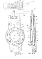
- Fig. 1 is an end elevation of the butterfly valve structure which incorporates the seat assembly comprising the present invention
- Fig. 2 is a. section taken generally along the line 2-2 of Fig. 1
- Fig. 3 is a top plan of the butterfly valve shown in Figs. 1 and 2
- Fig. 4 is an enlarged cross sectional view of the seat assembly comprising the present invention showing the seat assembly in a free unrestrained position at the open position of the closure member
- Fi g . 5 is an enlarged sectional view similar to Fig. 4 but showing the seat assembly in a deflected position with the valve closure member shown in a closed position in contact with the free inner end portions of the seat assembly
- Fig. 6 is a cross sectional view similar to Fig.
- Fig. 7 is a cross sectional view similar to Fig. 6 but showing fluid pressure applied from the right as viewed in Fig. 7
- Fig. 8 is a cross sectional view of a modified form of the invention in which a metal spacer is positioned between the sides of the metal seat structure to provide rigidity to the seat assembly upon destruction of the soft seal
- Fig. 9 is a cross sectional view of the embodiment shown in Fig. 8 with the resilient soft seal destroyed.
- the butterfly valve structure is indicated generally at 10 and comprises a body 12 having a flow passage 14 therethrough.
- a butterfly valve disc indicated generally at 16 is mounted within the flow passage for moving between open and closed positions and comprises a front face 18, a rear face 20, and an outer peripheral sealing surface 22 extending about the outer periphery of valve disc 16 and forming a generally spherical sealing surface.
- Rear face 20 has an integral sleeve 24 and a shaft 26 fitting within sleeve 24 is secured by suitable pins 28 to sleeve 24 for connecting valve disc 16 for rotation with shaft 26.
- the axial rotation of shaft 26 is offset a distance from the center line of disc 16, and may, for example, be around ca. 20 mm for a disc having a diameter of ca. 150 mm.
- Body 12 has a bore 34 receiving shaft 26.
- Packing material is illustrated at 36 and a packing retainer nut 38 engages and compresses packing material 36.
- a suitable handle 40 indicated at broken lines is secured to the upper end of shaft 26 for rotation of disc 16 between open and closed positions.
- the seat assembly comprising the present invention is illustrated generally at 42.
- Seat Assembly 42 fits in an annular groove 44 formed at joint 50 between the main body portion of body 12 and a removable annular retainer ring or plate 46.
- Screws 48 threaded into internally threaded openings in body 12 hold retainer plate 46 in tight engagement with seat assembly 42.
- Groove 44 has sides 52 and 54 which are generally parallel but have indentations or corrugations formed therein at 56.
- the bottom of groove 44 is defined by tapered surface 58 on retainer ring 46 and adjacent tapered surface 60 on the main portion of body 12.
- Seat assembly 42 fits within groove 44 and has an outer metal body or housing comprising an upstream seat ring generally indicated at 62 and a downstream seat ring generally indicated at 64 which are generally L-shaped in cross section.
- a soft resilient Lace seal is indicated at 66 positioned between upstream seat ring 62 and downstream seat ring 64.
- Upstream seat ring 52 comprises a lower leg 68 and a side 70 having corrugations or indentations 72 therein which nest within the indentations in the adjacent side 52 of groove 44.
- Upstream seat ring 62 has a free unsupported length "L" forming end portion 74 and extending to the contact line of seat ring 62 with the sealing surface 22 of valve disc 16.
- An outwardly curled or arcuate end 76 of end portion 74 engages in sealing line contact the adjacent sealing surface 22 of disc 16 at closed position.
- Downstream seat ring 64 has a lower leg 78 and a side 80 with corrugations 82 therein which nest with adjacent indentations in side 54 of groove 44. Downstream seat ring 64 has a free unsupported length indicated at "L1" forming an end portion 84 which tenninates at an outwardly curled or arcuate end 86 in metal-to-metal sealing contact with the adjacent surface 22 of disc 16.
- upstream seat ring 62 is around twice the length of the free length "L1" of downstream seat ring 64.
- pressure acting on the disc or closure member 16 tends to deflect or move the disc in a downstream direction due to tolerances and the like.
- upstream seat ring 62 should be sufficiently flexible to respond to this pressure differential and be of a sufficient lengch to follow in sealing contact the sealing surface 22 of disc 16 without losing contact with sealing surface 16.
- sealing surface 22 is generally spherical, movement in a downstream direction of disc 16 from the left viewing Figs. 4-6 reduces the diameter of disc 16 at seat contact.
- seat ring 62 should be capable of deflecting radially inwardly which reduces the inside diameter of ring 62 but yet arcuate end 76 must maintain sealing contact with surface 22.
- valve structure 10 is bidirectional and fluid pressure may act against disc 16 from either direction.
- valve disc 16 may move to the left around ca. 0,5 mm.
- the sealing contact surface 22 of disc 16 engaging arcuate end 76 increases the disc diameter at end 76 and seat ring 62 must expand radially outwardly to accommodate surface 22 and without causing the operating torque for opening and closing the valve to increase substantially.
- valve structure 10 is initially assembled, the initial deflection of upstream seat ring 62 is around twice that of downstream seat.ring 64. The amount of the initial deflection is in relation to the total free unsupported length of the respective end portions 74 and 84.
- Soft face seal 66 is preferably formed of a soft elastomeric material, such as nylon or polytetrafluoroethylene, and has a indentation in its outer face at 90 which will receive foreign matter or the like therein which adheres to the adjacent sealing surface 22 of valve disc 16.
- Soft seal 66 has indentations therein which nest with the corrugations in seat rings 62 and 64 and is tightly, gripped thereby.
- upstream seat ring 62 and downstream seat ring 64 are snapped together with soft seal 66 therebetween.
- the outer diameter of upstream seat ring 62 formed by leg 68 is slightly greater than the inner diameter of downstream seat ring 64 formed by leg 78 so a tight snap fit is provided.
- Leg 78 of seat ring 64 is flared outwardly in its free position prior to insertion within groove 44 as shown in broken lines in Fig. 4. With retainer ring 46 removed, the assembly is inserted within groove 44 and then retainer ring 46 is inserted with leg 78 contacting tapered surface 58 and being urged radially inwardly to provide a spring loaded static seal.
- groove 44 is slightly less than the width of leg 78 and when seat retainer 46 is inserted and screws 48 tightened, a metal-to-metal pressure responsive seal is formed at the corners of groove 44 indicated at 44A and 44B since leg 78 is compressed and bowed radially inwardly slightly by the sides of groove 44 to provide the seals at corners 44A and 44B which prevent any leakage through joint 50 formed by retainer ring 46 and body 12.
- upstream seat ring 62 is flexible and has a smaller diameter than the diameter of disc 16, the back surface of sealing surface 22 is contoured as shown at 22A to provide a gradual taper for contacting end 76 as the disc 16 is rotated to a fully closed position thereby to gradually urge end 76 of upstream seat ring 62 radially outwardly and laterally outwardly without pinching end 76.
- Retainer 46 has a recess at 46A receiving end 76 of upstream seat ring 62 to protect end 76 from the line flow thereby allowing seat ring 62 to relax and expand radially to its original position once disc member has been moved out of contact engagement with disc 16.
- a soft seal 66A has an annular groove 94 along its rear face 96.
- a metal spacer member indicated generally at 98 has a base 100 and an extension 102 with tapered sides or surfaces 104 and 106. Extension 102 fits within groove 84 and tapered surfaces 104 and 106 urge seal 66A outwardly to aid in retaining soft seal 66A in position between upstream seat ring 62A and downstream seat ring 64A.
- Upstream seat ring 62A and downstream seat ring 64A are identical to respective seat rings 62 and 64 of the embodiment shown in Figs. 4-7.
- Spacer members 98 supports seat rings 62A and 64A in the event of the destruction of seal 66A.
- seat ring 62A As shown in Fig. 9, with seal 66A destroyed upstream seat ring 62A is urged by very high pressure at the closed position of disc 16 against the tapered surface 106 and extension 102 thus provides a support for seat ring 62A to maintain tight metal-to-metal sealing relation with the adjacent sealing surface 22 of disc 16. Any increase in pressure results in an increased contact force from end 76A against the adjacent sealing surface 22 of disc 16.
- the seat assembly indicated generally at 42A of the embodiment shown in Figs. 8 and 9 is assembled in the same manner as the embodiment shown in Figs. 4-7 but with spacer member 98 being inserted upon the initial assembly of rings 62A and 64A.
- the metal seat rings by having a free unsupported length formed by the end portions are able to expand radially to conform to the sealing contour of the closure member or valve disc even though variations in the diameter of disc 16 may occur, and this is obtained without any appreciable increase in the operating torque for opening and closing the valve disc.
- Seat rings 62 and 64 are made of a relatively thin metal material which is preformed with arcuate ends that are radially expandable when forced into engagement with the disc. Even under repeated usage of the valve structure, the flexible end portions will contract or move radially inwardly when the valve is moved to an open position.
- a very effective sealing assembly is provided which minimizes any necessity of extremely close tolerances on the seat rings as well as the disc or closure member.
- the arcuate ends permit a line sealing contact with the adjacent closure member even though the arcuate ends may move laterally outwardly and radiallly in either direction. This also permits the deflection in the valve disc from the upstream pressure which moves the valve disc downstream.
- downstream seat ring moves radially outwardly around 0,3 mm while the upstream seat ring moves radially outwardly around 0,5 mm.
- the thickness of seat rings 62 and 64 is around 0,75 mm to maintain the desired flexibility which is necessary or inherent in a design of the type illustrated.
- the butterfly valve structure may operate under relatively high fluid pressures such as 10350 to 13800 kPa, for example.
Landscapes
- Engineering & Computer Science (AREA)
- General Engineering & Computer Science (AREA)
- Mechanical Engineering (AREA)
- Lift Valve (AREA)
- Compressor (AREA)
- Magnetically Actuated Valves (AREA)
- Valve-Gear Or Valve Arrangements (AREA)
- Catching Or Destruction (AREA)
Priority Applications (1)
| Application Number | Priority Date | Filing Date | Title |
|---|---|---|---|
| AT79890052T ATE3581T1 (de) | 1979-01-02 | 1979-11-21 | Ventilsitzanordnung fuer hochtemperaturventile und anwendung in klappenventile. |
Applications Claiming Priority (2)
| Application Number | Priority Date | Filing Date | Title |
|---|---|---|---|
| US21479A | 1979-01-02 | 1979-01-02 | |
| US214 | 1979-01-02 |
Publications (2)
| Publication Number | Publication Date |
|---|---|
| EP0013265A1 true EP0013265A1 (fr) | 1980-07-09 |
| EP0013265B1 EP0013265B1 (fr) | 1983-05-25 |
Family
ID=21690435
Family Applications (1)
| Application Number | Title | Priority Date | Filing Date |
|---|---|---|---|
| EP79890052A Expired EP0013265B1 (fr) | 1979-01-02 | 1979-11-21 | Assemblage de siège pour vannes à haute température et son utilisation dans des vannes-papillon |
Country Status (7)
| Country | Link |
|---|---|
| EP (1) | EP0013265B1 (fr) |
| JP (2) | JPS5594063A (fr) |
| AT (1) | ATE3581T1 (fr) |
| AU (1) | AU534222B2 (fr) |
| BR (1) | BR7907707A (fr) |
| CA (1) | CA1105439A (fr) |
| DE (1) | DE2965537D1 (fr) |
Cited By (3)
| Publication number | Priority date | Publication date | Assignee | Title |
|---|---|---|---|---|
| US4351511A (en) * | 1979-10-11 | 1982-09-28 | Applications Mecanique et Robinetterie Industrielle, A.M.R.I. | Sealing gasket for an obturator such as a ventilation regulator |
| EP2516901A4 (fr) * | 2009-12-21 | 2017-01-04 | Metso Flow Control Oy | Vanne et bague d'étanchéité |
| CN113280131A (zh) * | 2021-06-04 | 2021-08-20 | 重庆川仪调节阀有限公司 | 三偏心全金属蝶阀的装配方法 |
Families Citing this family (8)
| Publication number | Priority date | Publication date | Assignee | Title |
|---|---|---|---|---|
| US4341233A (en) * | 1980-06-27 | 1982-07-27 | Fmc Corporation | Fire safe seat for a rotary valve |
| US4418889A (en) * | 1981-03-16 | 1983-12-06 | Xomox Corporation | Fire safe seat for a valve |
| US4487216A (en) * | 1982-08-09 | 1984-12-11 | General Signal Corporation | Valve seal for fire safe or high temperature valves |
| GB2140896A (en) * | 1983-06-03 | 1984-12-05 | N H Engineering Limited | Ball valve seals |
| GB2206952B (en) * | 1987-07-13 | 1991-02-13 | Heat Transfer Technology | Improvements relating to valve seats |
| JP3021063B2 (ja) * | 1991-02-05 | 2000-03-15 | 株式会社エヌビーエス | バタフライバルブのシール装置 |
| US8286938B2 (en) * | 2005-12-21 | 2012-10-16 | Fisher Controls International Llc | Flexible seals for process control valves |
| WO2008149429A1 (fr) * | 2007-06-05 | 2008-12-11 | Nbs Co., Ltd. | Vanne-papillon pour très grand froid |
Citations (3)
| Publication number | Priority date | Publication date | Assignee | Title |
|---|---|---|---|---|
| DE2338353A1 (de) * | 1973-07-25 | 1975-02-20 | Borsig Gmbh | Mehrfachanpressdichtung an absperrorganen, spindeln und wellen |
| FR2279992A1 (fr) * | 1974-06-04 | 1976-02-20 | Malbranque Serseg | Dispositif d'etancheite |
| FR2408082A1 (fr) * | 1977-11-08 | 1979-06-01 | Winn Valves | Soupape tournante |
Family Cites Families (4)
| Publication number | Priority date | Publication date | Assignee | Title |
|---|---|---|---|---|
| US3986699A (en) * | 1974-07-02 | 1976-10-19 | Posi-Seal International, Inc. | Positive shut-off seal |
| JPS605823B2 (ja) * | 1975-10-24 | 1985-02-14 | マールブランク、セルセ | バタフライ弁 |
| US4113268A (en) * | 1977-03-15 | 1978-09-12 | Posi-Seal International, Inc. | Extended temperature range valve seal |
| US4162782A (en) * | 1978-04-10 | 1979-07-31 | Acf Industries, Incorporated | Seal assembly for butterfly valve |
-
1979
- 1979-10-23 AU AU52037/79A patent/AU534222B2/en not_active Ceased
- 1979-11-21 EP EP79890052A patent/EP0013265B1/fr not_active Expired
- 1979-11-21 DE DE7979890052T patent/DE2965537D1/de not_active Expired
- 1979-11-21 AT AT79890052T patent/ATE3581T1/de not_active IP Right Cessation
- 1979-11-28 BR BR7907707A patent/BR7907707A/pt unknown
- 1979-11-29 JP JP15497479A patent/JPS5594063A/ja active Pending
- 1979-12-04 CA CA341,197A patent/CA1105439A/fr not_active Expired
-
1989
- 1989-02-06 JP JP1989012289U patent/JPH01132869U/ja active Pending
Patent Citations (3)
| Publication number | Priority date | Publication date | Assignee | Title |
|---|---|---|---|---|
| DE2338353A1 (de) * | 1973-07-25 | 1975-02-20 | Borsig Gmbh | Mehrfachanpressdichtung an absperrorganen, spindeln und wellen |
| FR2279992A1 (fr) * | 1974-06-04 | 1976-02-20 | Malbranque Serseg | Dispositif d'etancheite |
| FR2408082A1 (fr) * | 1977-11-08 | 1979-06-01 | Winn Valves | Soupape tournante |
Cited By (4)
| Publication number | Priority date | Publication date | Assignee | Title |
|---|---|---|---|---|
| US4351511A (en) * | 1979-10-11 | 1982-09-28 | Applications Mecanique et Robinetterie Industrielle, A.M.R.I. | Sealing gasket for an obturator such as a ventilation regulator |
| EP2516901A4 (fr) * | 2009-12-21 | 2017-01-04 | Metso Flow Control Oy | Vanne et bague d'étanchéité |
| CN113280131A (zh) * | 2021-06-04 | 2021-08-20 | 重庆川仪调节阀有限公司 | 三偏心全金属蝶阀的装配方法 |
| CN113280131B (zh) * | 2021-06-04 | 2023-04-28 | 重庆川仪调节阀有限公司 | 三偏心全金属蝶阀的装配方法 |
Also Published As
| Publication number | Publication date |
|---|---|
| ATE3581T1 (de) | 1983-06-15 |
| CA1105439A (fr) | 1981-07-21 |
| BR7907707A (pt) | 1980-07-22 |
| EP0013265B1 (fr) | 1983-05-25 |
| JPH01132869U (fr) | 1989-09-08 |
| JPS5594063A (en) | 1980-07-17 |
| AU5203779A (en) | 1980-07-10 |
| DE2965537D1 (en) | 1983-07-07 |
| AU534222B2 (en) | 1984-01-12 |
Similar Documents
| Publication | Publication Date | Title |
|---|---|---|
| US4293116A (en) | Metallic seat assembly for valves | |
| JPS606682Y2 (ja) | 双方向性弁シ−ル装置 | |
| US4241895A (en) | Annular resilient metal valve seat | |
| US3401914A (en) | Fluid controlling valves | |
| US3894718A (en) | Ball valve | |
| KR930011371B1 (ko) | 로타리 밸브 어셈블리 | |
| US4231546A (en) | High-temperature bidirectional metal seal | |
| US4398695A (en) | Metal seal structure | |
| EP1232350B1 (fr) | Etancheite de siege de vanne a bille | |
| US4015818A (en) | Valve with self-retaining valve seat | |
| JPS645185B2 (fr) | ||
| GB2190470A (en) | Valve | |
| EP0013265B1 (fr) | Assemblage de siège pour vannes à haute température et son utilisation dans des vannes-papillon | |
| CA1166230A (fr) | Siege a l'epreuve du feu pour robinet | |
| US5118121A (en) | Compound gasket useful for high temperature, high pressure service | |
| US4487216A (en) | Valve seal for fire safe or high temperature valves | |
| US5722637A (en) | Seals | |
| GB2071281A (en) | Butterfly valve | |
| JPH04502803A (ja) | ボール弁 | |
| US4114856A (en) | Valve seat insert | |
| US5149055A (en) | Shut-off valve | |
| EP0025402B1 (fr) | Valve pour service cryogénique et garniture d'étanchéité y destinée | |
| US3447780A (en) | Plastic resin lined butterfly valve with improved sealing arrangements | |
| EP0124234B1 (fr) | Vanne | |
| JPS608380B2 (ja) | 弁封鎖装置 |
Legal Events
| Date | Code | Title | Description |
|---|---|---|---|
| PUAI | Public reference made under article 153(3) epc to a published international application that has entered the european phase |
Free format text: ORIGINAL CODE: 0009012 |
|
| AK | Designated contracting states |
Designated state(s): AT DE FR GB IT |
|
| 17P | Request for examination filed |
Effective date: 19801227 |
|
| ITF | It: translation for a ep patent filed | ||
| GRAA | (expected) grant |
Free format text: ORIGINAL CODE: 0009210 |
|
| AK | Designated contracting states |
Designated state(s): AT DE FR GB IT |
|
| REF | Corresponds to: |
Ref document number: 3581 Country of ref document: AT Date of ref document: 19830615 Kind code of ref document: T |
|
| ET | Fr: translation filed | ||
| REF | Corresponds to: |
Ref document number: 2965537 Country of ref document: DE Date of ref document: 19830707 |
|
| PLBE | No opposition filed within time limit |
Free format text: ORIGINAL CODE: 0009261 |
|
| STAA | Information on the status of an ep patent application or granted ep patent |
Free format text: STATUS: NO OPPOSITION FILED WITHIN TIME LIMIT |
|
| 26N | No opposition filed | ||
| PGFP | Annual fee paid to national office [announced via postgrant information from national office to epo] |
Ref country code: FR Payment date: 19841008 Year of fee payment: 6 |
|
| PGFP | Annual fee paid to national office [announced via postgrant information from national office to epo] |
Ref country code: DE Payment date: 19841023 Year of fee payment: 6 |
|
| PGFP | Annual fee paid to national office [announced via postgrant information from national office to epo] |
Ref country code: AT Payment date: 19861008 Year of fee payment: 8 |
|
| PG25 | Lapsed in a contracting state [announced via postgrant information from national office to epo] |
Ref country code: DE Effective date: 19890801 |
|
| PG25 | Lapsed in a contracting state [announced via postgrant information from national office to epo] |
Ref country code: GB Effective date: 19891121 Ref country code: AT Effective date: 19891121 |
|
| GBPC | Gb: european patent ceased through non-payment of renewal fee | ||
| PG25 | Lapsed in a contracting state [announced via postgrant information from national office to epo] |
Ref country code: FR Effective date: 19900731 |
|
| REG | Reference to a national code |
Ref country code: FR Ref legal event code: ST |