EP0013530A1 - Vorrichtung zum Andrücken und Falten von Kapseln an Flaschenhälsen - Google Patents
Vorrichtung zum Andrücken und Falten von Kapseln an Flaschenhälsen Download PDFInfo
- Publication number
- EP0013530A1 EP0013530A1 EP79401079A EP79401079A EP0013530A1 EP 0013530 A1 EP0013530 A1 EP 0013530A1 EP 79401079 A EP79401079 A EP 79401079A EP 79401079 A EP79401079 A EP 79401079A EP 0013530 A1 EP0013530 A1 EP 0013530A1
- Authority
- EP
- European Patent Office
- Prior art keywords
- pads
- pressing
- neck
- smoothing
- pressure chambers
- Prior art date
- Legal status (The legal status is an assumption and is not a legal conclusion. Google has not performed a legal analysis and makes no representation as to the accuracy of the status listed.)
- Granted
Links
- 238000003825 pressing Methods 0.000 title claims abstract description 37
- 210000003739 neck Anatomy 0.000 title description 35
- 230000015572 biosynthetic process Effects 0.000 claims abstract description 6
- 238000000034 method Methods 0.000 claims abstract description 4
- 238000009499 grossing Methods 0.000 claims description 31
- 239000002775 capsule Substances 0.000 claims description 21
- 239000012530 fluid Substances 0.000 claims description 16
- 150000001768 cations Chemical class 0.000 claims 1
- 235000019993 champagne Nutrition 0.000 abstract description 2
- 235000015040 sparkling wine Nutrition 0.000 abstract description 2
- 239000013013 elastic material Substances 0.000 description 4
- 239000000463 material Substances 0.000 description 2
- 230000002787 reinforcement Effects 0.000 description 2
- 230000000284 resting effect Effects 0.000 description 2
- 244000043261 Hevea brasiliensis Species 0.000 description 1
- 241001311547 Patina Species 0.000 description 1
- 230000000712 assembly Effects 0.000 description 1
- 238000000429 assembly Methods 0.000 description 1
- 230000009172 bursting Effects 0.000 description 1
- 238000005266 casting Methods 0.000 description 1
- 230000008602 contraction Effects 0.000 description 1
- 238000005553 drilling Methods 0.000 description 1
- 229920001971 elastomer Polymers 0.000 description 1
- 230000000977 initiatory effect Effects 0.000 description 1
- 238000002347 injection Methods 0.000 description 1
- 239000007924 injection Substances 0.000 description 1
- 238000004519 manufacturing process Methods 0.000 description 1
- 238000012986 modification Methods 0.000 description 1
- 230000004048 modification Effects 0.000 description 1
- 238000000465 moulding Methods 0.000 description 1
- 229920003052 natural elastomer Polymers 0.000 description 1
- 229920001194 natural rubber Polymers 0.000 description 1
- 238000005192 partition Methods 0.000 description 1
- 239000004033 plastic Substances 0.000 description 1
- 230000008016 vaporization Effects 0.000 description 1
- 238000009834 vaporization Methods 0.000 description 1
Images




Classifications
-
- B—PERFORMING OPERATIONS; TRANSPORTING
- B67—OPENING, CLOSING OR CLEANING BOTTLES, JARS OR SIMILAR CONTAINERS; LIQUID HANDLING
- B67B—APPLYING CLOSURE MEMBERS TO BOTTLES JARS, OR SIMILAR CONTAINERS; OPENING CLOSED CONTAINERS
- B67B3/00—Closing bottles, jars or similar containers by applying caps
- B67B3/02—Closing bottles, jars or similar containers by applying caps by applying flanged caps, e.g. crown caps, and securing by deformation of flanges
- B67B3/10—Capping heads for securing caps
- B67B3/16—Capping heads for securing caps characterised by having resilient deforming elements, e.g. resilient sleeves or collars
-
- B—PERFORMING OPERATIONS; TRANSPORTING
- B67—OPENING, CLOSING OR CLEANING BOTTLES, JARS OR SIMILAR CONTAINERS; LIQUID HANDLING
- B67B—APPLYING CLOSURE MEMBERS TO BOTTLES JARS, OR SIMILAR CONTAINERS; OPENING CLOSED CONTAINERS
- B67B5/00—Applying protective or decorative covers to closures; Devices for securing bottle closures with wire
- B67B5/03—Applying protective or decorative covers to closures, e.g. by forming in situ
- B67B5/032—Dies for securing overcaps
Definitions
- the present invention relates to a method and a device for folding, pressing and smoothing the folds of overcap capsules placed on the neck or the neck of a bottle, more particularly for bottles of champagne or sparkling wines, the device comprising chambers for pressurized fluids arranged in the vicinity of one another in an annular or closed configuration and being opposite from a distance, in pairs, these chambers comprising elastic extensible walls, the walls facing two facing chambers which can move towards each other by introducing a fluid under pressure into said chambers.
- the object of the present invention is to propose a device making it possible, in a single treatment station, to carry out successively the pressing with formation of folds then the folding down with smoothing of these folds, in a reliable, precise and rapid manner, for significant variations in dimensions or tolerances of the bottles or bottle caps used, as well as for a wide range of bottle neck or overcap caps shapes.
- pleat patina externally shaped to correspond to the shape of a bottle neck and on the walls dia metrically opposite pressure chambers offset angularly from the previous ones, pressing and smoothing pads for the folds are provided, also shaped to correspond to the shape of the neck of the bottle.
- the pads facing smoothing and pressing have, in cross section, a thinner thickness in the vicinity of the median zone of their surfing. pressure application only on the end-lateral parts.
- the two pleating pads facing each other present over the entire width of their pressure application surface, substantially the same thickness.
- each unit pressure application chamber juxtaposed with each other, and arranged in a rigid frame so as to have a central passage, defined by the pressing zones of the different pads, having in the direction perpendicular to a cross section, an evolving configuration to correspond substantially to the flared shape of the neck of the bottles to be capped.
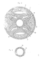
- two pleating pads 1 diametrically opposite, and orthogonal to the previous ones, two pressing and smoothing pads 2, also diametrically opposite, are formed in one piece on the internal walls respective corresponding pressure chambers 3 and 4.
- the walls 6 of the pressure chambers opposite the respective pads 1 and 2 bear on the internal face 7 of a tubular structure 8 forming a frame enclosing all of the pressure chambers.
- the elastic folding pads 1 have, over the major part of the width of their pressure application surface 9, substantially the same thickness d.
- the pressure chambers 3 associated with the pleating pads ment 1 have a cross section substantially matching the curvature of the tubular structure 8.
- the pressing and smoothing pads 2 have, in transverse section, - a thickness D which varies according to the development of their pressure application surface 10. These pads 2 have, at the level of the median zone of the application surface of pressure, reduced thickness and, in the vicinity of the lateral ends of the pressure application surface, a thickened section Dr.
- the pressure chambers 4, associated with the pads 2 have a general appearance substantially matching the curvature of the cylindrical structure of contention 8 and a substantially triangular cross-section with a corner part forming a corner 11 projecting inwards up to the level of the middle part of reduced thickness of the pads 2.
- the pads 1 and 2 are made from a flexible elastic elastic plastic material, all of these elements being made in one piece in the embodiment of the figure 1.
- the adjacent parts of the partitions delimiting the pressure chambers 3 and 4 are thus connected to each other, as well as the outer walls of the chambers bearing against the internal face 7 of the cylindrical structure forming a chassis 8.
- pressurized fluid pipes 14 which open, through openings 15, in the corresponding chambers 3 and 4 at the level of the internal faces of the pads 1 and 2, these pipes 14 being connected to supply pipes.
- pressurized fluid 16 emerging outwardly, crossing the passive zones of the walls of the pressure chambers, as shown in FIG. 2.
- the pressure supply lines 16 are mounted, in the embodiment of FIG. 2, in a cover 17 resting on the upper part of the cylindrical structure 8 and fixed to the latter, these supply pipes 16 being designed to be connected to a system for supplying pressurized fluid, for example pressurized air.
- the cores 12 and 13 serve as molding cores for the manufacture of the pressure chambers equipped with the pleating and pressing-smoothing pads, for example by casting, injection or vaporization of an elastic material, for example an elastic rubber, preferably a natural rubber.
- the support structure forming a chassis 8 has a rectangular shape with a square section, the different pressure chambers 3 and 4 being distinct and produced in the form of unitary assemblies around their internal cores.
- respective 12, 13, which here have an at least partially planar back face for their mounting in abutment against the internal faces of the frame 8 by means of locking screws 20 each received in a shoulder portion of the back face of these cores directly taking bearing on the internal face of the chassis 8, the main parts set back from these dorsal faces serving to hold by pinching, between this chassis 8, the portions of external walls of the pressure chambers.
- the mounting screws 20 can be used for the passage of the pressure fluid supply lines or, as shown in FIGS. 10 and 11, for closing plugs for the drilling hole of the pressure lines. fluid under pressure.
- the folding pads 2 have, at their median zones, a thickened convex zone 21 separating two areas of reduced thickness Dm.
- a flexible reinforcement 22 can advantageously be provided, embedded under the pressure application surface 10 of the pressing and smoothing pads 2.
- the operating mode of the device according to the present invention will now be described in relation to the phases shown in FIGS. 1, 4, 6 and 8.
- the pressure chambers are not stressed by the fluids under pressure, that is to say say with the internal walls, bearing the pads 1 and 2, bearing against the respective cores 12 and 13, the facing pressure application faces 9, respectively 10, of the pads 1 and 2 define, at the center of the device, an evolving deforming passage converging upward, corresponding substantially to the external contour of a cap or overcap capsule 19 normally affixed to a bottle already provided with a stopper. optionally held by a wire cap, as shown in Figure 2.
- the pressurized fluid is then introduced into the conjugate pair of pressure chambers 3, to bring the pleating pads 2 to pressurely press against the neck of the bottle, applying , in doing so, the capsule against the latter, the edges 30, delimiting the pressure application surface 9 of these pads 1, producing an internal fold initiation, as can be seen in FIGS. 4 and 5.
- the folding pads 1 only deform very slightly due to their relatively large thickness d.
- the pressurized fluid is then also sent to the conjugate pressure chambers 4, which causes the internal walls of these chambers to peel off from the corresponding cores 13 to bring the pads 2 in contact under pressure against the neck of the bottle, thus pressing the not yet pressed areas of the capsule 19 against the neck of the bottle and simultaneously forming the outwardly projecting folds 20 at the contact zone of the lateral parts of the pressing and smoothing pads 2 against the lateral faces of the pleating pads 1.
- the pressure is successively released in the pressure chambers 4 and 3, so that all of the pads 1 and 2 return to their rest position shown in FIG. 1, the capsule 19 on the neck of the bottle retaining the configuration shown in FIG. 7, c that is to say tightly uniformly pressed on the neck of the bottle with the exception of the narrow areas of the folds 20, which are formed with precision, on the sides of the neck.
- the pressure chambers 4 of the pressing and smoothing pads 2 are again supplied with pressurized fluid to bring the pads 2 back into pressure contact against the neck of the bottle 18.
- This overflow making the pads more enveloped pressing and smoothing 2 around the neck of the bottle, is favored, in addition by the reserve of an elastic material R, by the generally trapezoidal shape of the internal wall of the pressure chamber carrying the pressing and smoothing pad and by the central zone of reduced thickness of the latter.
- the embodiment of FIG. 11, with the additional thickness 23 or with the flexible reinforcement 22, allows application under more regular pressure of the pressing and smoothing pads 2 by restricting the amplitude of the overflow of the lateral wings of this pad around the neck of the bottle and thus limiting the risks of entrainment by sliding in rotation of the cap pressed onto the bottle neck.
- An important characteristic of the present invention resides in the fact that this overflow of the lateral wings of the pressing and smoothing pads is obtained practically without extension of the wall of the pressure chamber, by pivoting of the part of greater thickness Dr and of the reserve of elastic material R around the end portions of the central zone of reduced thickness of the pressing and smoothing pads, these deployment and contraction operations thus being carried out without creating any noticeable tension within the material of the wall, thereby guaranteeing an increased service life and reliability of the device.
- the device according to the present invention in addition to its simplicity and reliability, makes it possible to accommodate different diameters of bottle neck, for example, by admitting, for a device calculated for a nominal diameter of bottle neck of 32 mm, variations in bottle necks between approximately 25 and 40 mm in diameter, the actuation pressures being between approximately 2 and 4 bars.
- the device according to the present invention also has great security against possible bursting due to overpressure in the absence of the neck of the bottle, unlike existing devices.
Landscapes
- Engineering & Computer Science (AREA)
- Mechanical Engineering (AREA)
- Closures For Containers (AREA)
Priority Applications (1)
| Application Number | Priority Date | Filing Date | Title |
|---|---|---|---|
| AT79401079T ATE4694T1 (de) | 1979-01-13 | 1979-12-31 | Vorrichtung zum andruecken und falten von kapseln an flaschenhaelsen. |
Applications Claiming Priority (2)
| Application Number | Priority Date | Filing Date | Title |
|---|---|---|---|
| DE2901169 | 1979-01-13 | ||
| DE2901169A DE2901169C3 (de) | 1979-01-13 | 1979-01-13 | Vorrichtung zum Falten und Anpressen einer auf dem Hals einer Flasche o.dgl. sitzenden Flaschenkapsel |
Publications (2)
| Publication Number | Publication Date |
|---|---|
| EP0013530A1 true EP0013530A1 (de) | 1980-07-23 |
| EP0013530B1 EP0013530B1 (de) | 1983-09-21 |
Family
ID=6060483
Family Applications (1)
| Application Number | Title | Priority Date | Filing Date |
|---|---|---|---|
| EP79401079A Expired EP0013530B1 (de) | 1979-01-13 | 1979-12-31 | Vorrichtung zum Andrücken und Falten von Kapseln an Flaschenhälsen |
Country Status (6)
| Country | Link |
|---|---|
| US (1) | US4312168A (de) |
| EP (1) | EP0013530B1 (de) |
| AT (1) | ATE4694T1 (de) |
| CA (1) | CA1127606A (de) |
| DE (1) | DE2901169C3 (de) |
| ES (1) | ES487551A1 (de) |
Cited By (2)
| Publication number | Priority date | Publication date | Assignee | Title |
|---|---|---|---|---|
| FR2515162A1 (fr) * | 1981-10-22 | 1983-04-29 | Larrieu Bedin Girondine Ets | Dispositif de capsulage de bouteilles |
| FR2579192A1 (fr) * | 1985-03-22 | 1986-09-26 | Valet Jean Marie | Dispositif de plissement et de pressage-lissage de capsule de surbouchage |
Families Citing this family (5)
| Publication number | Priority date | Publication date | Assignee | Title |
|---|---|---|---|---|
| US6804929B2 (en) * | 2001-06-13 | 2004-10-19 | Tadeusz Kemnitz | Rotary capping apparatus and feedback control system for regulating applied torque |
| JP6916163B2 (ja) * | 2015-07-10 | 2021-08-11 | テトラ ラバル ホールディングス アンド ファイナンス エス エイ | パッケージ容器を処理するためのアセンブリ及び方法 |
| CN114620663B (zh) * | 2022-03-01 | 2023-06-23 | 山东烟郓包装科技股份有限公司 | 一种铝塑防伪瓶盖自动安装内膜的按压机 |
| EP4353671A1 (de) | 2022-10-13 | 2024-04-17 | Kematec Kellereitechnik GmbH | Flaschenverkapselvorrichtung und verfahren zum befestigen einer flaschenkapsel |
| EP4353670A1 (de) | 2022-10-13 | 2024-04-17 | Kematec Kellereitechnik GmbH | Flaschenverkapselvorrichtung und verfahren zum befestigen einer flaschenkapsel |
Citations (3)
| Publication number | Priority date | Publication date | Assignee | Title |
|---|---|---|---|---|
| FR1322257A (fr) * | 1962-02-14 | 1963-03-29 | Maison Voye Coquillard | Machine de pose de feuilles de surbouchage sur les cols de bouteille |
| FR1335059A (fr) * | 1962-07-02 | 1963-08-16 | Perfectionnements aux machines à capsuler les bouteilles de vin de champagne ou analogues | |
| FR2037383A5 (de) * | 1970-02-16 | 1970-12-31 | Jagenberg Werke Ag |
Family Cites Families (5)
| Publication number | Priority date | Publication date | Assignee | Title |
|---|---|---|---|---|
| GB191028826A (en) * | 1910-12-12 | 1912-02-12 | Frederick Whiteman | An Improved Means of Fixing Capsules to Bottle Necks, and Machinery for the Purpose. |
| US2202181A (en) * | 1939-04-17 | 1940-05-28 | George E West | Cap applying means |
| US2320515A (en) * | 1940-04-03 | 1943-06-01 | Edgar S Engle | Capping device |
| US2891366A (en) * | 1956-10-12 | 1959-06-23 | Anchor Hocking Glass Corp | Hydraulic container sealing means |
| US3039250A (en) * | 1961-05-04 | 1962-06-19 | Pancrazi Alexander | Bottle neck foiling device |
-
1979
- 1979-01-13 DE DE2901169A patent/DE2901169C3/de not_active Expired
- 1979-12-31 AT AT79401079T patent/ATE4694T1/de active
- 1979-12-31 EP EP79401079A patent/EP0013530B1/de not_active Expired
-
1980
- 1980-01-07 US US06/109,918 patent/US4312168A/en not_active Expired - Lifetime
- 1980-01-09 ES ES487551A patent/ES487551A1/es not_active Expired
- 1980-01-09 CA CA343,301A patent/CA1127606A/en not_active Expired
Patent Citations (3)
| Publication number | Priority date | Publication date | Assignee | Title |
|---|---|---|---|---|
| FR1322257A (fr) * | 1962-02-14 | 1963-03-29 | Maison Voye Coquillard | Machine de pose de feuilles de surbouchage sur les cols de bouteille |
| FR1335059A (fr) * | 1962-07-02 | 1963-08-16 | Perfectionnements aux machines à capsuler les bouteilles de vin de champagne ou analogues | |
| FR2037383A5 (de) * | 1970-02-16 | 1970-12-31 | Jagenberg Werke Ag |
Cited By (3)
| Publication number | Priority date | Publication date | Assignee | Title |
|---|---|---|---|---|
| FR2515162A1 (fr) * | 1981-10-22 | 1983-04-29 | Larrieu Bedin Girondine Ets | Dispositif de capsulage de bouteilles |
| FR2579192A1 (fr) * | 1985-03-22 | 1986-09-26 | Valet Jean Marie | Dispositif de plissement et de pressage-lissage de capsule de surbouchage |
| EP0200586A1 (de) * | 1985-03-22 | 1986-11-05 | Dekomat | Vorrichtung zum Falten, Plattdrücken und Glattstreichen von Kapseln |
Also Published As
| Publication number | Publication date |
|---|---|
| DE2901169C3 (de) | 1981-06-11 |
| ES487551A1 (es) | 1980-06-16 |
| CA1127606A (en) | 1982-07-13 |
| US4312168A (en) | 1982-01-26 |
| EP0013530B1 (de) | 1983-09-21 |
| DE2901169B2 (de) | 1980-10-02 |
| DE2901169A1 (de) | 1980-07-17 |
| ATE4694T1 (de) | 1983-10-15 |
Similar Documents
| Publication | Publication Date | Title |
|---|---|---|
| EP1007424B1 (de) | Entnahmeverschluss mit stopfen sowie verfahren zu dessen herstellung | |
| CH463985A (fr) | Dispositif de bouchage à capsule d'un flacon | |
| FR2804661A1 (fr) | Dispositif de bouchage d'un recipient et recipient pourvu d'un tel dispositif | |
| EP0330528A1 (de) | Deformierbarer rohrförmiger Behälter und Verfahren zu seiner Herstellung in einem Stück | |
| FR2473993A1 (fr) | Capsule avec joint etanche lateral | |
| WO1996001729A1 (fr) | Dispositif d'etancheite entre une ebauche de recipient en matiere plastique et une tuyere de soufflage, et machine de soufflage de recipients pourvue d'un tel dispositif | |
| EP0013530B1 (de) | Vorrichtung zum Andrücken und Falten von Kapseln an Flaschenhälsen | |
| FR2767794A1 (fr) | Ensemble de deux elements montes libres en rotation l'un par rapport a l'autre notamment pour un melangeur dans le domaine de la coloration capillaire | |
| FR2534557A3 (fr) | Dispositif d'obturation pour recipients sous pression | |
| EP0004501B1 (de) | Verschlussvorrichtung für Behälter, die einen mit einem Gewinde versehenen Hals aufweisen | |
| EP0027780A1 (de) | Flasche | |
| CH419876A (fr) | Capsule de fermeture du type serti pour bouteilles et autres récipients munis d'un col | |
| EP1284905B1 (de) | Flüssigkeitsbehälter mit scharnierverschluss | |
| FR2516899A1 (fr) | Dispositif pour prelever des substances pateuses dans des recipients remplis avec un gaz propulseur | |
| EP1149028A1 (de) | Selbstausrichtendes verschlusselement und behälter | |
| FR2752411A1 (fr) | Organe de fixation d'un dispositif de distribution sur un col d'un reservoir | |
| EP4479188B1 (de) | Spender für flüssige produkte | |
| WO2013175084A1 (fr) | Muselet de fermeture a un fil pour bouteille renfermant un liquide efferverscent et procede de fabrication associe | |
| FR2647755A1 (fr) | Emballage de type fourreau pour grouper un ensemble d'objets | |
| FR2637260A1 (fr) | Capsule de bouchage ou de surbouchage thermoretractable pour plusieurs diametres | |
| FR2777863A1 (fr) | Contenant muni d'un orifice entoure d'un col susceptible de bouchages et debouchages successifs toujours etanches et procede de fabrication de ce contenant | |
| FR3132650A1 (fr) | Distributeur de produit fluide | |
| FR2757834A1 (fr) | Dispositif d'obturation etanche d'un recipient par vissage | |
| FR2744100A1 (fr) | Bouchon destine a s'encliqueter sur le col d'un recipient | |
| CH654472A5 (fr) | Flacon equipe d'un capot de bouchage etanche. |
Legal Events
| Date | Code | Title | Description |
|---|---|---|---|
| PUAI | Public reference made under article 153(3) epc to a published international application that has entered the european phase |
Free format text: ORIGINAL CODE: 0009012 |
|
| AK | Designated contracting states |
Designated state(s): AT BE CH FR GB IT LU NL SE |
|
| 17P | Request for examination filed |
Effective date: 19810122 |
|
| ITF | It: translation for a ep patent filed | ||
| GRAA | (expected) grant |
Free format text: ORIGINAL CODE: 0009210 |
|
| RAP1 | Party data changed (applicant data changed or rights of an application transferred) |
Owner name: DEKOMAT S.A.R.L. |
|
| AK | Designated contracting states |
Designated state(s): AT BE CH FR GB IT LU NL SE |
|
| PG25 | Lapsed in a contracting state [announced via postgrant information from national office to epo] |
Ref country code: SE Effective date: 19830921 Ref country code: NL Effective date: 19830921 |
|
| REF | Corresponds to: |
Ref document number: 4694 Country of ref document: AT Date of ref document: 19831015 Kind code of ref document: T |
|
| PG25 | Lapsed in a contracting state [announced via postgrant information from national office to epo] |
Ref country code: AT Effective date: 19831001 |
|
| PG25 | Lapsed in a contracting state [announced via postgrant information from national office to epo] |
Ref country code: LU Free format text: LAPSE BECAUSE OF NON-PAYMENT OF DUE FEES Effective date: 19831231 |
|
| NLV1 | Nl: lapsed or annulled due to failure to fulfill the requirements of art. 29p and 29m of the patents act | ||
| PLBE | No opposition filed within time limit |
Free format text: ORIGINAL CODE: 0009261 |
|
| STAA | Information on the status of an ep patent application or granted ep patent |
Free format text: STATUS: NO OPPOSITION FILED WITHIN TIME LIMIT |
|
| 26N | No opposition filed | ||
| PGFP | Annual fee paid to national office [announced via postgrant information from national office to epo] |
Ref country code: CH Payment date: 19841212 Year of fee payment: 6 |
|
| PGFP | Annual fee paid to national office [announced via postgrant information from national office to epo] |
Ref country code: BE Payment date: 19841231 Year of fee payment: 6 |
|
| PG25 | Lapsed in a contracting state [announced via postgrant information from national office to epo] |
Ref country code: CH Effective date: 19861231 Ref country code: BE Effective date: 19861231 |
|
| BERE | Be: lapsed |
Owner name: DEKOMAT S.A.R.L. Effective date: 19861231 |
|
| GBPC | Gb: european patent ceased through non-payment of renewal fee | ||
| REG | Reference to a national code |
Ref country code: CH Ref legal event code: PL |
|
| PG25 | Lapsed in a contracting state [announced via postgrant information from national office to epo] |
Ref country code: GB Free format text: LAPSE BECAUSE OF NON-PAYMENT OF DUE FEES Effective date: 19881118 |
|
| ITTA | It: last paid annual fee | ||
| PGFP | Annual fee paid to national office [announced via postgrant information from national office to epo] |
Ref country code: FR Payment date: 19981229 Year of fee payment: 20 |