EP0013848A1 - Numerisch gesteuerte Drehmaschinen mit automatischer Werkstückladevorrichtung - Google Patents
Numerisch gesteuerte Drehmaschinen mit automatischer Werkstückladevorrichtung Download PDFInfo
- Publication number
- EP0013848A1 EP0013848A1 EP79400985A EP79400985A EP0013848A1 EP 0013848 A1 EP0013848 A1 EP 0013848A1 EP 79400985 A EP79400985 A EP 79400985A EP 79400985 A EP79400985 A EP 79400985A EP 0013848 A1 EP0013848 A1 EP 0013848A1
- Authority
- EP
- European Patent Office
- Prior art keywords
- carriage
- control
- machine tool
- digital control
- parts
- Prior art date
- Legal status (The legal status is an assumption and is not a legal conclusion. Google has not performed a legal analysis and makes no representation as to the accuracy of the status listed.)
- Granted
Links
- 238000006073 displacement reaction Methods 0.000 abstract description 5
- 238000007599 discharging Methods 0.000 abstract 1
- 239000004020 conductor Substances 0.000 description 8
- 238000003754 machining Methods 0.000 description 6
- 238000000151 deposition Methods 0.000 description 3
- 238000009434 installation Methods 0.000 description 3
- 238000010926 purge Methods 0.000 description 3
- 238000013022 venting Methods 0.000 description 3
- 230000000740 bleeding effect Effects 0.000 description 1
- 238000013016 damping Methods 0.000 description 1
- 230000000694 effects Effects 0.000 description 1
- 230000001960 triggered effect Effects 0.000 description 1
Images


Classifications
-
- B—PERFORMING OPERATIONS; TRANSPORTING
- B23—MACHINE TOOLS; METAL-WORKING NOT OTHERWISE PROVIDED FOR
- B23Q—DETAILS, COMPONENTS, OR ACCESSORIES FOR MACHINE TOOLS, e.g. ARRANGEMENTS FOR COPYING OR CONTROLLING; MACHINE TOOLS IN GENERAL CHARACTERISED BY THE CONSTRUCTION OF PARTICULAR DETAILS OR COMPONENTS; COMBINATIONS OR ASSOCIATIONS OF METAL-WORKING MACHINES, NOT DIRECTED TO A PARTICULAR RESULT
- B23Q7/00—Arrangements for handling work specially combined with or arranged in, or specially adapted for use in connection with, machine tools, e.g. for conveying, loading, positioning, discharging, sorting
- B23Q7/04—Arrangements for handling work specially combined with or arranged in, or specially adapted for use in connection with, machine tools, e.g. for conveying, loading, positioning, discharging, sorting by means of grippers
-
- B—PERFORMING OPERATIONS; TRANSPORTING
- B23—MACHINE TOOLS; METAL-WORKING NOT OTHERWISE PROVIDED FOR
- B23Q—DETAILS, COMPONENTS, OR ACCESSORIES FOR MACHINE TOOLS, e.g. ARRANGEMENTS FOR COPYING OR CONTROLLING; MACHINE TOOLS IN GENERAL CHARACTERISED BY THE CONSTRUCTION OF PARTICULAR DETAILS OR COMPONENTS; COMBINATIONS OR ASSOCIATIONS OF METAL-WORKING MACHINES, NOT DIRECTED TO A PARTICULAR RESULT
- B23Q1/00—Members which are comprised in the general build-up of a form of machine, particularly relatively large fixed members
- B23Q1/72—Auxiliary arrangements; Interconnections between auxiliary tables and movable machine elements
Definitions
- the invention relates to machine tools with numerical control with automatic parts loader and, more precisely, machine tools equipped with a first tool carriage whose movements are ensured by members placed under control.
- a digital control and a second carriage which carries an automatic device for loading the raw parts and unloading the machined parts which, for simplicity, will be called a loader in the following.
- the means for controlling the movements of the second loader-carrying carriage are constituted by a hydraulic cylinder whose supply and purging are ensured by means of a solenoid valve.
- a hydraulic cylinder whose supply and purging are ensured by means of a solenoid valve.
- the object of the invention is to improve machines of this kind, thanks to a simplification of the drive means of the charger-carrying carriage.
- the means for controlling the displacements of the second charger-carrying carriage consist of a releasable link capable of temporarily connecting, in a positive manner, said charger-carrying carriage to the tool-carrying carriage under the control of the existing digital control.
- this new design dispenses with the control members of the magazine carrier carriage and all the installation for controlling said members, the drawbacks of which have been mentioned above; just perform the releasable connection between the two carriages and, as in most cases, the two carriages move parallel to each other, this releasable connection can be constituted by a simple lock carried by one of the carriages and being able to engage in a strike carried by the other carriage.
- the precision of the movements of the loader carriage is very high, since it benefits from that of digital control.
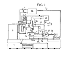
- the numerical control lathe shown in Figures 1 and 2 has a frame 1 which supports a headstock 2 and a bench 3.
- the spindle (not shown) which supports the mandrel 4 in which the parts are fixed to to machine /
- the bench 3 is provided with slides 11, 12 on which slides a first tool-carrying carriage 13 and slides 1 4, 15 parallel to the slides 11, 12 and on which slides a second magazine-carrying carriage 16.
- a transverse slide 18 On the first carriage 13 is mounted a transverse slide 18 which carries a turret 19 to horizontal axis on which the tools 21, 22, 23 are mounted, three in number in the example.
- the movements of the first carriage 13 are provided by a screw and nut 27 system 27 actuated by a motor 28 connected, by cables 31, to a digital control generally designated by 32.
- the movements of the slides 18 are provided by another screw system 34 and nut 35 actuated by a motor 36 also connected by cables 37 to said digital control 32.
- the mandrel 4 is equipped with two switches (not shown) for tightening limit switches and loosening connected respectively, by two conductors 7 and 8, to the digital control 32.
- the movements of the second loader-carrying carriage 16 are ensured from those of the first tool-carrying carriage 13, thanks to the fact that the two carriages can be coupled to one another.
- a releasable connection constituted by a lock 41 (see also Figure 3) carried by the second carriage 16 and which can engage in a keeper 42 belonging to the first carriage 13.
- the lock 41 is integral with one end of the piston rod 43 of a hydraulic cylinder 44, the cylinder 45 of which is fixed to the second carriage 16.
- the supply from a pump 46 and the bleeding of this cylinder are ensured by a solenoid valve 47 whose electrical circuit 48 is connected to the digital control 32.
- the other end of the piston rod 43 of the jack carries another lock 52 which can engage in a keeper 53 secured to the bench 3 of the turn, so that the carriage carries loader 16 can be positively immobilized in a standby position remote from the working area of the tools while a machining operation is carried out on a part mounted in the mandrel 4.
- the charger designated as a whole by 61, consists essentially of a lever 62 with two arms 62A, 62B (see also FIG. 4) pivotally mounted, by a shaft 65, on a support 66 fixed on the charger carriage 16
- the axis of the shaft 65 is a horizontal axis parallel to the axis of the lathe spindle and therefore also parallel to the slides on which the two carriages slide.
- the arm 62A carries a clamp 68 intended to grip the machined parts 5 in the mandrel 4 and to deposit them in a discharge chute 67 disposed at the front of the lathe, while the other arm 62B of the loader carries a clamp 71 intended to grab the raw parts in a waiting chute 72 and to engage them in the workpiece chuck 4.
- On the waiting chute 72 opens a magazine 73 of raw parts 5A of any suitable conventional type which will not be described in detail here.
- the two-arm lever 62 can selectively occupy three distinct angular positions, namely: an intermediate waiting position which is that shown in the drawings, a part gripping position for which its two clamps 68 and 71 are aligned, respectively, on the axis of the mandrel 4 and on the axis of the waiting chute 72, and a position for depositing parts for which its two clamps 68 and 71 are aligned this time, respectively, on the evacuation chute 67 and on the axis of the mandrel 4.
- the pivoting movements of the two-arm lever 62 of the loader are ensured by a double hydraulic cylinder 81 (FIG. 4) carried by the support 66 and in the cylinder 82 of which are mounted two differential pistons 83, 84 which are guided by a central rod 85 slidably mounted in the cylinder by its two ends and by its central part 86, of larger diameter, cut into a rack 87 engaged with a toothed pinion 88 integral with the shaft 65 of the lever with two arms 62.
- the lever is shown in its intermediate waiting position determined by the two pistons 83, 84 in internal extreme positions.
- the rod 85 carries a cleat 94 for actuating three limit switches 95, 96, 97 whose locations correspond, respectively, to the position for depositing parts, to the position for gripping parts, and to the intermediate position. waiting for the two-arm lever 62; these three switches are connected to the digital control 32 respectively by three electrical conductors 98, 99, 100- Both parts of the double jack 81 are supplied by a pump 89 and placed in the tank, respectively by two solenoid valves 91, 92 placed under the control of electrical circuits of any suitable conventional design, not shown in detail and generally designated by 93.
- the control of the opening and closing of the grippers 68, 71 of the loader, as well as the tightening and loosening command of the mandrel 4 are also carried out, in a conventional manner, by means of hydraulic jacks whose supply and purging are ensured by solenoid valves also placed under the control of the electrical circuits 93.
- These circuits include, in a conventional manner, electrical contacts of limit switches capable of causing, successively in cascade, all the necessary movements , the end of a sequence triggering the start of the next sequence.
- the magazine carrier carriage 16 occupies its standby position which is that shown in solid lines in FIG. 1, only a small distance from the machining area, so as to avoid displacements of great length which would be a cause of loss of time; it is immobilized in this position by the latch 52 ( Figure 3) engaged in the strike 53.
- the two-arm lever 62 of the loader occupies its intermediate angular position which is that shown in the drawings ( Figures 2 and 4) so as not to not interfere with the work of the tools on the workpiece.
- the digital control 32 causes the following movements: movement of the tool carriage 13 to the right until the latter is exactly opposite the carriage -loader 16 in the standby position, release of the lock 52 out of the keeper 53 and engagement of the lock 41 in the keeper 42, and displacement of the tool-carrying carriage 13 towards the headstock 2 and, consequently, also displacement of the carrying carriage -charger 16 now coupled to the tool carriage 13 by the bolt 41.
- the charger carriage 16 actuates one of the electrical contacts of the circuits 93, which causes the pivoting of the two-arm lever 62 in the opposite direction to that of the arrow f (FIGS.
- the complete loosening of the chuck causes the actuation of an electric contact corresponding electric which, via a conductor 8, informs the digital control 32; the latter then causes the carriages 13, 16 to retreat over a sufficient length so that the two parts 5A and 5 gripped respectively by the clips 71 and 68 of the loader are released from the waiting chute 72 and from the mandrel 4.
- the charger-carrying carriage 16 reaches this release position shown in solid lines in FIG. 1, it actuates an end-of-travel switch 56 connected, by a conductor 57, to the electrical control circuits 93 which cause the lever to tilt with two arms 62 in the direction of arrow f (FIGS.
- the switch 56 (FIG. 1) is actuated and informs the control circuits 93 which control the return of the two-arm lever 62 of the loader to the intermediate waiting position shown in the drawings by the pressurization of the extreme chambers 82C , 82D of the jack 81 (FIG. 4) by means of the solenoid valve 92.
- the cleat 94 actuates the switch 97 which, via the conductor 100, informs the control digital; this causes the return of the tool carriage 13 alone to its working position and the start of a new cycle machining on the part 5A in place in the mandrel 4.
- the two limit switches 54, 56 could be replaced by information entered in the digital control 32.
Landscapes
- Engineering & Computer Science (AREA)
- Mechanical Engineering (AREA)
- Feeding Of Workpieces (AREA)
- Turning (AREA)
Applications Claiming Priority (2)
| Application Number | Priority Date | Filing Date | Title |
|---|---|---|---|
| FR7900398A FR2446152A1 (fr) | 1979-01-09 | 1979-01-09 | Machine-outil a commande numerique avec chargeur automatique de pieces |
| FR7900398 | 1979-01-09 |
Publications (3)
| Publication Number | Publication Date |
|---|---|
| EP0013848A1 true EP0013848A1 (de) | 1980-08-06 |
| EP0013848B1 EP0013848B1 (de) | 1982-10-27 |
| EP0013848B2 EP0013848B2 (de) | 1986-07-02 |
Family
ID=9220551
Family Applications (1)
| Application Number | Title | Priority Date | Filing Date |
|---|---|---|---|
| EP19790400985 Expired EP0013848B2 (de) | 1979-01-09 | 1979-12-07 | Numerisch gesteuerte Drehmaschinen mit automatischer Werkstückladevorrichtung |
Country Status (3)
| Country | Link |
|---|---|
| EP (1) | EP0013848B2 (de) |
| DE (1) | DE2963959D1 (de) |
| FR (1) | FR2446152A1 (de) |
Cited By (3)
| Publication number | Priority date | Publication date | Assignee | Title |
|---|---|---|---|---|
| EP0059013A1 (de) * | 1981-02-12 | 1982-09-01 | N.V. Gereedschapswerktuigenindustrie Hembrug | Reitstock für eine Werkzeugmaschine |
| CN104942316A (zh) * | 2015-07-01 | 2015-09-30 | 芜湖扬宇机电技术开发有限公司 | 一种卧式车床紧急停车附加系统及其控制方法 |
| CN114211014A (zh) * | 2022-01-08 | 2022-03-22 | 河南国泰达鸣精密机件有限公司 | 自动车床凸轮与气动复合送料机构 |
Citations (4)
| Publication number | Priority date | Publication date | Assignee | Title |
|---|---|---|---|---|
| BE561921A (de) * | ||||
| US3575302A (en) * | 1968-09-25 | 1971-04-20 | Sfm Corp | Work handling mechanism |
| DE2249441A1 (de) * | 1972-10-09 | 1974-04-18 | Ims Joh Morat Und Soehne Gmbh | Hydraulisch arbeitende be- und entladeeinrichtung fuer fertigungsmaschinen, insbesondere waelzfraesmaschinen |
| DE2614003B1 (de) * | 1976-04-01 | 1977-09-01 | Hegenscheidt Gmbh Wilhelm | Senkrechtdrehmaschine |
-
1979
- 1979-01-09 FR FR7900398A patent/FR2446152A1/fr active Granted
- 1979-12-07 EP EP19790400985 patent/EP0013848B2/de not_active Expired
- 1979-12-07 DE DE7979400985T patent/DE2963959D1/de not_active Expired
Patent Citations (4)
| Publication number | Priority date | Publication date | Assignee | Title |
|---|---|---|---|---|
| BE561921A (de) * | ||||
| US3575302A (en) * | 1968-09-25 | 1971-04-20 | Sfm Corp | Work handling mechanism |
| DE2249441A1 (de) * | 1972-10-09 | 1974-04-18 | Ims Joh Morat Und Soehne Gmbh | Hydraulisch arbeitende be- und entladeeinrichtung fuer fertigungsmaschinen, insbesondere waelzfraesmaschinen |
| DE2614003B1 (de) * | 1976-04-01 | 1977-09-01 | Hegenscheidt Gmbh Wilhelm | Senkrechtdrehmaschine |
Cited By (3)
| Publication number | Priority date | Publication date | Assignee | Title |
|---|---|---|---|---|
| EP0059013A1 (de) * | 1981-02-12 | 1982-09-01 | N.V. Gereedschapswerktuigenindustrie Hembrug | Reitstock für eine Werkzeugmaschine |
| CN104942316A (zh) * | 2015-07-01 | 2015-09-30 | 芜湖扬宇机电技术开发有限公司 | 一种卧式车床紧急停车附加系统及其控制方法 |
| CN114211014A (zh) * | 2022-01-08 | 2022-03-22 | 河南国泰达鸣精密机件有限公司 | 自动车床凸轮与气动复合送料机构 |
Also Published As
| Publication number | Publication date |
|---|---|
| DE2963959D1 (en) | 1982-12-02 |
| EP0013848B1 (de) | 1982-10-27 |
| FR2446152B1 (de) | 1981-02-27 |
| EP0013848B2 (de) | 1986-07-02 |
| FR2446152A1 (fr) | 1980-08-08 |
Similar Documents
| Publication | Publication Date | Title |
|---|---|---|
| CH502866A (fr) | Machine-outil à changement automatique d'outils | |
| EP0035952B1 (de) | Automatische Werkzeugwechselvorrichtung, anwendbar bei Werkzeugmaschinen mit vertikaler oder horizontaler Spindel, und automatische Mittel zum Erfassen und Ausrichten dieser Werkzeuge in den Spindeln der Werkzeugmaschinen | |
| CH646892A5 (fr) | Procede de decoupage par decharges electriques. | |
| FR2526343A1 (fr) | Tour automatique revolver multibroche | |
| FR2677287A1 (fr) | Appareil de changement d'outils pour une poinconneuse a tourelle. | |
| FR2732633A1 (fr) | Procede et dispositif de changement d'outil pour un centre d'usinage | |
| FR2593731A1 (fr) | Machine et procede pour le montage d'un soufflet | |
| FR2556627A1 (fr) | Perceuse | |
| EP0013848B1 (de) | Numerisch gesteuerte Drehmaschinen mit automatischer Werkstückladevorrichtung | |
| EP0033689B1 (de) | Automatische Transfervorrichtung für Gegenstände | |
| FR2615138A1 (fr) | Dispositif de changement d'outil pour machine-outil, notamment pour perceuse ou taraudeuse | |
| EP0343195A1 (de) | Maschine zur mechanischen bearbeitung von werkstücken | |
| FR2467052A1 (fr) | Dispositif de poste d'outils pour machine-outil | |
| FR2490974A1 (fr) | Ensemble pour la fabrication de pieces par moulage sous pression ou par injection | |
| FR2465557A1 (fr) | Changeur automatique d'outils pour machines-outils en general permettant le transfert de chaque outil depuis la broche porte-outils jusqu'a un magasin d'outils tournant | |
| EP0936027A1 (de) | Bearbeitungsvorrichtung zum stirnseitigen Bearbeiten in einer Werkzeugmaschine | |
| FR2488679A1 (en) | Circular grinding machine workpiece clamping and forwarding device - has retractable blocking bolt and indexing bolts incorporated in facing clamps | |
| CH403442A (fr) | Dispositif de ravitaillement pour tour automatique à poupée mobile | |
| FR2564352A1 (fr) | Dispositif de transfert et de stockage d'outils pour fraiseuses, centres d'usinage et machines analogues | |
| FR2511283A1 (fr) | Dispositif de changement automatique d'outil pour machine-outil | |
| EP0052023A1 (de) | Numerisch gesteuerte Werkzeugmaschine mit Werkzeugmagazin | |
| FR2581338A1 (fr) | Dispositif de changement d'outils pour bras automatique | |
| CH504265A (fr) | Machine-outil à changement automatique d'outils | |
| FR2527494A3 (fr) | Dispositif de changement d'outil pour centres de travail avec magasin d'outillage de grande capacite | |
| FR2615137A1 (fr) | Unite trois axes a commande numerique, notamment pour machine transfert et atelier flexible |
Legal Events
| Date | Code | Title | Description |
|---|---|---|---|
| PUAI | Public reference made under article 153(3) epc to a published international application that has entered the european phase |
Free format text: ORIGINAL CODE: 0009012 |
|
| AK | Designated contracting states |
Designated state(s): BE CH DE GB IT |
|
| 17P | Request for examination filed |
Effective date: 19801017 |
|
| ITF | It: translation for a ep patent filed | ||
| GRAA | (expected) grant |
Free format text: ORIGINAL CODE: 0009210 |
|
| AK | Designated contracting states |
Designated state(s): BE CH DE GB IT |
|
| REF | Corresponds to: |
Ref document number: 2963959 Country of ref document: DE Date of ref document: 19821202 |
|
| PLBI | Opposition filed |
Free format text: ORIGINAL CODE: 0009260 |
|
| PLBI | Opposition filed |
Free format text: ORIGINAL CODE: 0009260 |
|
| 26 | Opposition filed |
Opponent name: GILDEMEISTER AG Effective date: 19830715 |
|
| 26 | Opposition filed |
Opponent name: INDEX-WERKE KG HAHN & TESSKY Effective date: 19830723 |
|
| PGFP | Annual fee paid to national office [announced via postgrant information from national office to epo] |
Ref country code: BE Payment date: 19831130 Year of fee payment: 5 |
|
| PGFP | Annual fee paid to national office [announced via postgrant information from national office to epo] |
Ref country code: CH Payment date: 19840125 Year of fee payment: 5 |
|
| PGFP | Annual fee paid to national office [announced via postgrant information from national office to epo] |
Ref country code: DE Payment date: 19850225 Year of fee payment: 6 |
|
| PUAH | Patent maintained in amended form |
Free format text: ORIGINAL CODE: 0009272 |
|
| STAA | Information on the status of an ep patent application or granted ep patent |
Free format text: STATUS: PATENT MAINTAINED AS AMENDED |
|
| 27A | Patent maintained in amended form |
Effective date: 19860702 |
|
| AK | Designated contracting states |
Kind code of ref document: B2 Designated state(s): BE CH DE GB IT |
|
| ITF | It: translation for a ep patent filed | ||
| PG25 | Lapsed in a contracting state [announced via postgrant information from national office to epo] |
Ref country code: CH Effective date: 19871231 Ref country code: BE Effective date: 19871231 |
|
| BERE | Be: lapsed |
Owner name: H. ERNAULT-SOMUA Effective date: 19871231 |
|
| GBPC | Gb: european patent ceased through non-payment of renewal fee | ||
| REG | Reference to a national code |
Ref country code: CH Ref legal event code: PL |
|
| PG25 | Lapsed in a contracting state [announced via postgrant information from national office to epo] |
Ref country code: DE Effective date: 19880901 |
|
| PG25 | Lapsed in a contracting state [announced via postgrant information from national office to epo] |
Ref country code: GB Free format text: LAPSE BECAUSE OF NON-PAYMENT OF DUE FEES Effective date: 19881118 |
|
| PLAB | Opposition data, opponent's data or that of the opponent's representative modified |
Free format text: ORIGINAL CODE: 0009299OPPO |