EP0013984A1 - Procédé et appareil pour le déroulement d'une bande sans fin à partir d'une réserve de bande - Google Patents
Procédé et appareil pour le déroulement d'une bande sans fin à partir d'une réserve de bande Download PDFInfo
- Publication number
- EP0013984A1 EP0013984A1 EP80100357A EP80100357A EP0013984A1 EP 0013984 A1 EP0013984 A1 EP 0013984A1 EP 80100357 A EP80100357 A EP 80100357A EP 80100357 A EP80100357 A EP 80100357A EP 0013984 A1 EP0013984 A1 EP 0013984A1
- Authority
- EP
- European Patent Office
- Prior art keywords
- winding
- tape
- speed
- washer
- windings
- Prior art date
- Legal status (The legal status is an assumption and is not a legal conclusion. Google has not performed a legal analysis and makes no representation as to the accuracy of the status listed.)
- Granted
Links
- 238000000034 method Methods 0.000 title claims abstract description 31
- 230000008569 process Effects 0.000 title description 7
- 238000004804 winding Methods 0.000 claims abstract description 172
- 230000008878 coupling Effects 0.000 claims description 23
- 238000010168 coupling process Methods 0.000 claims description 23
- 238000005859 coupling reaction Methods 0.000 claims description 23
- 230000001105 regulatory effect Effects 0.000 claims description 13
- 230000001276 controlling effect Effects 0.000 claims description 6
- 230000001419 dependent effect Effects 0.000 claims description 4
- 238000012216 screening Methods 0.000 claims description 3
- 230000000694 effects Effects 0.000 claims description 2
- 230000005484 gravity Effects 0.000 claims description 2
- 238000012546 transfer Methods 0.000 claims description 2
- 238000013461 design Methods 0.000 description 7
- 230000007423 decrease Effects 0.000 description 5
- 239000000463 material Substances 0.000 description 4
- 230000009471 action Effects 0.000 description 2
- 230000008901 benefit Effects 0.000 description 2
- 239000003292 glue Substances 0.000 description 2
- 230000001360 synchronised effect Effects 0.000 description 2
- 230000001154 acute effect Effects 0.000 description 1
- 230000015572 biosynthetic process Effects 0.000 description 1
- 230000003247 decreasing effect Effects 0.000 description 1
- 230000000994 depressogenic effect Effects 0.000 description 1
- 238000011161 development Methods 0.000 description 1
- 238000006073 displacement reaction Methods 0.000 description 1
- 230000003670 easy-to-clean Effects 0.000 description 1
- 238000004519 manufacturing process Methods 0.000 description 1
- 238000013508 migration Methods 0.000 description 1
- 230000005012 migration Effects 0.000 description 1
- 230000002093 peripheral effect Effects 0.000 description 1
- 239000007787 solid Substances 0.000 description 1
- 238000012549 training Methods 0.000 description 1
- 230000007704 transition Effects 0.000 description 1
Images


Classifications
-
- G—PHYSICS
- G03—PHOTOGRAPHY; CINEMATOGRAPHY; ANALOGOUS TECHNIQUES USING WAVES OTHER THAN OPTICAL WAVES; ELECTROGRAPHY; HOLOGRAPHY
- G03B—APPARATUS OR ARRANGEMENTS FOR TAKING PHOTOGRAPHS OR FOR PROJECTING OR VIEWING THEM; APPARATUS OR ARRANGEMENTS EMPLOYING ANALOGOUS TECHNIQUES USING WAVES OTHER THAN OPTICAL WAVES; ACCESSORIES THEREFOR
- G03B21/00—Projectors or projection-type viewers; Accessories therefor
- G03B21/14—Details
- G03B21/32—Details specially adapted for motion-picture projection
Definitions
- the invention relates to a method for circulating (passing through) an endless band in a supply, which is provided in the form of two concentric windings, each essentially having a vertical axis of rotation, the outer winding of the outer winding being carried out via an external, loop-like length section of the tape is connected to the inner turn of the inner roll and the inner turn of the outer roll directly via an internal length section of the tape to the outer turn of the inner roll and wherein all turns of the outer roll are min at least one element and all windings of the inner winding are carried by at least one other element and driven in their circumferential direction and this drive with the outer winding of the outer winding and with the inner winding of the inner winding in each case with the same running speed of the external belt. Length section corresponding speed takes place.
- the invention further relates to an apparatus for performing the method for circulating (passing through) an endless belt, e.g. of a film tape to be presented in a demonstration device, in a supply which is provided in the form of two concentric coils, each essentially having a vertical axis of rotation, the outer turn of the outer roll being carried out via an external, loop-like length section of the tape with the inner turn of the inner winding and the inner winding of the outer winding is connected directly to the outer winding of the inner winding via an internal length section of the band, with a carrying device which consists of at least two elements carrying and driving each winding, with one of which the band consists of leading out inner winding of the inner winding, on a stationary core arranged centrally in the carrying device and with a device controlling the drive of the outer winding of the outer winding and a drive of the inner winding of the inner winding.
- an endless belt e.g. of a film tape to be presented in a demonstration device
- a supply which is provided in
- Such a method mentioned at the outset is used in a known device, the supply of the endless belt being provided in the form of two concentric windings which merge directly into one another.
- the winding can be viewed as a spatial unit, but functionally it can be divided into an outer and an inner winding.
- the inner and outer windings rotate at different speeds, each of which is dependent on the strip being fed in or out.
- the film tape to be guided for example for a projection by a demonstration device, is led out of the tape supply placed on it by the inner turn of the inner roll and, after passing through the show device, is fed onto the outer turn of the outer roll.
- the tape supply is taken up by a carrying device, which consists of a stationary core arranged around a vertical axis, around which elements carrying and driving the winding are arranged in a circle.
- These elements consist of cylindrical rollers which are arranged with their longitudinal axes radially to the vertical axis of the core and at a fixed distance from one another.
- These eight rollers are divided into two independently drivable groups of four rollers, which are arranged alternately. Four rollers of one group are inclined with their longitudinal axes inwards with respect to the horizontal, so that the common surface formed from the upward surface lines of the four rollers arranged in a circle forms a very flat funnel with the opening pointing upwards.
- the four other rollers of the second group have an inclination opposite to that of the first group, so that the common surface formed from their upper surface lines forms a cone with the tip pointing upwards.
- the inwardly inclined rollers support the outer part of the tape roll, the outwardly inclined rollers the inner part of the tape roll.
- the ends of the rolls near the stationary core are connected to drive wheels which rest on two concentrically arranged drive plates which are arranged in different horizontal planes according to the inclination differences of the rolls of the two groups. Both roller groups can be driven at different speeds by the independent drive actuators.
- the stationary core also consists of eight guide rollers, which are arranged in the spaces between the eight rollers and can be rotated about vertical axes, against which the inner winding of the inner winding lies and at the same time forms the smallest diameter of the tape winding supply.
- the tape end to be fed to the projection device is guided out of the device out of the inner handling of the tape roll around one of the guide rollers and inwards and obliquely upwards over the entire tape roll.
- the end coming from the projection device is simply wound onto the outer turn of the tape roll.
- the arrangement of the two roller groups driven at different speeds means that only the precise rotational speed of two turns of the wound tape reel can be set.
- the object of the invention is to provide both a method and a device for circulating (passing through) an endless belt in a supply in such a way that any friction between the adjacent belts or windings is avoided and the entire winding process can be carried out reliably that in particular there are no excessive tensile stresses in the strip material, the method should be suitable for different amounts of film and the device can also be constructed in a structurally simple manner.
- An advantage of this method according to the invention is that, because of the radial spacing, the two windings can freely rotate, independently of one another, the two windings can be driven at different speeds, without different longitudinal displacements between the tape turns must occur and thus inevitably occurs a band friction.
- the external, loop-shaped length section of the endless belt which is led out of the supply is removed from the inner turn of the inner roll and, after passing through, e.g. a projection device again as the outer turn of the outer winding.
- a projection device again as the outer turn of the outer winding.
- the supply of endless belt is provided in the form of more than two windings located essentially in the same horizontal plane, and the angular velocities of the windings located between the outer and the inner windings are smaller or temporarily equal to the angle speed of the inner roll and temporarily equal to or greater than the angular speed of the outer roll.
- This additional arrangement of a plurality of windings between the inner and outer windings makes it possible to subdivide the tape winding supply which has been placed on it, in accordance with its composition. This can be particularly advantageous if the tape supply is the entire film program to be played through within a time unit and is composed, for example, of several individual films or consists of a film with different files.
- the winding speed of its outer turn is now adapted to the running speed of the supplied external length section of the tape and a new inner roll is formed, the winding speed of which corresponds to the inner turn , which is also dependent on the running speed of the removed external length section of the band and the new outer and the new inner winding are connected to an inner length section of the band bridging the radial distance.
- the object of the invention is further achieved by a device of the type mentioned above in that the support device consists of at least three concentric annular disks rotatable about the stationary core, the outer annular disk being drivable with and depending on the device controlling the winding speed and rotating speed the inner ring disk can be driven at a speed which is also variable as a function of the device controlling the unwinding speed, and the intermediate ring disk can be driven at a speed corresponding to either the outer ring disk or the inner ring disk.
- the design of the elements forming the carrying device and driving the windings as concentric annular disks results in a structurally simple carrying device which uniformly accommodates the strip material.
- the arrangement of the ring disks is done in a very simple manner concentrically around the stationary core located in the center of the device and forms with it an essentially flat surface, which e.g. is easy to clean and maintain. All drive units and control devices are arranged and protected either on the stationary core or below the ring disks or below the stationary core.
- annular disks located between the outer and inner annular disk are advantageously arranged. These further intermediate ring disks make it possible to place and circulate a much larger band supply on the device.
- the surface of all the ring disks advantageously lies approximately in the same plane of rotation, the axis of which lies in the axis of rotation of the ring disks. It is also advantageous that the intermediate ring disks have the same surfaces. As a result of this and due to design requirements, in particular due to the drive located underneath the intermediate ring and the arrangement of an annular groove in which drive or support wheels can run, it is necessary that the width of the outer intermediate annular disc is not less than 1 can be up to 2 centimeters.
- the inner washer has at least the same area as the intermediate washers.
- the inner ring disk preferably has an area 1.5 to 4.0 times larger than the intermediate ring disk.
- the outer annular disk has at least the same area as the intermediate annular disk, but preferably an area which is twice as large. This configuration means that the film material to be wound onto the outer ring disk does not exceed the outer diameter of the outer ring disk and can therefore fall off the carrying device.
- the area of the inner ring disk is smaller than the area of the smallest tape roll to be used in operation.
- the area of the inner ring disk is preferably 1/3 of the tape winding used in operation.
- the sum of the areas of the intermediate ring disks is at least the same, preferably larger than the area of the largest tape reel to be played.
- the outer annular disc and the inner annular disc are each driven by a variable in its speed motor, where '' ei is the speed by controlling a function of the integrated supplied in the SET TIME or discharged length of ribbon A direction is regulated.
- coupling elements are arranged in each case, which are designed in such a way that, based on the usual direction of travel of the device, they permit a higher rotational speed of the inner washer in each case and, on the other hand, ensure driving with at least the rotational speed of the outer washer is.
- the coupling elements on the outer edge of the intermediate ring disks are preferably single-arm levers which can be rotated about a horizontal axis lying in the radial direction and arranged within a groove tangential to the edge of the ring disks, and as a radial axis on the inner edge of the intermediate ring disks and the outer ring disk horizontally arranged drivers formed, which rests against the one-arm levers which hang down under their gravity.
- switchable clutches are arranged, which are switchable depending on the diameter of the inner winding and the intermediate ring disks according to the speed of the inner winding of the inner winding take.
- These couplings are designed as lever-shaped rockers, which are pressed down by the load due to the application of windings of a tape winding and bear against the drivers arranged on the inner edges of the intermediate annular discs and the outer annular disc.
- the intermediate annular disks can each advantageously have their own motor-driven drive that can be controlled with variable speed.
- These drives are designed as stepper motors which, depending on the assignment of the intermediate ring disks, are connected together in turns.
- the arrangement of coupling elements between the individual ring disks is omitted, and the rotational speeds of the individual ring disks are adjusted electrically.
- control device regulating the unwinding speed of the inner tape reel is advantageously attached to the core.
- This control device responds to the position and / or shape of the tape section extending between the inner handling of the tape reel and the control device in the form of a loose loop and influences the speed of the inner ring disk depending on its position or shape changes.
- the control device regulating the winding speed of the outer tape reel is designed in the form of a lever arm which is articulated underneath the ring disks and can be swiveled horizontally about a vertical axis and which carries a deflection roller which can be rotated about a vertical axis at its end which projects beyond the outer edge of the outer ring disk and around which the tape to be wound into shape a supply loop between the projector and the outer winding is guided.
- the stationary core has on its outer circumference adjacent to the inner edge of the inner ring disk, at a distance from each other, rotatably mounted about vertical axes. When a new inner winding is formed, its inner winding bears against these rollers and can rotate smoothly around the stationary core at the speed specified by the inner ring disc.
- the concentrically arranged annular disks can advantageously lie against one another with their horizontal surfaces in a step-like manner, and the next annular disk following from inside to outside increases by an amount of a few millimeters.
- the annular disc which is arranged next to the outside in each case, overlaps with its fold-like inner edge on the outer edge of the adjacent adjacent annular disc, which is a few millimeters lower. This preferred embodiment of the device prevents gaps which are open at the top between the individual ring disks and which could hinder the transport of the band windings between the ring disks from the outer to the inner winding.
- the concentrically arranged annular disks can also have an inwardly inclined surface and, in their entirety, have the shape of a very flat funnel.
- a deflection device which is connected downstream of the control device regulating the winding speed of the tape reel and which guides the tape to be fed to the projector out of the inner reel and over the ring disks.
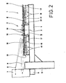
- FIGS. 1 and 2 of the device for carrying out the method for circulating (passing through) an endless band for example a film band to be shown in a demonstration device, essentially comprises a carrying device 1 on which the band roll is provided in a supply and a removal device 2, which leads the tape out of the inner handling of the tape roll provided.
- the carrying device 1 consists of nine concentrically arranged circular ring disks, which are arranged around a common vertical central axis 3. According to their function, which will be described later in the description of the method, these ring disks are subdivided into an outer ring disk A, seven intermediate ring disks B 1 - B 7 and an inner ring disk C. These ring disks rotate counterclockwise around a centrally arranged one stationary core D, which carries the removal device 2 and is fastened on a cross-shaped holder 4 held by a post 5.
- the projector 7 is also attached to a bracket 6 of the post 5.
- the height of the projector 7 and the carrying device 1 or holder 4 are matched to one another in accordance with the band guides 8 and 9. Relative to the tracing device 2, the tape emitted by the projector 7 is fed via tape guide 9 and the tape to be fed to the projector is removed via tape guide 8.
- Bracket 4, post 5 and console 6 are made from known I-beams or from hollow profiles.
- the intermediate ring disks B 1 - B 7 all have the same circular ring area, as a result of which the width of each intermediate ring decreases with increasing diameter.
- the inner washer C has an area 4 times larger than that of the intermediate washers.
- the outer washer A has twice the area of an intermediate washer. This prevents the last windings from possibly falling off the outer washer when winding up the band guided over the band guide 9, although it is computationally sufficient if the area of the outer washer corresponds to the area of an intermediate washer.
- all subsequent ring disks are each arranged to increase in height by an amount of a few millimeters.
- the inner edges of the intermediate washers B 1 - B 7 and the outer washer A have a rabbet-like design, so that the outwardly following washer covers the space between it and the inner washer and the edge thereof (see FIGS. 3 and Fig 6). This configuration prevents a single band winding from falling through or being trapped between the ring disks.
- All ring disks are mounted on disk wheels 10, which have different diameters according to their assignment to the individual ring disks and are arranged at an appropriate distance on an axis 11.
- the axles 11 common to the disc wheels are each attached to the four arms of the cross-shaped holder 4 by means of bearings 12. (See Fig. 2).
- the washers have an annular groove 13 on their underside, while the inner washer C is provided with two annular grooves because of its greater width.
- These ring grooves serve as raceways for the disk wheels 10 and, in addition to the storage of the ring disks on the disk wheels 10, also simultaneously perform the precise concentric guidance of the individual ring disks.
- the inner ring disk C and the outer ring disk A are driven directly by separately arranged motors.
- the drive motors are not in the drawings shown.
- the outer washer A can be driven by an electric motor mounted on the bracket 4 near the post 5 via a friction wheel on its outer edge.
- the inner washer can also. C are driven by a friction wheel on their underside.
- both drives are controlled depending on the wound or removed tape.
- two separate devices are provided which control the rotational speeds of the corresponding ring disks.
- the speed of rotation of the outer ring disk A is regulated as a function of the winding speed of the tape fed from the tape guide 9 by the projector 7 via a control device 14.
- This control device 14 has a deflection roller 16 arranged on a vertical axis 15, around which the band to be wound is guided.
- the axis 15 is fastened to a lever arm 17 which is pivotably mounted at a suitable point on the holder 4 or on the stationary core D and is connected to an electrical control device which controls the speed of the drive motor of the outer annular disc A.
- the deflection roller 16 can yield under spring action and influence the regulating device via the lever arm 17 in such a way that the winding speed is reduced or accelerated via the outer annular disc A.
- a control device 18 regulating the speed of rotation of the inner ring disk C is located on the stationary core D in connection with the removal device 2 for guiding the tape out of the inner handling of the tape roll.
- This device is the subject of patent 19 52 592 by the same applicant and will not be described in more detail here.
- Both control devices have in common that they actuate a regulating device which influences the speed of the corresponding ring disks and which essentially consist of an actuator and a rotary transformer which can be adjusted by the latter.
- the servomotor rotates in the sense of an increase or decrease in the voltage tapped at the rotary transformer and thus brings about a corresponding increase or decrease in the speed of the drive motor for the annular disks fed by the rotary transformer.
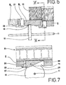
- FIGS. 3, 4 and 5 illustrate the system of the upper couplings 20.
- the partial section through the intermediate annular disks B 1 , B 2 and B 3 is shown in FIG. 3 .
- the intermediate ring disks B 1 and B 3 are each covered with parts of the two coils 21 and 22.
- the inner tape roll 21 rotates together with the intermediate ring disk B 1 in accordance with the rotational speed of the inner ring disk C, which rotates depending on the unwinding speed of the inner turn of the tape roll 21.
- the outer tape winding 22 rotates together with the intermediate annular disk B 3 and the remaining intermediate annular disks B 4 - B 7 at the rotational speed of the outer annular disk A, which in turn is dependent on the winding speed of the outer winding of the tape winding 22 Difference between winding or unwinding speed, the intermediate washer B 1 must rotate faster than the intermediate washer B 3.
- the one arranged between these two washers and not yet occupied by tape windings The intermediate washer B 2 could still rotate freely or theoretically stand still. Due to the structural design, however, it is carried by the intermediate ring disk B 3 by means of the overrunning clutch 20 and an angular driver 23.
- This driver 23 of the intermediate washer 8 3 lies against the upper coupling 20, which is rotatable about an axis 24 and hangs vertically downward, which in turn bears against the side wall 25 of the recess 26.
- the intermediate annular disc B 2 is entrained by the external intermediate annular disc B 3 at the same rotational speed. (See Fig. 4).
- the overrunning clutch 20 of the intermediate ring disk B 1 can pass the driver 23 of the slower rotating intermediate ring disk B 2 , since the overrunning clutch 20 can rotate about its axis 24 and can be inserted into the recess 26. As soon as the driver 23 has been overhauled, the overrunning clutch 20 will hang vertically downwards again due to its weight. (See Fig. 5).
- the arrangement of these overrunning couplings ensures that all intermediate annular disks B 1 - B 7 are at least always moved at the same rotational speed as the outer annular disk A.
- Switchable couplings 27 are provided for this purpose, which are designed as lever-shaped rockers (FIGS. 6 and 7). These couplings 27 are each arranged on the outer edges of the inner annular disk C and the intermediate annular disks B 1 to B 6 and, when engaged, can bear against the drivers 23 and take the next intermediate annular disk, which is adjacent to the outside, with them.
- the couplings 27 are arranged in recesses 28, which are continuously open from the surface of the annular disc to the underside thereof, so as to be pivotable about an axis 29. Furthermore, the couplings have an essentially triangular shape (cf. FIG. 7), the shortest side 29 of the three sides being at the front in the direction of rotation. With regard to the lever-shaped rocker configuration of the coupling 27, the axis 29 'is arranged such that the acute angle 30 of the coupling, which lies opposite the shortest side 29, moves downward under the action of the weight of the coupling. As a result, the clutch clears the way for passing the driver 23.
- the growing tape roll 21 lies with increasing turns on the coupling projecting beyond the surface of the intermediate ring, this is pressed down under the weight of the tape turns and then lies with its shortest side 19 against the driver 23 of the adjacent outer intermediate ring .heibe and takes them with the same speed of rotation.
- neither overrunning clutches 20 and clutches 27 nor the necessary drivers 23 are provided.
- all intermediate washers B 1 - B 7 are also each driven by their own motor. Synchronous motors can be used for this purpose, which are controlled according to the rotational speeds of either the outer ring disk or the inner ring disk.
- the connection of the next intermediate washer, which is to be occupied by the tape winding growing from the inside out, is then controlled by means of appropriately arranged photo cells or sensing devices.
- the endless tape used is a 35 mm film tape, which has a total screening time of approx. 2 hours.
- Such a program is usually made up of several parts, for example an advertising film, a preliminary film and a main film. These film parts are in different cassettes when they are delivered to the corresponding film theater, whereby the main film itself is also divided into film rolls of the same, handy size.
- the presenter setting up the device for the operation or projection of the film will therefore wind up the individual film tapes one after the other onto the carrying device 1 and in each case, glue the following film tape to the part that has already been placed on it, until the film lies on the device in the intended overall length.
- the demonstrator first covers the inner ring disk C, possibly also a small part of the first intermediate ring disk B 1, by means of a core that can be placed on top, and thus the wound film tape begins on the intermediate ring disk B 1 and the subsequent intermediate ring disks 8 2 to B 7 covered.
- the area of the inner ring disk C is smaller than the area of the smallest tape reel that can be used in operation. In the event that such a device is also to be used for short films, the inner ring disk C must have a substantially smaller area than in the example described here. This would of course increase the number of intermediate washers with the same outer diameter of the support device.
- the presenter After placing the entire film to be shown on the device, the presenter will remove the loosely placed core and thus clear the inner ring disk C. Subsequently, he has to feed or thread the beginning of the film, i.e. the first inner turn of the film roll placed in the control device 18 located on the stationary core D, over various provided deflection rollers of the removal device 2 and finally over the roll placed thereon insert into the projector 7 and, after the film tape has passed through it, place the tape leading out of the projector 7 around a control device 14 or its deflection roller 16 arranged outside the outer tape of the outer ring disk A and glue it to the end of the applied film tape .
- the projectionist may so that the apparatus is in another remotely operate because no rewinding b zw. Neueinfädeln of the film tape to the projector 7 is necessary. It is therefore able to remotely operate several such devices from a central control panel.
- the projector 7 then begins to pull the film tape out of the applied tape roll via the control and removal device 18 or 2.
- the film tape released from the projector is wound onto the outer turn of the tape roll placed on it. This means that first of all the film roll placed on it, which covers the intermediate annular disks B 1 to B 7 , has to rotate at such a rotational speed that neither excessive tension nor excessive slackening occurs in the tape guide 9.
- the outer ring disk A driven by an electric motor, therefore takes all the intermediate ring disks B 1 to B 7 with the corresponding number of revolutions via the engaged overrunning clutches 20 and the ent speaking driver 23 with.
- This inner winding grows continuously in its outer diameter, the inner diameter of the first placed winding, which is now to be referred to as the outer winding, decreasing.
- the control device 18 located on the stationary core D responds to the position and / or shape of the band section extending between it and the inner handling of the inner band winding and always regulates the rotational speed of the inner annular disc C so that the rotational speed of the inner winding of the inner winding the take-off speed of the tape guide 8 and thus the projection speed. Due to the Lichen difference between the speeds of rotation of the inner and outer tape reel, the inner tape reel grows much faster than the outer tape reel.
- a regulating device is actuated via the lever arm 17, which regulates the inner winding, which for a short time (similar to the initial stage) is the only one lying on the intermediate annular disks B 1 to B 7 of the carrying device, from the inner one Uncoupling the washer C.
- the intermediate annular disks B 1 to B 7 are now taken closed by the outer annular disk A by means of the overrunning clutches 20 and the drivers 23.
- the control device 14 moves back again and now regulates the number of revolutions of the tape reel in accordance with the tension in the tape guide 9.
- a new inner tape reel has formed on the inner annular disc C and on the guide rollers 19 of the stationary core D.
- the attached film supply is consequently circulated or pushed through several times (three to four times in the described device) during the screening time of approximately 2 hours.
- the advantage of the method described with the aid of the device is that the film supply placed on it rests on the ring disks and does not move against one another, as is the case with all known devices. There is no friction between the individual film turns, the film The surface is therefore protected and the demonstration quality is significantly increased.
- the film can also be wound very tightly.
- the loop-shaped band section which is present between the inner and outer band windings and moves very quickly is braked slightly. This creates a certain tension in this section of tape and the inner winding is wound much tighter. This ensures that the areal expansion of the carrying device can be reduced. However, it is not necessary to brake this inner connecting loop between the two film coils placed on it.
- the transition of the growing inner film roll from the inner ring disk C via the individual intermediate ring disks can also be controlled by appropriately arranged photocells or sensing devices.
- the individual ring disks must then be driven faster or slower via synchronous motors by means of appropriate pulses.
Landscapes
- Physics & Mathematics (AREA)
- General Physics & Mathematics (AREA)
- Winding Of Webs (AREA)
- Basic Packing Technique (AREA)
- Advancing Webs (AREA)
- Replacement Of Web Rolls (AREA)
- Controlling Rewinding, Feeding, Winding, Or Abnormalities Of Webs (AREA)
Applications Claiming Priority (2)
| Application Number | Priority Date | Filing Date | Title |
|---|---|---|---|
| AT64279A AT359832B (de) | 1979-01-29 | 1979-01-29 | Verfahren und vorrichtung zum umwaelzen (durchsetzen) eines endlosen bandes in einem vorrat |
| AT642/79 | 1979-01-29 |
Publications (2)
| Publication Number | Publication Date |
|---|---|
| EP0013984A1 true EP0013984A1 (fr) | 1980-08-06 |
| EP0013984B1 EP0013984B1 (fr) | 1984-08-08 |
Family
ID=3495980
Family Applications (1)
| Application Number | Title | Priority Date | Filing Date |
|---|---|---|---|
| EP80100357A Expired EP0013984B1 (fr) | 1979-01-29 | 1980-01-24 | Procédé et appareil pour le déroulement d'une bande sans fin à partir d'une réserve de bande |
Country Status (9)
| Country | Link |
|---|---|
| US (1) | US4671467A (fr) |
| EP (1) | EP0013984B1 (fr) |
| JP (1) | JPS55111345A (fr) |
| AT (1) | AT359832B (fr) |
| CA (1) | CA1139285A (fr) |
| DE (2) | DE3002471A1 (fr) |
| ES (1) | ES8100837A1 (fr) |
| IN (1) | IN154130B (fr) |
| MX (1) | MX149760A (fr) |
Cited By (1)
| Publication number | Priority date | Publication date | Assignee | Title |
|---|---|---|---|---|
| DE102016215953A1 (de) * | 2016-08-25 | 2018-03-15 | Volkswagen Aktiengesellschaft | Wickelverfahren und Wickelvorrichtung zum kontinuierlichen Bewickeln eines Kernes |
Families Citing this family (6)
| Publication number | Priority date | Publication date | Assignee | Title |
|---|---|---|---|---|
| KR0134820B1 (ko) * | 1988-03-07 | 1998-04-22 | 오오가 노리오 | 디스크 매거진과 디스크 로딩 장치 |
| US5677899A (en) * | 1991-02-15 | 1997-10-14 | Discovision Associates | Method for moving carriage assembly from initial position to target position relative to storage medium |
| US5529257A (en) * | 1995-03-16 | 1996-06-25 | Abbey Etna Machine Company | Strip accumulator |
| DE29717019U1 (de) * | 1997-09-23 | 1999-01-28 | Gretag Imaging Ag, Regensdorf | Spiralspeicher |
| US5947401A (en) * | 1997-10-14 | 1999-09-07 | Niccum; Richard E | Motion picture film platter assembly for theatres |
| CN108861739B (zh) * | 2018-08-01 | 2023-11-24 | 河北华通线缆集团股份有限公司 | 一种连续供带的水平供带装置 |
Citations (6)
| Publication number | Priority date | Publication date | Assignee | Title |
|---|---|---|---|---|
| US1463992A (en) * | 1921-07-01 | 1923-08-07 | Adams Gridley | Film-operating machine |
| US1639469A (en) * | 1924-07-31 | 1927-08-16 | Harry S Merritt | Film support for motion-picture-projecting machines |
| CH131604A (de) * | 1928-01-23 | 1929-02-28 | Reika Vertriebs Aktiengesellsc | Vorrichtung zum Auf- und Abwickeln eines endlosen Bandes aus Zelluloid, Pergament Kartonpapier oder dergleichen. |
| US2020521A (en) * | 1932-05-07 | 1935-11-12 | J Rex Cole | Projecting apparatus |
| US2032336A (en) * | 1934-05-05 | 1936-02-25 | Casteel Res Lab Inc | Moving picture film reel |
| US3337149A (en) * | 1964-08-12 | 1967-08-22 | Paillard Sa | Endless film winding device |
Family Cites Families (5)
| Publication number | Priority date | Publication date | Assignee | Title |
|---|---|---|---|---|
| GB325083A (en) * | 1929-01-24 | 1930-02-13 | Hans Harzer | Method and apparatus for feeding endless kinematograph films and other endless bands |
| US2338421A (en) * | 1939-06-22 | 1944-01-04 | Fries Gustav | Apparatus for unwinding and winding up endless films |
| DE2047043A1 (de) * | 1970-09-24 | 1972-04-06 | Bosch Photokino Gmbh | Vorrichtung zum gleichzeitigen Ab und Aufwickeln eines endlosen Bandes |
| US3823890A (en) * | 1971-11-22 | 1974-07-16 | E Potts | Automatic film feed device |
| US4169566A (en) * | 1975-09-29 | 1979-10-02 | Eprad Incorporated | Film supply and take-up system for motion picture projector |
-
1979
- 1979-01-29 AT AT64279A patent/AT359832B/de not_active IP Right Cessation
-
1980
- 1980-01-09 IN IN32/CAL/80A patent/IN154130B/en unknown
- 1980-01-21 MX MX180889A patent/MX149760A/es unknown
- 1980-01-24 EP EP80100357A patent/EP0013984B1/fr not_active Expired
- 1980-01-24 DE DE19803002471 patent/DE3002471A1/de not_active Withdrawn
- 1980-01-24 DE DE8080100357T patent/DE3068835D1/de not_active Expired
- 1980-01-25 ES ES488032A patent/ES8100837A1/es not_active Expired
- 1980-01-28 JP JP785980A patent/JPS55111345A/ja active Pending
- 1980-01-28 CA CA000344513A patent/CA1139285A/fr not_active Expired
-
1985
- 1985-06-21 US US06/747,350 patent/US4671467A/en not_active Expired - Fee Related
Patent Citations (6)
| Publication number | Priority date | Publication date | Assignee | Title |
|---|---|---|---|---|
| US1463992A (en) * | 1921-07-01 | 1923-08-07 | Adams Gridley | Film-operating machine |
| US1639469A (en) * | 1924-07-31 | 1927-08-16 | Harry S Merritt | Film support for motion-picture-projecting machines |
| CH131604A (de) * | 1928-01-23 | 1929-02-28 | Reika Vertriebs Aktiengesellsc | Vorrichtung zum Auf- und Abwickeln eines endlosen Bandes aus Zelluloid, Pergament Kartonpapier oder dergleichen. |
| US2020521A (en) * | 1932-05-07 | 1935-11-12 | J Rex Cole | Projecting apparatus |
| US2032336A (en) * | 1934-05-05 | 1936-02-25 | Casteel Res Lab Inc | Moving picture film reel |
| US3337149A (en) * | 1964-08-12 | 1967-08-22 | Paillard Sa | Endless film winding device |
Cited By (1)
| Publication number | Priority date | Publication date | Assignee | Title |
|---|---|---|---|---|
| DE102016215953A1 (de) * | 2016-08-25 | 2018-03-15 | Volkswagen Aktiengesellschaft | Wickelverfahren und Wickelvorrichtung zum kontinuierlichen Bewickeln eines Kernes |
Also Published As
| Publication number | Publication date |
|---|---|
| ES488032A0 (es) | 1980-12-16 |
| CA1139285A (fr) | 1983-01-11 |
| DE3002471A1 (de) | 1980-08-07 |
| DE3068835D1 (en) | 1984-09-13 |
| IN154130B (fr) | 1984-09-22 |
| ATA64279A (de) | 1980-04-15 |
| MX149760A (es) | 1983-12-15 |
| ES8100837A1 (es) | 1980-12-16 |
| AT359832B (de) | 1980-12-10 |
| EP0013984B1 (fr) | 1984-08-08 |
| JPS55111345A (en) | 1980-08-27 |
| US4671467A (en) | 1987-06-09 |
Similar Documents
| Publication | Publication Date | Title |
|---|---|---|
| AT394822B (de) | Verfahren und vorrichtung zum positionieren von werkzeugen | |
| DE69405957T2 (de) | Verfahren und Vorrichtung zum Aufspulen eines schmalen Bandes | |
| DE2462121A1 (de) | Rundwebstuhl | |
| DE69901671T2 (de) | Vorrichtung und verfahren zum laden von folien zum einwickeln von gegenständen | |
| DE2326854A1 (de) | Verfahren und vorrichtung zum abtrennen einer bahn | |
| DE69305219T2 (de) | Dichtungssystem zum Abschliessen geschnittener Teile eines Materialstapels und Verfahren zum Abschliessen dieser Teile | |
| DE2210738C3 (de) | Verfahren und Vorrichtung zum Aufwickeln von Drahtwindungen auf einen mit einer Mittelöffnung versehenen Kern | |
| EP0013984B1 (fr) | Procédé et appareil pour le déroulement d'une bande sans fin à partir d'une réserve de bande | |
| DE3538082C2 (fr) | ||
| DE60312574T2 (de) | Abzugsvorrichtung für eine Rundstrickmaschine und damit ausgerüstete Maschine | |
| DE3515192A1 (de) | Verfahren und vorrichtung zum bewickeln von magnetkernen | |
| DE2729646C2 (de) | Vorrichtung zum Aufwickeln von parallel angelieferten Bändern, insbesondere fotografischen Papierbändern | |
| DE2047043A1 (de) | Vorrichtung zum gleichzeitigen Ab und Aufwickeln eines endlosen Bandes | |
| DE2400132A1 (de) | Abwickelvorrichtung | |
| DE2106322A1 (de) | Vorrichtung und Verfahren zur Her stellung von Rohrleitungen | |
| DE1474243B1 (de) | Maschine zum ununterbrochenen Aufwickeln einer laengsgeschnittenen Bahn | |
| DE3040974C2 (fr) | ||
| DE60118964T2 (de) | Vorrichtung und verfahren zum wickeln von bahnen | |
| DE1924542C3 (de) | Vorrichtung zum Speichern von bandförmigem Material | |
| DE2031005B2 (de) | Laufbildprojektor | |
| EP0627377A1 (fr) | Dispositif pour raccorder des matériaux en bande | |
| DE60109323T2 (de) | Vorrichtung und verfahren zum wickeln von bahnen | |
| DE1921344A1 (de) | Kerneinspannvorrichtung | |
| DE651653C (de) | Spulmaschine | |
| DE102022110571A1 (de) | Verfahren und Maschine zum vertikalen Stretchwickeln |
Legal Events
| Date | Code | Title | Description |
|---|---|---|---|
| PUAI | Public reference made under article 153(3) epc to a published international application that has entered the european phase |
Free format text: ORIGINAL CODE: 0009012 |
|
| AK | Designated contracting states |
Designated state(s): BE CH DE FR GB IT LU NL SE |
|
| 17P | Request for examination filed |
Effective date: 19810204 |
|
| ITF | It: translation for a ep patent filed | ||
| GRAA | (expected) grant |
Free format text: ORIGINAL CODE: 0009210 |
|
| AK | Designated contracting states |
Designated state(s): BE CH DE FR GB IT LU NL SE |
|
| REF | Corresponds to: |
Ref document number: 3068835 Country of ref document: DE Date of ref document: 19840913 |
|
| PG25 | Lapsed in a contracting state [announced via postgrant information from national office to epo] |
Ref country code: LU Free format text: LAPSE BECAUSE OF NON-PAYMENT OF DUE FEES Effective date: 19850131 |
|
| PLBE | No opposition filed within time limit |
Free format text: ORIGINAL CODE: 0009261 |
|
| STAA | Information on the status of an ep patent application or granted ep patent |
Free format text: STATUS: NO OPPOSITION FILED WITHIN TIME LIMIT |
|
| 26N | No opposition filed | ||
| EN | Fr: translation not filed | ||
| ETR | Fr: translation filed ** restoration of the right | ||
| REG | Reference to a national code |
Ref country code: FR Ref legal event code: BR |
|
| PGFP | Annual fee paid to national office [announced via postgrant information from national office to epo] |
Ref country code: FR Payment date: 19881230 Year of fee payment: 10 |
|
| PGFP | Annual fee paid to national office [announced via postgrant information from national office to epo] |
Ref country code: SE Payment date: 19890120 Year of fee payment: 10 |
|
| PGFP | Annual fee paid to national office [announced via postgrant information from national office to epo] |
Ref country code: GB Payment date: 19890124 Year of fee payment: 10 |
|
| PGFP | Annual fee paid to national office [announced via postgrant information from national office to epo] |
Ref country code: CH Payment date: 19890125 Year of fee payment: 10 |
|
| ITTA | It: last paid annual fee | ||
| PGFP | Annual fee paid to national office [announced via postgrant information from national office to epo] |
Ref country code: NL Payment date: 19890131 Year of fee payment: 13 Ref country code: BE Payment date: 19890131 Year of fee payment: 10 |
|
| PGFP | Annual fee paid to national office [announced via postgrant information from national office to epo] |
Ref country code: DE Payment date: 19890209 Year of fee payment: 10 |
|
| PG25 | Lapsed in a contracting state [announced via postgrant information from national office to epo] |
Ref country code: GB Effective date: 19900124 |
|
| PG25 | Lapsed in a contracting state [announced via postgrant information from national office to epo] |
Ref country code: SE Effective date: 19900125 |
|
| PG25 | Lapsed in a contracting state [announced via postgrant information from national office to epo] |
Ref country code: CH Effective date: 19900131 Ref country code: BE Effective date: 19900131 |
|
| BERE | Be: lapsed |
Owner name: BURTH WILLI Effective date: 19900131 |
|
| PG25 | Lapsed in a contracting state [announced via postgrant information from national office to epo] |
Ref country code: NL Effective date: 19900801 |
|
| NLV4 | Nl: lapsed or anulled due to non-payment of the annual fee | ||
| GBPC | Gb: european patent ceased through non-payment of renewal fee | ||
| PG25 | Lapsed in a contracting state [announced via postgrant information from national office to epo] |
Ref country code: FR Effective date: 19900928 |
|
| REG | Reference to a national code |
Ref country code: CH Ref legal event code: PL |
|
| PG25 | Lapsed in a contracting state [announced via postgrant information from national office to epo] |
Ref country code: DE Effective date: 19901002 |
|
| REG | Reference to a national code |
Ref country code: FR Ref legal event code: ST |
|
| EUG | Se: european patent has lapsed |
Ref document number: 80100357.5 Effective date: 19901106 |