EP0014021B1 - Bag closing apparatus - Google Patents
Bag closing apparatus Download PDFInfo
- Publication number
- EP0014021B1 EP0014021B1 EP80200072A EP80200072A EP0014021B1 EP 0014021 B1 EP0014021 B1 EP 0014021B1 EP 80200072 A EP80200072 A EP 80200072A EP 80200072 A EP80200072 A EP 80200072A EP 0014021 B1 EP0014021 B1 EP 0014021B1
- Authority
- EP
- European Patent Office
- Prior art keywords
- gripping members
- bag
- incl
- cam
- plates
- Prior art date
- Legal status (The legal status is an assumption and is not a legal conclusion. Google has not performed a legal analysis and makes no representation as to the accuracy of the status listed.)
- Expired
Links
Images


Classifications
-
- B—PERFORMING OPERATIONS; TRANSPORTING
- B65—CONVEYING; PACKING; STORING; HANDLING THIN OR FILAMENTARY MATERIAL
- B65B—MACHINES, APPARATUS OR DEVICES FOR, OR METHODS OF, PACKAGING ARTICLES OR MATERIALS; UNPACKING
- B65B7/00—Closing containers or receptacles after filling
- B65B7/02—Closing containers or receptacles deformed by, or taking-up shape, of, contents, e.g. bags, sacks
-
- B—PERFORMING OPERATIONS; TRANSPORTING
- B65—CONVEYING; PACKING; STORING; HANDLING THIN OR FILAMENTARY MATERIAL
- B65B—MACHINES, APPARATUS OR DEVICES FOR, OR METHODS OF, PACKAGING ARTICLES OR MATERIALS; UNPACKING
- B65B51/00—Devices for, or methods of, sealing or securing package folds or closures; Devices for gathering or twisting wrappers, or necks of bags
Definitions
- the invention relates to a bag closing apparatus provided with first gripping members for bunching the top portion of the bag, second gripping members for bunching the portion of the bag that is situated nearer to the contents of the bag than is the top portion, and a closing device for closing the bag between the first and second gripping members.
- the invention aims to improve such a device in order to make it possible to pull the bag taut over the content therein. If the bag is pulled taut of its content a more correct external appearance of the bag is possible, which is of great importance when packing dressed poultry for example.
- the published Dutch Patent Application 7410090 shows an apparatus for closing a bag, in which only the said first gripping members are present and the bag is pulled taut over its contents by a tilting movement of the bag and its contents with respect to said first gripping members, whereas the final tautening has to occur by means of a twisting treatment, which is rather cumbersome.
- the invention enables a better tautening of the bag over its content with relatively simple means. Accordingly it is provided that the first and second gripping members are movable away from each other.
- the said second set of gripping members are operative to bunch the top portion of the bag together but do not grip the latter to the extent that it cannot slide therethrough.
- the gripping members of the first set are constituted by members having a V-form, which are movable toward and away from each other and in which particular preference is given to two plates arranged in mutually spaced relationship to one and the other each with an edge of V-form on one side and on the other side a plate having an edge of V-form movably arranged between the first mentioned plates constituting the one gripping member.
- the second set of gripping members are preferably also of V-form and movable toward and away from each other, and are still more preferably rounded-off or chamfered at least over foot portions of the V in order to prevent damage to the bag.
- the first set of gripping members is arranged in a carrier therefor which is displaceable with respect to the second set of gripping members.
- the bag closing means as known per se will not only close the bag by winding an adhesive tape around for example the bunched top portion, but will also cut the so closed bag above the closure.
- a pointed pin is provided which pin is affixed to one of the first set of gripping members and can preferably be withdrawn from the cut-off portion of the bag material by means of a divesting member therefor which operates on a return movement of the concerned one of the gripping members.
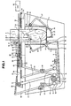
- a hook 1 is shown from which hangs by its leg joints 4 an item of dressed poultry 2 accommodated in a bag 3.
- the hook 1 is arranged to free itself from the leg joints 4 and thereafter to move upward by means provided therefor. Constructions which achieve these movements are described in published Dutch Patent Application No. 71.12520.
- the item of poultry 2 is supported on a downwardly foldable bottom member 5 which is pivotably mounted on a hinge-pin 6 and is able to jointly pivot with an arm 7 which is pivotably connected to a connecting-rod 8.
- This last mentioned integer is in turn pivotably coupled to a double-lever 9 which is pivotable about a fixed hinge-pin 10 and carries a cam-following roller 11 operatively engaging the periphery of a rotatable cam 12 (see fig. 2) affixed to a driven shaft 13.
- a shaft 14 pivotably carries three arms 15, 16 and 17 thereon, which arms are coupled in fixed relationship one to another.
- the arm 15 is connected to a coupling-rod 18 which is in turn connected to an arm 19 which is pivotably mounted on a fixed support member 20 and carries a cam-following roller 21.
- This cam-following roller 21 operatively engages the periphery of a cam 22 (see fig. 2).
- the arm 16 carries a forked-member 23 thereon.
- Another coupling-rod 24 is connected to the arm 17 and further connected to an arm 25 pivotably mounted on a fixed support member 26.
- the arm 25 is further connected to an arm-carrier 27 which accommodates a tension-spring 28.
- the forked-member 23 and the arm-carrier 27, with the tension-spring 28 which is provided with a covering to prevent pinching between the spirals thereof, are enabled to move in openings in the support plates 29 and 30 respectively under the action of the cam 22 which movements bring them into the positions indicated by the reference numerals 23' and 28' respectively at which positions they hold the item of poultry fast in the bag.
- a set of plates 31 and 32 are rigidly affixed to one another and arranged for horizontal displacement.
- a plate 33 lies therebetween and is horizontally displaceable in a direction reverse to that of the plates 31 and 32.
- the last mentioned pair of plates 31 and 32 and the plate 33 are provided with recesses 34 and 35 respectively of V-form on the sides thereof which are directed toward one another (see fig. 2).
- the plates 31 and 32 are carried by a horizontally movable member 36 having a coupling point 37 to which there is connected a coupling-rod 38 partially indicated by a chain-dotted line.
- the coupling-rod 38 is in turn connected to an arm 39 which can pivot about a fixed hinge-pin 40 and which carries a cam-following roller 41 on its outer end. This cam-following roller 41 operatively engages the periphery of the cam 42 (see also fig. 2 wherein the hinge-pin 40 has not been shown in the interests of clarity).
- the movable member 36 is carried by carriage 43 which can pivot on a fixed shaft 44 which is affixed to an arm 45 carrying a cam-following roller 46.
- This cam-following roller 46 operatively engages the periphery of the cam 47 (see fig. 2).
- the carriage 43 pivots from the position shown in fig. 1 to the position shown in fig. 3 and back again.
- the carriage 43 supports two freely rotatable sprocket-wheels or pulley-wheels 48 over which a chain 49 or belt is constrained to run (see fig. 2).
- Each of the chains or belts 49 is affixed to the plates 31 and 33 at the points 50 and 51 thereon respectively, and through which arrangement movement of the plate 31 (and thus also movement of plate 32) to the right leads to movement of the plate 32 to the left and vice-versa.
- the plates 53 and 54 of a pair of plates are arranged on a fixed carrier 52 for sliding displacement with respect thereto in the horizontal direction.
- the plate 53 is connected to a coupling-rod 56 shown partially as a chain-dotted line, at a connecting point 55 therefor.
- the coupling-rod 56 is pivotably connected in turn to an arm 57 which is also pivotable on a fixed hinge-pin 58 and which carries a cam-following roller 59 on its free-end, this cam-following roller 59 operatively engages the periphery of a cam 60 (see fig. 2).
- the second one of the plates, slidably mounted on the carrier 52 therefore and designated 54, is connected to a coupling-point 61 to which there is affixed a coupling-rod 62 partially indicated by a chain-dotted line.
- the coupling-rod 62 is connected to an arm 63 which can pivot about the hinge-pin coinciding with that indicated by the reference numeral 58 in figs. 1 and 3 and which carries a cam-following roller 64 at its free-end.
- the cam-following roller 64 operatively engages the periphery of the cam 65.
- the plates 53 and 54 are provided with recesses of V-form on the sides thereof directed toward one another, which recesses are indicated by the reference numerals 66 and 67 respectively (see fig. 2).
- Apparatus 68 of a known type is movably arranged above the plates 53 and 54.
- This apparatus 68 is equipped to close the bunched upper portion of a bag by application thereto of an adhesive tape or strip, and further to cut off that portion of the bag extending above the closed portion.
- Such apparatus is commercially obtainable.
- a block 69 carrying a pointed pin 70.
- This pin is enabled to slide in a hole through a divesting member 71 which is affixed to the carriage 43.
- fig. 5 graphically illustrates the rise, dwell and fall periods of the cams 12, 22, 42, 47, 60 and 65 which are obtainable due to the changes in the radial dimensions thereof during an operating cycle in which they rotate through an angle of 360°.
- the motions imparted to the hook 1 and the bag-closing apparatus 68 are indicated by the chain-lines designated b and g.
- the motions are not directly imparted from the cam shaft 13 but are synchronised to coincide with motions imparted to other members by the cams accommodated on this shaft.
- the line a in fig. 5 is representative of the motion imparted by cam 12 to forked-member 23 and the arm-carrier 27 carrying the tension-spring 28.
- the motion imparted by cam 12 causes the forked-arm 23 and the carrier-arm 27 to pivot inward to the positions indicated by the reference numerals 23' and 27' in fig. 1.
- no motion is imparted to the forked-member 23 and the carrier arm 27 and consequently these dwell in the positions indicated by the reference numerals 23' and 27'.
- the chain-line b is indicative of the upward movement of the hook 1 during the period in which the cam shaft 13 rotates from 25° to 50° during the rotation cycle of 360°, and which movement of the hook 1 takes place after its release from engagement with the leg joints 3 of the item of poultry. Since the members 23 and 27 firmly grip the legs of the item of poultry, the latter cannot be hoisted upward by the hook 1.
- Line c is indicative of the motion imparted by the cam 42 and shows that, during the period in which the cam 42 is rotated from 50° to 100°, the plates 31 and 32 on one side and plate 33 on the other are moved toward one another. On the termination of this movement of the last mentioned plates, they dwell in the positions to which they have been moved until the cam has rotated to 240°. Hereafter, these plates move apart to return to their initial positions during rotation of the cam 42 from 240° to 285°.
- this is indicative of the motion imparted by the cam 65 and shows that, during the period in which the cam 65 is rotated from 50° to 100°, the plate 54 is moved to its terminal position. After having achieved this movement, the plate 54 dwells in the terminal position until the cam 65 has rotated to 240°. Hereafter the plate 54 is moved back to its initial position during rotation of the cam 65 from 240° to 285°.
- this is in turn indicative of the motion imparted by cam 60 and shows that, during rotation of the cam 60 from 50° to 100°, the plate 53 is moved almost to its terminal position. Hereafter, the plate 53 dwells in this position during rotation of cam 60 from 100° to 185°. On further rotation of the cam 60 from 185° to 190°, the plate 53 moves the rest of the way to its terminal position in which position this plate dwells until the cam has rotated to 240°. The plate 53 returns to its initial position during further rotation of cam 60 from 240° to 285°.
- the line f is indicative of the motion imparted by the cam 47 in its action of pivoting the carriage 43 and shows that, during the period in which the cam 47 rotates from 100° to 145°, the carriage 43 is pivoted to its highest position and is maintained in this position during rotation of the cam 47 from 145° to 240°. Hereafter, the carriage 43 is pivoted back to its initial position through further rotation of the cam 47 from 240° to 285°.
- the chain-line g is indicative of the operation of the bag-closing apparatus 68 and in which the rise in the chain-line corresponds to a displacement leftward in figs. 1 and 2.
- the line h is indicative of the motion imparted by the cam 12 to the bottom member 5 and which action causes the latter to pivot downward during rotation of the cam 12 from 220° to 260°, thereafter to dwell in this downward pivoted position during rotation of the cam from 260° to 285° and after that to pivot the bottom member back upward to its initial position.
- the forked-member 23 and the arm-carrier 27 constituting the holding members come into operation.
- the hook 1 is pulled back.
- the set of plates 31 and 32 and the plate 33 move toward each other until they have completely bunched the upper portion of the bag together and firmly hold the bunched portion in this condition.
- the cam 47 is operative to pivot the carrier 43 upward.
- This action causes the bag to be pulled taut over its content and more so since the pointed portions of the recesses of V-form in the plates 31, 32 and 33 are just pushed over one another so that they very firmly grip the bag.
- the edges of the recesses of V-form can be rounded-off or chamfered at these locations.
- the pointed pin 70 pierces the upper end of the bag and this portion thereof remains hanging thereon when the apparatus 68 comes into operation to close the bag and sever the upper end free thereof.
- the apparatus has reached its initial operative condition from which a following operative cycle can be commenced once more.
Landscapes
- Engineering & Computer Science (AREA)
- Mechanical Engineering (AREA)
- Processing Of Meat And Fish (AREA)
- Package Closures (AREA)
Applications Claiming Priority (2)
| Application Number | Priority Date | Filing Date | Title |
|---|---|---|---|
| NL7900674 | 1979-01-29 | ||
| NLAANVRAGE7900674,A NL170938B (nl) | 1979-01-29 | 1979-01-29 | Inrichting voor het sluiten van een gevulde zak. |
Publications (2)
| Publication Number | Publication Date |
|---|---|
| EP0014021A1 EP0014021A1 (en) | 1980-08-06 |
| EP0014021B1 true EP0014021B1 (en) | 1983-08-31 |
Family
ID=19832537
Family Applications (1)
| Application Number | Title | Priority Date | Filing Date |
|---|---|---|---|
| EP80200072A Expired EP0014021B1 (en) | 1979-01-29 | 1980-01-25 | Bag closing apparatus |
Country Status (9)
| Country | Link |
|---|---|
| US (1) | US4328654A (da) |
| EP (1) | EP0014021B1 (da) |
| JP (1) | JPS55116539A (da) |
| AU (1) | AU538639B2 (da) |
| DE (1) | DE3064669D1 (da) |
| DK (1) | DK33380A (da) |
| ES (1) | ES8102035A1 (da) |
| IL (1) | IL59174A (da) |
| NL (1) | NL170938B (da) |
Families Citing this family (32)
| Publication number | Priority date | Publication date | Assignee | Title |
|---|---|---|---|---|
| US4554776A (en) * | 1982-02-19 | 1985-11-26 | Kabushiki Kaisha Daisei Kikai | Package bag binding apparatus |
| GB8314764D0 (en) * | 1983-05-27 | 1983-07-06 | Thurne Eng Co Ltd | Machine for closing filled bags |
| US4593516A (en) * | 1985-02-04 | 1986-06-10 | Robert Alameda | Apparatus for forming tight packages |
| CA1260884A (en) * | 1986-07-22 | 1989-09-26 | George Soga | Fused plastic bag closure and apparatus for making same |
| AUPM374694A0 (en) * | 1994-02-08 | 1994-03-03 | Taylor, Alfred Alexander | A packaging machine |
| JP2002511364A (ja) | 1998-02-10 | 2002-04-16 | エリクッソン、ビルホ | 管状容器を密閉するための装置及び方法 |
| US7775966B2 (en) | 2005-02-24 | 2010-08-17 | Ethicon Endo-Surgery, Inc. | Non-invasive pressure measurement in a fluid adjustable restrictive device |
| US7927270B2 (en) | 2005-02-24 | 2011-04-19 | Ethicon Endo-Surgery, Inc. | External mechanical pressure sensor for gastric band pressure measurements |
| US8066629B2 (en) | 2005-02-24 | 2011-11-29 | Ethicon Endo-Surgery, Inc. | Apparatus for adjustment and sensing of gastric band pressure |
| US8016744B2 (en) | 2005-02-24 | 2011-09-13 | Ethicon Endo-Surgery, Inc. | External pressure-based gastric band adjustment system and method |
| US7699770B2 (en) | 2005-02-24 | 2010-04-20 | Ethicon Endo-Surgery, Inc. | Device for non-invasive measurement of fluid pressure in an adjustable restriction device |
| US7775215B2 (en) | 2005-02-24 | 2010-08-17 | Ethicon Endo-Surgery, Inc. | System and method for determining implanted device positioning and obtaining pressure data |
| US7658196B2 (en) | 2005-02-24 | 2010-02-09 | Ethicon Endo-Surgery, Inc. | System and method for determining implanted device orientation |
| US8152710B2 (en) | 2006-04-06 | 2012-04-10 | Ethicon Endo-Surgery, Inc. | Physiological parameter analysis for an implantable restriction device and a data logger |
| US8870742B2 (en) | 2006-04-06 | 2014-10-28 | Ethicon Endo-Surgery, Inc. | GUI for an implantable restriction device and a data logger |
| US8187163B2 (en) | 2007-12-10 | 2012-05-29 | Ethicon Endo-Surgery, Inc. | Methods for implanting a gastric restriction device |
| US8100870B2 (en) | 2007-12-14 | 2012-01-24 | Ethicon Endo-Surgery, Inc. | Adjustable height gastric restriction devices and methods |
| US8142452B2 (en) | 2007-12-27 | 2012-03-27 | Ethicon Endo-Surgery, Inc. | Controlling pressure in adjustable restriction devices |
| US8377079B2 (en) | 2007-12-27 | 2013-02-19 | Ethicon Endo-Surgery, Inc. | Constant force mechanisms for regulating restriction devices |
| US8192350B2 (en) | 2008-01-28 | 2012-06-05 | Ethicon Endo-Surgery, Inc. | Methods and devices for measuring impedance in a gastric restriction system |
| US8337389B2 (en) | 2008-01-28 | 2012-12-25 | Ethicon Endo-Surgery, Inc. | Methods and devices for diagnosing performance of a gastric restriction system |
| US8591395B2 (en) | 2008-01-28 | 2013-11-26 | Ethicon Endo-Surgery, Inc. | Gastric restriction device data handling devices and methods |
| US7844342B2 (en) | 2008-02-07 | 2010-11-30 | Ethicon Endo-Surgery, Inc. | Powering implantable restriction systems using light |
| US8221439B2 (en) | 2008-02-07 | 2012-07-17 | Ethicon Endo-Surgery, Inc. | Powering implantable restriction systems using kinetic motion |
| US8114345B2 (en) | 2008-02-08 | 2012-02-14 | Ethicon Endo-Surgery, Inc. | System and method of sterilizing an implantable medical device |
| US8591532B2 (en) | 2008-02-12 | 2013-11-26 | Ethicon Endo-Sugery, Inc. | Automatically adjusting band system |
| US8057492B2 (en) | 2008-02-12 | 2011-11-15 | Ethicon Endo-Surgery, Inc. | Automatically adjusting band system with MEMS pump |
| US8034065B2 (en) | 2008-02-26 | 2011-10-11 | Ethicon Endo-Surgery, Inc. | Controlling pressure in adjustable restriction devices |
| US8233995B2 (en) | 2008-03-06 | 2012-07-31 | Ethicon Endo-Surgery, Inc. | System and method of aligning an implantable antenna |
| US8187162B2 (en) | 2008-03-06 | 2012-05-29 | Ethicon Endo-Surgery, Inc. | Reorientation port |
| US20140250832A1 (en) * | 2013-03-05 | 2014-09-11 | Chad V. Ciancio | Automatic Refuse Bag Release Device and Method of Using the Same |
| US11159033B2 (en) | 2019-04-10 | 2021-10-26 | Andrew Molle | Modular electric charging apparatus |
Family Cites Families (12)
| Publication number | Priority date | Publication date | Assignee | Title |
|---|---|---|---|---|
| US2899785A (en) * | 1959-08-18 | Gebhardt | ||
| US2627154A (en) * | 1949-04-29 | 1953-02-03 | Rose Brothers Ltd | Wrapping machinery |
| US2924924A (en) * | 1955-10-04 | 1960-02-16 | Wilson & Co Inc | Machine for packaging ham |
| US3175338A (en) * | 1962-05-23 | 1965-03-30 | Ahlgren Myron | Device for closing sacks or the like |
| NL6704453A (da) * | 1967-03-29 | 1968-09-30 | ||
| US3668818A (en) * | 1971-02-08 | 1972-06-13 | Kwik Lok | Semi-automatic closure applicator |
| DE2301817C3 (de) * | 1973-01-15 | 1983-11-03 | Sieg-Rheinische Registrierwaagenfabrik "fix" Peter Steimel, 5205 Hennef | Vorrichtung mit auf einem Kreisumfang angeordneten Stationen zum Herstellen von Seitenfaltensäcken aus einem Seitenfaltenschlauch |
| US3942302A (en) * | 1974-08-02 | 1976-03-09 | Bloom Max M | End closing machine for roll wrapped packages |
| US4107903A (en) * | 1976-02-03 | 1978-08-22 | Wickersheim & Johne Maschinen-Und Verpackungsanlagen Gmbh | Fully automatic device for packing piece goods, in particular fruits |
| IL51377A (en) * | 1977-02-02 | 1979-09-30 | Tzur Rochman | Machine for packaging chickens |
| US4125986A (en) * | 1977-10-27 | 1978-11-21 | Fmc Corporation | Bagging apparatus |
| US4223508A (en) * | 1978-03-16 | 1980-09-23 | The Kartridg Pak Co. | Double-knife cut-off for chub machine |
-
1979
- 1979-01-29 NL NLAANVRAGE7900674,A patent/NL170938B/xx not_active Application Discontinuation
-
1980
- 1980-01-16 US US06/112,476 patent/US4328654A/en not_active Expired - Lifetime
- 1980-01-21 IL IL59174A patent/IL59174A/xx unknown
- 1980-01-21 AU AU54779/80A patent/AU538639B2/en not_active Ceased
- 1980-01-25 DE DE8080200072T patent/DE3064669D1/de not_active Expired
- 1980-01-25 EP EP80200072A patent/EP0014021B1/en not_active Expired
- 1980-01-28 DK DK33380A patent/DK33380A/da not_active Application Discontinuation
- 1980-01-28 ES ES488349A patent/ES8102035A1/es not_active Expired
- 1980-01-29 JP JP922880A patent/JPS55116539A/ja active Pending
Also Published As
| Publication number | Publication date |
|---|---|
| JPS55116539A (en) | 1980-09-08 |
| EP0014021A1 (en) | 1980-08-06 |
| US4328654A (en) | 1982-05-11 |
| ES488349A0 (es) | 1980-12-16 |
| NL170938B (nl) | 1982-08-16 |
| AU5477980A (en) | 1980-08-07 |
| AU538639B2 (en) | 1984-08-23 |
| DE3064669D1 (en) | 1983-10-06 |
| IL59174A (en) | 1982-09-30 |
| DK33380A (da) | 1980-07-30 |
| NL7900674A (nl) | 1980-07-31 |
| ES8102035A1 (es) | 1980-12-16 |
Similar Documents
| Publication | Publication Date | Title |
|---|---|---|
| EP0014021B1 (en) | Bag closing apparatus | |
| US4324086A (en) | Wrapper closed with a U-shaped clip and process and apparatus for attaching a hanger loop to the wrapper section | |
| US4457124A (en) | Bag-packaging machine for bread | |
| EP0065802B1 (en) | Device for packing a fowl | |
| CN108750191A (zh) | 自动装箱机构及应用 | |
| JPH0632322A (ja) | 真空包装方法及び装置 | |
| CN109775348A (zh) | 一种自动餐饮设备 | |
| US3261143A (en) | Flexible bag closing machine | |
| US4149357A (en) | Device on a skein winding machine for applying bands | |
| US4551194A (en) | Taping machine for cartons of variable width | |
| CN108190112A (zh) | 一种适用于批量包装的具有矫正功能的全自动捆扎机 | |
| CA1151611A (en) | Method and apparatus for knotting automatically mouths of flexible packagings | |
| EP0028219B1 (fr) | Appareil chargeur automatique de sacs sur ensacheuses rotatives | |
| EP1212240B1 (en) | Apparatus for attaching a tag and a thread to a filter bag | |
| CN217012070U (zh) | 一种连续式自动捆绑机 | |
| CN216314408U (zh) | 菌包自动扎绳活动机构 | |
| EP0493852B1 (en) | Automatic machine and continuous thread system for tying poultry products | |
| US5448876A (en) | Machine for applying heat shrinkable bands to containers | |
| US3861114A (en) | Method of packaging | |
| US4036444A (en) | Apparatus for pneumatically separating a foot lap from a spinning cop | |
| ES455059A1 (es) | Dispositivo para enchufar sacos con valvula vacios sobre lostubos de llenado de una ensacadora rotativa. | |
| CN215794650U (zh) | 一种全自动打包机 | |
| JPS6238219B2 (da) | ||
| EP0778206A3 (en) | Automatic device for gripping and holding flexible bag-shaped containers and by means of independent gripping units | |
| JPH0585506A (ja) | 紐掛結び装置 |
Legal Events
| Date | Code | Title | Description |
|---|---|---|---|
| PUAI | Public reference made under article 153(3) epc to a published international application that has entered the european phase |
Free format text: ORIGINAL CODE: 0009012 |
|
| AK | Designated contracting states |
Designated state(s): BE DE FR GB IT |
|
| 17P | Request for examination filed |
Effective date: 19801127 |
|
| RAP1 | Party data changed (applicant data changed or rights of an application transferred) |
Owner name: ADMINISTRATIE- EN AUTOMATISERINGSCENTRUM VULCAAN |
|
| ITF | It: translation for a ep patent filed | ||
| GRAA | (expected) grant |
Free format text: ORIGINAL CODE: 0009210 |
|
| AK | Designated contracting states |
Designated state(s): BE DE FR GB IT |
|
| REF | Corresponds to: |
Ref document number: 3064669 Country of ref document: DE Date of ref document: 19831006 |
|
| ET | Fr: translation filed | ||
| PGFP | Annual fee paid to national office [announced via postgrant information from national office to epo] |
Ref country code: BE Payment date: 19831231 Year of fee payment: 5 |
|
| PGFP | Annual fee paid to national office [announced via postgrant information from national office to epo] |
Ref country code: FR Payment date: 19840201 Year of fee payment: 5 |
|
| PLBE | No opposition filed within time limit |
Free format text: ORIGINAL CODE: 0009261 |
|
| STAA | Information on the status of an ep patent application or granted ep patent |
Free format text: STATUS: NO OPPOSITION FILED WITHIN TIME LIMIT |
|
| 26N | No opposition filed | ||
| PGFP | Annual fee paid to national office [announced via postgrant information from national office to epo] |
Ref country code: DE Payment date: 19850130 Year of fee payment: 6 |
|
| PG25 | Lapsed in a contracting state [announced via postgrant information from national office to epo] |
Ref country code: BE Effective date: 19850131 |
|
| BERE | Be: lapsed |
Owner name: ADMINISTRATIE-EN AUTOMATISERINGSCENTRUM VULCAAN Effective date: 19850125 |
|
| GBPC | Gb: european patent ceased through non-payment of renewal fee | ||
| PG25 | Lapsed in a contracting state [announced via postgrant information from national office to epo] |
Ref country code: FR Free format text: LAPSE BECAUSE OF NON-PAYMENT OF DUE FEES Effective date: 19850930 |
|
| REG | Reference to a national code |
Ref country code: FR Ref legal event code: ST |
|
| PG25 | Lapsed in a contracting state [announced via postgrant information from national office to epo] |
Ref country code: DE Effective date: 19871001 |
|
| PG25 | Lapsed in a contracting state [announced via postgrant information from national office to epo] |
Ref country code: GB Effective date: 19881118 |