EP0014065B1 - Système pour créer un signal de servo-commande - Google Patents
Système pour créer un signal de servo-commande Download PDFInfo
- Publication number
- EP0014065B1 EP0014065B1 EP80300139A EP80300139A EP0014065B1 EP 0014065 B1 EP0014065 B1 EP 0014065B1 EP 80300139 A EP80300139 A EP 80300139A EP 80300139 A EP80300139 A EP 80300139A EP 0014065 B1 EP0014065 B1 EP 0014065B1
- Authority
- EP
- European Patent Office
- Prior art keywords
- signal
- digital
- analog signal
- during
- creating
- Prior art date
- Legal status (The legal status is an assumption and is not a legal conclusion. Google has not performed a legal analysis and makes no representation as to the accuracy of the status listed.)
- Expired
Links
Images




Classifications
-
- G—PHYSICS
- G05—CONTROLLING; REGULATING
- G05B—CONTROL OR REGULATING SYSTEMS IN GENERAL; FUNCTIONAL ELEMENTS OF SUCH SYSTEMS; MONITORING OR TESTING ARRANGEMENTS FOR SUCH SYSTEMS OR ELEMENTS
- G05B19/00—Program-control systems
- G05B19/02—Program-control systems electric
- G05B19/18—Numerical control [NC], i.e. automatically operating machines, in particular machine tools, e.g. in a manufacturing environment, so as to execute positioning, movement or co-ordinated operations by means of program data in numerical form
- G05B19/19—Numerical control [NC], i.e. automatically operating machines, in particular machine tools, e.g. in a manufacturing environment, so as to execute positioning, movement or co-ordinated operations by means of program data in numerical form characterised by positioning or contouring control systems, e.g. to control position from one programmed point to another or to control movement along a programmed continuous path
- G05B19/21—Numerical control [NC], i.e. automatically operating machines, in particular machine tools, e.g. in a manufacturing environment, so as to execute positioning, movement or co-ordinated operations by means of program data in numerical form characterised by positioning or contouring control systems, e.g. to control position from one programmed point to another or to control movement along a programmed continuous path using an incremental digital measuring device
- G05B19/25—Numerical control [NC], i.e. automatically operating machines, in particular machine tools, e.g. in a manufacturing environment, so as to execute positioning, movement or co-ordinated operations by means of program data in numerical form characterised by positioning or contouring control systems, e.g. to control position from one programmed point to another or to control movement along a programmed continuous path using an incremental digital measuring device for continuous-path control
- G05B19/251—Numerical control [NC], i.e. automatically operating machines, in particular machine tools, e.g. in a manufacturing environment, so as to execute positioning, movement or co-ordinated operations by means of program data in numerical form characterised by positioning or contouring control systems, e.g. to control position from one programmed point to another or to control movement along a programmed continuous path using an incremental digital measuring device for continuous-path control the positional error is used to control continuously the servomotor according to its magnitude
- G05B19/253—Numerical control [NC], i.e. automatically operating machines, in particular machine tools, e.g. in a manufacturing environment, so as to execute positioning, movement or co-ordinated operations by means of program data in numerical form characterised by positioning or contouring control systems, e.g. to control position from one programmed point to another or to control movement along a programmed continuous path using an incremental digital measuring device for continuous-path control the positional error is used to control continuously the servomotor according to its magnitude with speed feedback only
-
- G—PHYSICS
- G05—CONTROLLING; REGULATING
- G05B—CONTROL OR REGULATING SYSTEMS IN GENERAL; FUNCTIONAL ELEMENTS OF SUCH SYSTEMS; MONITORING OR TESTING ARRANGEMENTS FOR SUCH SYSTEMS OR ELEMENTS
- G05B2219/00—Program-control systems
- G05B2219/30—Nc systems
- G05B2219/34—Director, elements to supervisory
- G05B2219/34046—Analog multiplier
-
- G—PHYSICS
- G05—CONTROLLING; REGULATING
- G05B—CONTROL OR REGULATING SYSTEMS IN GENERAL; FUNCTIONAL ELEMENTS OF SUCH SYSTEMS; MONITORING OR TESTING ARRANGEMENTS FOR SUCH SYSTEMS OR ELEMENTS
- G05B2219/00—Program-control systems
- G05B2219/30—Nc systems
- G05B2219/41—Servomotor, servo controller till figures
- G05B2219/41021—Variable gain
Definitions
- the present invention relates to a system for controlling a remote servo device and more particularly to a system for creating a control signal for such a remote servo device.
- the invention is particularly applicable and will be described for controlling the position of a camera in response to sequentially stored digital information and it will be described with particular reference thereto; however, it is appreciated that the invention has broader applications and may be used in various types of servo systems wherein the instantaneous position of an output load of a servo device must be accurately controlled without interconnecting mechanical linkages and without following a corresponding, contemporaneously operated master unit.
- Control systems which coordinate movement with respect to more than one axis are used in other industries.
- U.S. Patent 3,731,175 to Hartung describes a control system primarily for use with machine tools.
- the system is concerned with maintaining proper alignment of a tool in two spatial dimensions.
- the system operates by supplying two control signals, S-1 and S-2, to a logic circuit at the beginning of an interval.
- S-1 has a value corresponding to the distance which must be travelled in the given (X) dimension during the interval.
- the binary coded signal is applied through AND gates to a register representing the velocity and where it is incremented by pulses representing the displacement of the actual tool.
- the output of this adder represents the instantaneous difference between the whole number of pulses S-1 and the pulses indicating distance thus far travelled by the tool.
- An error signal is provided.
- the error signal provided represents the difference between the present position of the tool and the position theoretically to be obtained at the end of the interval.
- the adder is not incremented to present a value of desired position which changes during the control interval. Desired positions are provided at the end of each interval and the control system moves to these points without intermediate position control.
- the system controls a remotely located electrical servo device by the use of stored data and with an improved synchronization of the servo device.
- the control system starts with a velocity control signal.
- This velocity control signal provides a velocity value which is applied to the control mechanism for a pre-selected time interval.
- the velocity control signal is augmented by a positional profile in controlling the movement of the slave unit or camera during each control interval.
- a positional profile is developed independent of the normal control mechanisms during the interval of constant velocity.
- the interval for which a constant velocity is specified which is normally sufficiently precise for control operations, is provided with a positional profile specifying the position of the slave unit at a plurality of times within the control interval.
- a starting position for the slave unit is contained in a position register. This starting position is incremented or decremented depending upon the velocity system controlling the velocity during the given interval.
- a position profile is provided within the small control interval. This is without the intervention of the larger control system which need only provide velocity information for each small interval.
- the desired position profile is compared with an actual position profile generated by a position encoder and stored in a current position register. This provides an error signal which is the difference between the desired position as provided by the position profile and the actual position.
- the position error signal is combined with a velocity signal providing precise control during each control interval and correcting for any small position error during the control interval.
- a digital word such as can be stored and successively outputted from a digital computer, can be used to control the desired velocity and the desired position during the short time intervals which are being processed at a given instance.
- a next digital word can then be created which will control the velocity and position signals during the next time interval.
- the servo device which receives a control signal is moved in unison with a plurality of successive binary stored data words.
- This type of stored data can be created on a tape, disc or other arrangement by numerical units or by actually reading the control function from a previously operated unit such as the foreground camera of a composite photographic system of the type illustrated in the two previously mentioned United States Letters Patents.
- the system preferably includes a digital register for storing a digital number representing the desired velocity for any given interval. This digital number may change from interval to interval to control the system in accordance with successively generated digital signals, which are converted to analog signals and summed.
- the desired time base positional profile against which the actual positional profile of the controlled servo device is compared is advantageously generated by a bi-directional digital counter of the up/down counting type.
- This counter is incremented or decremented periodically during the time interval to coordinate the desired position with the magnitude of the velocity signal being used to control the remote servo device.
- the actual time base positional profile is detected from the remote servo device and can be stored in a bi-directional counter for comparison with the desired or expected profile also stored in such a counter.
- the bi-directional current position counter is counted in one direction and when the output lead is moved in the opposite direction, the current position counter is counted in the opposite direction.
- a conventional bi-directional digital counter can be used to accurately indicate the exact, current position of a remote output load.
- any one of several types of encoders could be connected to the output load for determining the output position on the basis of the number contained in the current position counter.
- the direction of the velocity and the direction of the difference in the positional profiles can have an algebraic sign indicative of servo direction.
- the analog signal representing the desired velocity and the analog signal indicative of the offset of the actual position can be algebraically added to control the rate of movement of the controlled servo device.
- a plurality of time intervals are preferably created during which a coded digital signal is used to control the reference signal for a remote servo unit or device.
- a further analog control signal is created which is generally the difference between a desired position of the servo device and the actual position of the servo device.
- This positional analog difference signal may be created by a digital circuit having a first counter for creating a desired profile during a given time interval and a second counter for registering the actual position of the remote servo device as provided by an appropriate real time encoder.
- the system creates a controlled reference signal for a remote electrical servo device having a movable output unit or load, wherein the velocity and/or position of the output unit are controlled by the value of the control reference signal, which system provides accurate control of the remote load in accordance with a desired scheme formed as a series of successive, coded binary words.
- the system utilizes digital circuitry for controlling the analog input of the servo device in accordance with data available to the digital circuitry.
- the system does not require direct communication between the servo device and a master device.
- the system modifies the operation of the remote device by both an expected velocity and the actual position of the device during the operation of the invention.
- the system employs a series of successive, short time intervals during which the analog signal used to control the external or remote device is controlled by an externally created data signal.
- the system employs short time intervals and controls the motion of the remote device by a different magnitude during successive time intervals.
- the system uses digital circuitry to produce a fixed and variable analog signal which are combined to create a control signal for the remote servo device.
- the system is operative by a series of stored words of digital data to control analog signals in successive intervals during which the data is stored for use by the system.
- the system modifies the desired position of the remote device during a time interval while the desired velocity of the device remains the same so that the system tracks a velocity controlled servo with a positional modulating or attenuating signal.
- system A includes a remotely located servo unit or device B having certain components which are somewhat standard and a control circuit or module C which is partially illustrated for the purposes of simplicity.
- Remote servo unit or device B includes a D.C. motor M which moves the load L in each of two opposite directions, be it angular, linear or combinations thereof.
- the motor shaft also drives a tachometer T having an electric output which is proportional to the speed of motor M. This concept is in accordance with standard servo mechanism practice.
- An optical shaft encoder E provides quadrature incremental position pulses when a portion of the encoder is rotated by the shaft of motor M.
- the encoder provides information on the position of the motor and load L in line 36.
- a servo error preamplifier 10 amplifies the difference between the desired servo velocity which is an analog signal appearing on line 12 and the actual servo velocity which is an analog signal appearing on line 14 under the control of tachometer T.
- the difference between these two analog signals is applied to a standard motor driving amplifier 20 which controls the speed of motor M so that the output of the tachometer closes the servo loop to allow the load to be moved in accordance with the analog voltage on input line 12.
- circuitry C for each movement to be applied to an appropriate external load L.
- Each of these circuits or modules, as illustrated in Figure 1 includes a desired velocity signal in line 22, which signal changes periodically from one time frame or time interval to the next. Of course, adjacent intervals could have the same velocity signal if that is the desired operation of remote device B. Thus, a fixed analog signal appears in line 22 but the signal may change from time interval to time interval. The resolution of the system can be controlled by changing the length of the time interval. In practice, when used in a motion picture system the time frame has a length of time correlated to the time spacing of a single film frame.
- the resolution may be substantially different; however, the time interval or time frame is generally less than about 30 seconds.
- the time frame or interval can be varied substantially to obtain the desired motion of load L in response to operation of module C.
- the analog signal representing the desired velocity during a given time frame or time interval is applied to a standard summing circuit or amplifier S having a second input analog signal on line 24 from a digital difference circuit 30.
- This circuit will be described in more detail with respect to Figure 8 wherein the circuit is divided into sub-components 30a, 30b which record a digital difference and convert this digital difference to an analog signal for application on line 24.
- the difference circuit 30 receives two digital inputs.
- the first digital input is a desired position which changes during the time frame or time interval and generally corresponds to the desired position of load L at various positions of the time frame or interval being processed.
- This desired or expected position for load L is applied to circuit 30 through a plurality of lines represented as single line 32.
- the output of encoder E which detects actual position of load L is digitized and applied to difference circuit 30 through a plurality of lines indicated as a single line 34.
- the analog signal in line 24 applied to summing circuit S is an analog representative of the difference between the actual or current position of load L with respect to the expected or desired position of this load as stored and modified within module 30 and independent of remote device B.
- control circuit or module C is operated by stored digital data as opposed to a master which is the normal procedure for controlling the movement of a remote servo device. Any one of various procedures could be employed for obtaining the desired data for use by circuit C.
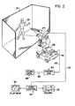
- Figure 2 which generally corresponds to the foreground camera system illustrated in prior United States Letters Patents 3,902,798 and 3,914,540 which are incorporated by reference herein.
- the foreground camera is used to photograph on a color masked stage an actor which produces a portion of a composite photographic picture and which creates electrical signals indicative of the movement of several elements involved in the positioning of the camera with respect to the stage.
- stage 10 has a color that does not record and an actor 52 performs on this stage.
- Foreground camera 54 is carried by dolly 56 on a boom 58.
- Operator 60 controls the camera which causes movement of the boom, movement of the camera and movement of the dolly.
- control data is created by the foreground camera of a composite photograph system as shown in Figure 2, it can be used in controlling a background camera 80 movable on a control stand 82 and directed through a periscope 83 toward a reduced scaled scene 84, as shown in Figure 3.
- Camera 80 is movable in the three orthogonal directions X, Y, Z and can be tilted or panned with respect to scene 84 in accordance with the previously recorded data indicative of the movement of foreground camera 54.
- Each of the movements of camera 80 is controlled by a single module C so that lines 12, 36 are duplicated in accordance with the desired number of movements of camera 80 with respect to scene 84.
- Appropriate digital data is loaded by unit 90 into control circuit C in accordance with a procedure which will be described later.
- the data in unit 90 is created in unit 68 and is a series of digital words indicative of the desired velocity of camera 80 during a succession of pre-selected time intervals.
- various other arrangements could be provided for creating the desired control signals or words which are processed in accordance with the present invention which will be described later.
- a video line 92 is directed to a video control unit 94 which combines the play back 96 from tape unit 76 with the video signal in line 92 to provide a composite display in unit 98 and a composite recording in unit 99.
- a video control unit 94 which combines the play back 96 from tape unit 76 with the video signal in line 92 to provide a composite display in unit 98 and a composite recording in unit 99.
- FIG. 4 a general block diagram of a system employing the present invention is illustrated.
- stored data in unit 100 is provided with a plurality of digital words indicative of the desired velocity of load L which is illustrated as a camera as the camera is moved along a single axis.
- a standard digital computer 102 uses the stored data and transmits the stored data in succession and in parallel to circuit or module C for use in successive time frames or time intervals to move camera L with respect to an appropriate object 104 along axis X.
- Figure 4 shows a single axis control arrangement.
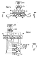
- FIG 5 another representative system is employed wherein two control circuits C1, C2 are controlled by digital computer 102a from words in stored data unit 100a so that remote controls B1, B2 can move loads L1, L2.
- load L1 could be a foreground camera
- load L2 could be a background camera wherein the words to the foreground camera and background camera have a built-in geometric relationship as explained with respect to the previous United States Letters Patents.
- Figure 5 illustrates a system wherein two control circuits C1, C2 constructed in accordance with the present invention controls two separate remote loads L1, L2.
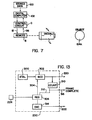
- FIG 6 three separate control circuits C3-C5 are used to control three loads L3-L5 each of which controls the movement of a single unit, such as a camera 110, photographing an object 104b. Consequently, a control module C constructed in accordance with the present invention can be used to control movement of a remote object. If more than one object is to be moved, a control circuit or module can be used for each object. If a single element is to be moved in several directions, a separate control or module circuit C can be used for each axis and direction. If the present invention is to be used for rotating or panning a device, this can be done and is schematically illustrated in Figure 7 wherein load L is a camera directed toward an object 104c. Remote unit C is used to rotate camera L in the angular direction indicated by the arrow in Figure 7 in a manner that the camera is moved in a single direction in Figure 4.
- control units or control circuits C as previously described is constructed in accordance with the present invention as shown in detail in Figure 8.
- circuit C which may be one or more separate components supporting boards.
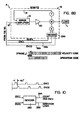
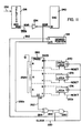
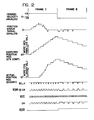
- circuit or module C includes a system controller 200 which generates a series of signals as set forth in Figure 13.
- these signals could be created directly by the computer, by a controller especially when the controller 200 is of the programmable controller type or by a combination thereof.
- various necessary, somewhat standard types of controlling pulses and a system clock or clocks are created by the joint action of the computer 102 and controller 200.
- These control signals operate the invention which relates to a manner for using the controller and computer information and not to the function of these components themselves.
- the digital control information used in the present invention may be supplied by various components. As shown in the lower left hand corner of Figure 8, some of the more basic signals employed in the preferred embodiment of the invention are illustrated. These signals are a reset pulse for the numerical controlled oscillator 210 which appears in line 210a, a clear pulse for the current position register or counter 212 appearing in line 212a, a load pulse for the desired or expected position register or counter 214 appearing in line 214a, and a load pulse for the velocity register which appears in line 218. These pulses are used to sequence the preferred embodiment of the invention in a manner to be explained later.
- Numerical controlled oscillator 210 which is reset by a pulse in line 210a, receives the velocity i.e. delta position word in digital form for the specific time interval or frame being processed. Thereafter, a pulse train is created in output line 250 which adds or subtracts in binary fashion from the content of the expected or desired position register 214.
- the current position register 212 is a 20 bit register which may be up counted or down counted and includes a digital representation of the current position as controlled and updated by pulses from encoder E of remote device B.
- the previously mentioned desired or expected position register 214 is a 20 bit register which may be up counted or down counted in accordance with standard digital practice.
- comparator 30a can be a standard 20 bit digital adder which adds the actual position to the 2's complement expected position to form a difference which is the absolute or algebraic positional error value in digital form.
- other digital comparing arrangements could be used. If the 2's complement were not used, a direct digital comparison could be made with various systems, such as a comparing gate network, to determine the amount of difference between the current position of load L as stored in one register and the desired position as stored in another register.
- a digital code representing desired position change is stored in 12 bit velocity register 216.
- the numerical controlled oscillator 210 updates the desired position during the time frame in accordance with the magnitude and sign of the stored velocity code in line 232. This provides desampling during each frame or timing interval.
- the positional error signal in line 24 is changed while a generally fixed velocity signal in line 22 is being directed to the summing amplifier S during a single time interval.
- the numerical controlled oscillator 210 updates the digital comparing circuit during a time frame having a length determined by pulses from system controller 200. During each time frame only a single velocity code is contained within a 12 bit velocity register 216; therefore, the velocity signal in line 22 remains fixed.
- system controller 200 as shown in Figure 13 creates a system clock on line 220.
- This clock is used to provide the input clocking rate for numerical controlled oscillator 210.
- the system controller creates time scaling, a gain level or multiplier signal for a standard 12 bit multiplying 2's complement digital to analog converter 240 by creating an analog signal in line 222 as shown in Figure 13.
- This analog signal and the clock are directly coordinated by the system controller 200 so that as the clock in line 220 increases the analog gain signal in line 222 increases proportionally.
- the spacing between the starting pulses or loading pulses in line 218 for register 216 are inversely proportional to these two signals from the system controller.
- Controller 200 receives data from a storage register 224 which indicates the length of the current frame or timing interval being processed by system A. As the time frame is decreased, the reference to converter 240 is increased and the frequency of the clocking pulses to oscillator 210 is increased. Thus, system A is changed to operate at different time intervals which are coordinated by system controller 200. If a more accurate movement is required, a smaller time frame or time interval is used by system A. The length of the time frame is generally modified for each successive time frame.
- a digital delta position signal of 12 bits is directed to velocity register 216 from the computer 102 which receives the information from the stored data unit 100. Since the 2's complement coding is used in this system, the most significant bit provides the sign or direction for the operation during a given time interval.
- the magnitude and sign of the velocity code for a given time interval is directed to converter 240 which produces a pre- selected fixed analog signal in line 22. The magnitude of this signal is determined by the digital coding of the velocity bits together with the gain control in line 222 in accordance with standard operating practices for such a converter. Thus, a fixed, expected or desired velocity analog signal is maintained in line 22 as a given time interval is being processed.
- the summing amplifier S is modulated during a time interval by the difference between the actual or current position of load L during the time frame as stored in register 212 on a system created reference in register 214.
- the digitized current position information of register 212 is compared to the desired or expected position created by module C in register 214 by any appropriate digital comparing technology.
- the digitized expected or desired position changes during the time frame at a rate controlled by the magnitude of the velocity code in register 216.
- the sign of the change is controlled by the most significant bit of the velocity code in register 216.
- the register containing the digitized expected position is incremented or decremented according to the sign and at a rate determined by the velocity code for a given time frame being processed.
- Circuit or module C employs a digital arrangement for indicating a velocity for a very short time interval, which velocity is used as a reference for the error amplifier 10 in a remote unit B.
- a digital updated desired position of register 214 is compared with a digital actual position of load L in register 212 to indicate changes in the actual operation of device B. This slight change is used to create an analog difference signal in line 24 which is summed with the analog velocity signal in line 22 to provide the desired final control analog signal in line 12.
- the basic component of this arrangement is the velocity register 216 which is a 12 bit register that receives 2's complement data along twelve data lines shown as a single line 230.
- a pulse in line 218 from function decoder 202 loads the 2's complement 12 bit data information for a given time frame into register 216.
- the output of this register is twelve lines shown as a single line 232.
- the most significant bit in this group of lines includes the sign or direction logic which appears in line 232a after it is inverted by inverter 234.
- the logic in this most significant bit line 232a controls the sign of the circuit C during a time frame and is directed to the standard B1 terminal of converter 240.
- this terminal is a sign or direction terminal to indicate the sign or direction of the analog signal in line 22.
- the most significant bit has a logic which determines whether the number is a positive or a negative number.
- the negative velocity indicates that the motor M is to rotate in one direction and a positive velocity indicates that the motor is to rotate in the opposite direction.
- the gain or reference line 222 from system controller 200 and the logic of the velocity bits applied to converter 240 determines the magnitude of the analog velocity signal within line 22 for any given time frame between pulses in line 218.
- the sign or direction is controlled by the log on line 232a. As the next pulse occurs in line 218, a new code is selected from stored data unit 100 and directed through line 230 to register 216.
- a prescribed analog signal is applied to line 22 which remains fixed during the time interval. If the time interval or frame is to have a modified time length, a code is received from register 224 by controller 200. This changes the gain in line 222 and the system clock in line 220 as has been described. These changes in the length of the time interval are not affected by the code being loaded into register 216. Other arrangements could be provided for digitally controlling the analog signal in line 22.
- the velocity code is as a series of twelve bit words which are sequentially outputted from computer 102.
- An operation word or code is provided as needed and causes any desired operation from frame to frame or during initialization, such as resetting and loading certain registers.
- the operation code can indicate the gain and clocking rate to be used during a given frame or time interval.
- circuit C provides an analog signal on line 22 which is to be added to the analog signal in line 24 for controlling error amplifier 10 of remote unit B.
- line 22 includes an analog signal which is controlled by digital circuitry to give the difference between the actual position of motor M and its load L and a desired or expected position as modified by the pulses in line 250 during a given time frame or time interval.
- the desired or expected position is changed in a direction and rate determined by the velocity code for any given time frame or interval.
- the twenty bit register 214 is loaded with the 2's complement of a desired position which position changes during the time frame by counting pulses in line 250.
- the numerical controlled oscillator 210 receives the velocity code in lines 232 and the timing clock in line 220 from. system controller 200.
- the velocity code and clocking rate determines the pulsing rate in line 250.
- pulses in line 250 change proportionately.
- the clocking rate in line 220 is changed only to modify the length of the timing interval.
- the direction of counting for register 214 is controlled by the sign logic on line 232a as has been previously described.
- the direction of counting by pulses in line 250 is controlled by the sign of the velocity code during a time frame being processed.
- register 214 is counted in a first direction. If the velocity code is in the opposite sign direction, the counter is counted in the opposite direction.
- counter or register 214 can determine the desired position from the start to finish of a time frame during which the velocity code remains the same. This, therefore, recognizes the fact that during a time frame having a fixed velocity control analog signal, the position of the motor will change as indicated by the modification of the digital number in register 214.
- a register 214 is loaded with the desired starting position for operation of system A. This signal is in 2's complement coding and is loaded into register 214 at the start of a given operation cycle of system A.
- a digital representation of the actual position of load L is stored in current position register 212, which is a twenty bit register.
- the outputs of this register control the logic on twenty lines represented by a single line 34. These bits are compared with twenty bits on the corresponding lines, represented as line 32, from register 214. These two logics are then compared by an appropriate device, indicated as adder 30a.
- Encoder E provides an index pulse at a selected point in the movement of load L. This pulse is used to determine the relative position of the components at the start of a given cycle so that the expected position can be appropriately selected with respect to the existing position at the initialization of the system A. This is in accordance with standard encoder practice.
- Encoder E also provides an in- phase pulse ENCI on line 36a and a quadrature pulse ENCQ on line 36b. These two lines are directed from remote unit C to a decoder 290 in circuit C. This decoder determines the relationship between the encoder pulses to determine the direction of movement of load L by motor M, as shown schematically in Figure 10. Pulses for each increment of movement are also created by decoder 290 which pulses may be the pulses on line 36a if desired. The actual movement direction for a given time frame is the logic contained on output line 292, which line is connected to the direction terminal of current position register 212. Pulses are then directed to the counting terminal C of register 212 from decoder 290 through line 294. Thus, register 212 is counted up or counted down according to the actual direction of movement of load L with respect to the fixed index point. The signals from the encoder are directed to circuit C through drivers 295.
- FIG. 9 a relatively simplified flow chart is illustrated to show the general operation of system A.
- the current position is located with respect to the index point provided by encoder E.
- the expected position for the first frame is determined and loaded into register 255.
- the pulse in line 214a then loads the expected position in 2's complement coding into register 214.
- a pulse in line 212a clears the current position register. This provides a starting point at the beginning of a cycle so that the current position register and desired position register are correlated in 2's complement fashion to provide essentially no difference in output line 24 of the difference circuit 30.
- system A cycles circuit or module C through time frames, each of which provides an arrangement to fetch a velocity code from the data stored in unit 100.
- This data is then loaded into register 216 at the same time that the gain and clock information is fetched and stored into register 224 controlling the time frame parameters of system controller 200. After a selected time frame, data is incremented for the next time frame. After a predetermined number of time frames, the cycle of system A is stopped.
- any number of digital circuits could be used for creating an analog difference signal which is the difference between the actual position determined by an encoder and an expected position determined by a counter which is updated during a timing frame or timing interval by the magnitude of velocity being used during that interval.
- the 2's complement coding is used for register 214 so that an adder circuit 30a can be employed to produce a difference signal.
- the numerical controlled oscillator for controlling the pulse rate in line 250 can take the component form as shown in Figure 11 wherein updating line 250 provides the counting pulses in both the up and down directions for the register 214.
- a cascaded group of three summing networks is provided with the carry line 262 being connected to one input of an EXCLUSIVE OR gate 264 having an output 266.
- Quad-latches 270, 272, 274 circulate the output sum of the summing networks back to the B terminals of the networks in circuit 260 so that a clocking pulse from the system clock 220 causes an overflow at line 262 at a rate determined by the code on lines 232b.
- These lines are the velocity code excluding the most significant bit which controls the logic on line 232a.
- the sum of each summing network is latched into the B terminals of one of the latches to upcount the summing networks until there is a count overflow.
- a schematic layout of the preferred system controller 200 is illustrated.
- one system controller can operate more than one module C.
- a crystal controlled oscillator 300 with pulses gated through a numerical controlled oscillator 302 by the code on a series of lines represented as a single line 304 which are the output lines or terminals of a register 306.
- This register receives a code indicating the length of the time frame.
- the pulses in line 220 are counted by a binary counter 310 to stop the pulses in line 220 by resetting register 306 through line 312.
- the counting rate of pulses in line 220 is changed.
- the gain signal in line 222 is also changed with length of the time frame. This is done in practice by a digital to analog converter 314 of the type previously described.
- the code in register 306 during a selected frame controls the gain signal in line 222 for the purpose previously described.
- Counter 310 also produces a signal in line 316 to inform the computer C that a frame has been completed.
- the controlled unit progresses to a position determined by the velocity word in register 216 at a rate selected by controller 200.
- System A shown in Figures 1 and 8 provides a velocity error correction feature.
- the servo damping tachometer T provides a feedback signal which introduces a velocity lag error.
- the signal in line 22 is a constant level during a time frame. This signal in line 22 provides an estimate of the derivative of motion which tends to offset the like error signal in line 14 from the tachometer.
- the system shown in Figures 1 and 8 in one sense uses the velocity estimation signal from converter 240, to provide basic wideband (fast response) control over the controlled velocity servo unit B with a lower bandwidth (slower response) digital correcting signal in line 24. Because of the wideband motion estimation control of the signal in line 22, velocity, acceleration and higher order lag errors are substantially minimized in system A.
- the numerical controlled oscillator 210 as shown in Figure 11, provides uniformly spaced pulses as shown in Figure 12 when either counting up or counting down the spacing changes with the velocity code and the system time frame. At the junction between time frames pulses are spaced to prevent close occurrence of the last pulse of one time frame and the first pulse of the next time frame.
- oscillator 210 retains the partial count or phase for count completion later.
- This characteristic of the preferred embodiment implies phase coherency from frame-to-frame. During processing of a given sequence, the time frame or interval is changed to provide increased exposure time as a camera approaches its subject, when system A is used for photographic purposes.
Landscapes
- Engineering & Computer Science (AREA)
- Human Computer Interaction (AREA)
- Manufacturing & Machinery (AREA)
- Physics & Mathematics (AREA)
- General Physics & Mathematics (AREA)
- Automation & Control Theory (AREA)
- Control Of Position Or Direction (AREA)
- Feedback Control In General (AREA)
Claims (25)
Applications Claiming Priority (2)
| Application Number | Priority Date | Filing Date | Title |
|---|---|---|---|
| US06/003,742 US4245298A (en) | 1979-01-15 | 1979-01-15 | System for creating a servo control signal |
| US3742 | 1995-09-14 |
Publications (2)
| Publication Number | Publication Date |
|---|---|
| EP0014065A1 EP0014065A1 (fr) | 1980-08-06 |
| EP0014065B1 true EP0014065B1 (fr) | 1983-12-21 |
Family
ID=21707364
Family Applications (1)
| Application Number | Title | Priority Date | Filing Date |
|---|---|---|---|
| EP80300139A Expired EP0014065B1 (fr) | 1979-01-15 | 1980-01-15 | Système pour créer un signal de servo-commande |
Country Status (5)
| Country | Link |
|---|---|
| US (1) | US4245298A (fr) |
| EP (1) | EP0014065B1 (fr) |
| JP (1) | JPS5595111A (fr) |
| CA (1) | CA1127743A (fr) |
| DE (1) | DE3001012C2 (fr) |
Families Citing this family (18)
| Publication number | Priority date | Publication date | Assignee | Title |
|---|---|---|---|---|
| US4398241A (en) * | 1980-08-07 | 1983-08-09 | The Singer Company | Digital control circuit for an analog servo |
| US4498129A (en) * | 1981-07-02 | 1985-02-05 | Irwin Magnetic Systems, Inc. | Method and apparatus for normalizing servo-positioning signals |
| JPS5983217A (ja) * | 1982-11-04 | 1984-05-14 | Nippon Kogaku Kk <Nikon> | 位置決め装置 |
| JPS59107884A (ja) * | 1982-12-10 | 1984-06-22 | 株式会社日立製作所 | ロボツトの制御方式 |
| JPS59177604A (ja) * | 1983-03-28 | 1984-10-08 | Fanuc Ltd | 数値制御方法 |
| GB8319892D0 (en) * | 1983-07-23 | 1983-08-24 | Ae Plc | Machine tool control |
| US4577271A (en) * | 1983-08-15 | 1986-03-18 | International Cybernetics Corporation | Sampled data servo control system |
| US4523137A (en) * | 1983-09-27 | 1985-06-11 | Mechatron Systems, Inc. | Dual mode printer servo with improved velocity signal generator |
| US4701839A (en) * | 1984-11-09 | 1987-10-20 | International Cybernetic Corporation | Sampled data servo control system with field orientation |
| US4714400A (en) * | 1986-04-14 | 1987-12-22 | Ibm Corporation | Plural robotic drive |
| DE3718066A1 (de) * | 1987-05-29 | 1988-12-08 | Zeiss Carl Fa | Verfahren zur mikroinjektion in zellen bzw. zum absaugen aus einzelnen zellen oder ganzer zellen aus zellkulturen |
| US5589901A (en) * | 1995-05-15 | 1996-12-31 | Means; Kevin P. | Apparatus and method for synchronizing search and surveillance devices |
| CN101060301A (zh) * | 2006-04-22 | 2007-10-24 | 中山大洋电机股份有限公司 | 电子换向电机的速度控制选择方法及选择电路 |
| US7460774B2 (en) * | 2006-06-21 | 2008-12-02 | Optoelectronics Co., Ltd. | Method to control image stabilizer |
| DE102007022631B3 (de) * | 2007-05-11 | 2008-12-18 | Phoenix Contact Gmbh & Co. Kg | Parametierungsüberwachung für analoge Signalbaugruppen |
| US10968676B2 (en) * | 2018-04-24 | 2021-04-06 | Gmi Holdings, Inc. | Movable barrier apparatus and methods for responding to barrier travel obstructions and abnormalities |
| US11803168B2 (en) | 2019-03-08 | 2023-10-31 | General Electric Company | Distributed control modules with cumulating command references |
| US11746584B2 (en) | 2019-04-24 | 2023-09-05 | Gmi Holdings, Inc. | Remote monitoring and control of moveable barrier in jackshaft door operator system |
Family Cites Families (16)
| Publication number | Priority date | Publication date | Assignee | Title |
|---|---|---|---|---|
| FR1232912A (fr) * | 1956-11-13 | 1960-10-12 | Ibm France | Perfectionnements aux dispositifs d'asservissement |
| DE1273043B (de) * | 1962-11-29 | 1968-07-18 | Cincinnati Milling Machine Co | Lageregelkreis mit einem reversiblen Antriebsmotor und einem unterlagerten Drehzahlregelkreis |
| DE2008204C3 (de) * | 1970-02-21 | 1974-06-12 | Tokyo Seimitsu Sokki K.K., Kanagawa (Japan) | Vorrichtung zur Steuerung von mehrdimensionalen Bewegungsabläufen |
| US3752969A (en) * | 1971-09-24 | 1973-08-14 | Allen Bradley Co | Method and means for updating the position dimension of a numerically controlled machine tool |
| US3731175A (en) * | 1972-03-06 | 1973-05-01 | Xerox Corp | Servo system for velocity and position control |
| US3828168A (en) * | 1972-03-31 | 1974-08-06 | Eaton Corp | Controlled velocity drive |
| US3887122A (en) * | 1973-01-02 | 1975-06-03 | Hyper Loop | Press feeder control apparatus |
| US3941987A (en) * | 1973-09-04 | 1976-03-02 | Danly Machine Corporation | Method and apparatus for numerical control |
| US3902798A (en) * | 1974-03-15 | 1975-09-02 | Magicam Inc | Composite photography system |
| US3970830A (en) * | 1974-06-24 | 1976-07-20 | Cone-Blanchard Machine Company | Computer controlled machine tool contouring system |
| US3914540A (en) * | 1974-10-03 | 1975-10-21 | Magicam Inc | Optical node correcting circuit |
| US3917930A (en) * | 1974-11-25 | 1975-11-04 | Cincinnati Milacron Inc | Method and apparatus for adaptively positioning a machine element |
| US3987282A (en) * | 1975-04-22 | 1976-10-19 | Redactron Corporation | Shaft position controlling system |
| US4084083A (en) * | 1975-11-05 | 1978-04-11 | Contraves Goerz Corporation | Multi-axis electronic motion generator |
| US4086522A (en) * | 1976-09-08 | 1978-04-25 | Unimation, Inc. | Computer assisted teaching arrangement for conveyor line operation |
| US4146922A (en) * | 1977-08-29 | 1979-03-27 | Ncr Corporation | Constant velocity driving means |
-
1979
- 1979-01-15 US US06/003,742 patent/US4245298A/en not_active Expired - Lifetime
-
1980
- 1980-01-12 DE DE3001012A patent/DE3001012C2/de not_active Expired
- 1980-01-14 JP JP299780A patent/JPS5595111A/ja active Pending
- 1980-01-14 CA CA343,586A patent/CA1127743A/fr not_active Expired
- 1980-01-15 EP EP80300139A patent/EP0014065B1/fr not_active Expired
Also Published As
| Publication number | Publication date |
|---|---|
| JPS5595111A (en) | 1980-07-19 |
| US4245298A (en) | 1981-01-13 |
| CA1127743A (fr) | 1982-07-13 |
| EP0014065A1 (fr) | 1980-08-06 |
| DE3001012A1 (de) | 1980-07-17 |
| DE3001012C2 (de) | 1985-01-03 |
Similar Documents
| Publication | Publication Date | Title |
|---|---|---|
| US4245298A (en) | System for creating a servo control signal | |
| US5457370A (en) | Motion control system for cinematography | |
| US4086522A (en) | Computer assisted teaching arrangement for conveyor line operation | |
| US3512060A (en) | Machine tool control system | |
| JP3805057B2 (ja) | レンズ装置 | |
| US4101774A (en) | X-ray system having a driving mechanism for an x-ray source and an x-ray detector | |
| EP0080374B1 (fr) | Méthode et dispositif de mesure de la position réelle dans un système de commande de position | |
| EP0273052B1 (fr) | Dispositif detecteur de la position rotative du rotor d'un moteur | |
| JPS63148881A (ja) | サ−ボモ−タの速度制御装置 | |
| US3523229A (en) | Digital-analog servo system | |
| US3896361A (en) | Method and apparatus for compensating an error in numerical control | |
| JPS6346843B2 (fr) | ||
| US3569814A (en) | Programmed digital servo control including repeated command updating whereby output function becomes smoothly varying | |
| EP0999700B1 (fr) | Dispositif de prise de vue avec plate-forme rotative | |
| US4170415A (en) | System for producing orthophotographs | |
| US3893011A (en) | Numerical control system controlling a machine and provided with a system for compensating a position-error in the numerical control of the machine | |
| US4095157A (en) | Digital servomechanism control system | |
| JPS6232804B2 (fr) | ||
| US3757188A (en) | Error correction for incremental plotter | |
| US5231340A (en) | Servomotor control method | |
| Koren et al. | Numerical control of a lathe | |
| JPS621012A (ja) | 回転体の位置決め制御装置 | |
| JP2570039B2 (ja) | 移動位置校正装置 | |
| JP2730314B2 (ja) | ロボットの制御装置 | |
| JPS6161125B2 (fr) |
Legal Events
| Date | Code | Title | Description |
|---|---|---|---|
| PUAI | Public reference made under article 153(3) epc to a published international application that has entered the european phase |
Free format text: ORIGINAL CODE: 0009012 |
|
| AK | Designated contracting states |
Designated state(s): FR GB IT |
|
| 17P | Request for examination filed |
Effective date: 19801020 |
|
| ITF | It: translation for a ep patent filed | ||
| GRAA | (expected) grant |
Free format text: ORIGINAL CODE: 0009210 |
|
| AK | Designated contracting states |
Designated state(s): FR GB IT |
|
| ET | Fr: translation filed | ||
| PLBE | No opposition filed within time limit |
Free format text: ORIGINAL CODE: 0009261 |
|
| STAA | Information on the status of an ep patent application or granted ep patent |
Free format text: STATUS: NO OPPOSITION FILED WITHIN TIME LIMIT |
|
| 26N | No opposition filed | ||
| ITTA | It: last paid annual fee | ||
| PGFP | Annual fee paid to national office [announced via postgrant information from national office to epo] |
Ref country code: GB Payment date: 19981215 Year of fee payment: 20 |
|
| PGFP | Annual fee paid to national office [announced via postgrant information from national office to epo] |
Ref country code: FR Payment date: 19981230 Year of fee payment: 20 |
|
| PG25 | Lapsed in a contracting state [announced via postgrant information from national office to epo] |
Ref country code: GB Free format text: LAPSE BECAUSE OF EXPIRATION OF PROTECTION Effective date: 20000114 |
|
| REG | Reference to a national code |
Ref country code: GB Ref legal event code: PE20 Effective date: 20000114 |