EP0014121B1 - Appareil de chauffage à micro-ondes - Google Patents
Appareil de chauffage à micro-ondes Download PDFInfo
- Publication number
- EP0014121B1 EP0014121B1 EP80400045A EP80400045A EP0014121B1 EP 0014121 B1 EP0014121 B1 EP 0014121B1 EP 80400045 A EP80400045 A EP 80400045A EP 80400045 A EP80400045 A EP 80400045A EP 0014121 B1 EP0014121 B1 EP 0014121B1
- Authority
- EP
- European Patent Office
- Prior art keywords
- chamber
- microwave
- dielectric
- conveyor
- sources
- Prior art date
- Legal status (The legal status is an assumption and is not a legal conclusion. Google has not performed a legal analysis and makes no representation as to the accuracy of the status listed.)
- Expired
Links
Images


Classifications
-
- H—ELECTRICITY
- H01—ELECTRIC ELEMENTS
- H01Q—ANTENNAS, i.e. RADIO AERIALS
- H01Q19/00—Combinations of primary active antenna elements and units with secondary devices, e.g. with quasi-optical devices, for giving the antenna a desired directional characteristic
- H01Q19/06—Combinations of primary active antenna elements and units with secondary devices, e.g. with quasi-optical devices, for giving the antenna a desired directional characteristic using refracting or diffracting devices, e.g. lens
- H01Q19/08—Combinations of primary active antenna elements and units with secondary devices, e.g. with quasi-optical devices, for giving the antenna a desired directional characteristic using refracting or diffracting devices, e.g. lens for modifying the radiation pattern of a radiating horn in which it is located
-
- H—ELECTRICITY
- H05—ELECTRIC TECHNIQUES NOT OTHERWISE PROVIDED FOR
- H05B—ELECTRIC HEATING; ELECTRIC LIGHT SOURCES NOT OTHERWISE PROVIDED FOR; CIRCUIT ARRANGEMENTS FOR ELECTRIC LIGHT SOURCES, IN GENERAL
- H05B6/00—Heating by electric, magnetic or electromagnetic fields
- H05B6/64—Heating using microwaves
- H05B6/72—Radiators or antennas
-
- H—ELECTRICITY
- H05—ELECTRIC TECHNIQUES NOT OTHERWISE PROVIDED FOR
- H05B—ELECTRIC HEATING; ELECTRIC LIGHT SOURCES NOT OTHERWISE PROVIDED FOR; CIRCUIT ARRANGEMENTS FOR ELECTRIC LIGHT SOURCES, IN GENERAL
- H05B6/00—Heating by electric, magnetic or electromagnetic fields
- H05B6/64—Heating using microwaves
- H05B6/78—Arrangements for continuous movement of material
-
- H—ELECTRICITY
- H05—ELECTRIC TECHNIQUES NOT OTHERWISE PROVIDED FOR
- H05B—ELECTRIC HEATING; ELECTRIC LIGHT SOURCES NOT OTHERWISE PROVIDED FOR; CIRCUIT ARRANGEMENTS FOR ELECTRIC LIGHT SOURCES, IN GENERAL
- H05B2206/00—Aspects relating to heating by electric, magnetic, or electromagnetic fields covered by group H05B6/00
- H05B2206/04—Heating using microwaves
- H05B2206/046—Microwave drying of wood, ink, food, ceramic, sintering of ceramic, clothes, hair
Definitions
- the present invention relates to microwave heating apparatus for processing material enclosed in an evacuated chamber.
- Magnetrons of such high power have a narrow limitation on the allowable amount of power that may reenter them, either as a reflection of the magnetrons' own output or as "cross-talk" from other magnetrons in the system. It has been suggested by some to use circulators to avoid this problem; however, circulators are relatively expensive and they do not solve other problems that accompany high power delivery into a microwave chamber. Also, where vacuum drying is carried out simultaneously with microwave heating, it is very difficult to prevent ionization of gas in the chamber by the microwave electric fields. Ionization permits arcing that wastes the microwave energy and, it can also degrade the quality of the process material and is generally destructive of the apparatus.
- Some of the objects of the present invention are to overcome these problems of non-uniform high power, discontinuous heating, reflection into the magnetrons, as well as cross-talk. Another object is to reduce ionization and arcing problems where microwaves are used within an evacuated chamber.
- the uniform distribution of continuous high microwave power into the process material is accomplished by radiating, preferably at regular places along the inside of the chamber, defined beams of circularly polarized microwave radiation, each beam being directed to illuminate a prescribed portion of the process material or a prescribed area through which the process material is moved.
- Microwave beams are weaker near their edges than at the center and so they are overlapped to compensate for this and provide illumination that is essentially uniform across the width of the path of the process material. Overlapping may also be effective to compensate for non-uniform distribution of the process material on the conveyor.
- the illumination does not depend upon the use of mode stirrers or turntables or any other equipment designed to reflect the microwave energy about the chamber and it does not depend particularly upon the geometry of the chamber. It permits the chamber to be designed in view of the pressure or vacuum conditions of operation: For example, it permits-a cylindrical chamber which is the preferred shape for withstanding vacuum and still provide for the spatially extended continuous processing of the subject materials on a conveyor belt.
- a structure is provided so that the peak values of electric fields of the microwave energy at a window where the microwave energy enters the chamber from the ambient pressure exterior are severely limited.
- high intensity microwave electric fields are produced at the "bottle neck" where the microwave is transmitted from the exterior region through some sort of microwave transparent, pressure withstanding window, into the evacuated interior of the chamber.
- the intensity of the electric fields is usually much lower and ionization problems are reduced.
- a cylindrical microwave chamber is provided through which a conveyor belt moves the process material at about the. center of the cylinder.
- a conveyor belt moves the process material at about the. center of the cylinder.
- separate sources radiate beams of microwave energy into the chamber, directed toward the process material.
- Each beam illuminates a prescribed area of the conveyor belt and the beams overlap particularly along the center of the belt so as to produce a uniform or an intentionally “tailored” heating pattern.
- the configuration of each beam is modified by a dielectric lens that redirects the microwave energy just before it enters the chamber through the window and directs the beam toward the conveyor.
- Another design feature that contributes to uniform heating is to provide separate microwave power sources for the sources that are not mutually coherent.
- each of the individual beams is generated outside of the chamber, re-directed by the lens and radiated into the chamber through a transparent window at the chamber wall.
- a transparent window at the chamber wall.
- the window is a half wave length of the microwave in thickness to minimize reflections from the window.
- the area of the window is made as large as practical, the beam radiated through it is predominantly TE mode waves rather than TM mode waves and is essentially a single mode beam rather than a mixture of modes and the single mode is circularly polarized.
- One advantage of circular polarization is that twice as much power is transmitted as for a plane polarized beam for a given peak value of the microwave electric field.
- Vertical orientation of the sources on top of the cylindrical chamber also facilitates changing the direction of a beam so that the beam therefrom can be directed to one side or the other of vertical and so pointed as needed at one region or another of the conveyor.
- the vertical orientation of sources can be along the axial plane of symmetry of the cylindrical chamber and conveyor therein; or the sources can be set off to either side of that plane by the effect of a prism lens, and send skewed beams toward the conveyor.
- the skewed beam does not define a figure of revolution and does not illuminate the conveyor uniformally everywhere it strikes, but equal skewed beams from opposite sides of that plane can balance each other and even provide combined illumination that is uniform across the conveyor.
- the chamber is defined by the chamber wall 12 that is electrically conductive. It is cylindrical in shape, because that shape is intrinsically strong and best able to withstand the pressures produced on the chamber when it is evacuated as, for example, in a microwave heating and vacuum drying process.
- a conveyor belt 21 Within the chamber is a conveyor belt 21, a section of which is shown in the Figures, positioned substantially at the center of the chamber and extending longitudinally therethrough.
- the conveyor belt carries the process material 22 usually distributed evenly along and across the belt.
- each beam is preferably of substantially uniform intensity across the beam-prior to entering the cylindrical chamber-and is circularly polarized. Furthermore, where the beams enter the cylindrical chamber, defined by walls 12, through an opening 13 in the chamber, the beam substantially completely fills that opening. As shown in Figures 1 and 2, the beams are defined by broken lines and are denoted 24, 26 and 28 along the left side of the chamber, and 25 along the right side of the chamber. Each beam preferably overlaps the adjacent beams and so insures that along this microwave heating section of the chamber substantially the whole area of the conveyor belt 21 is illuminated by the sources. Furthermore, by overlapping the beams, the tendency is to compensate for the reduced intensity of radiation at the edges of the beams.
- each of the beams is from a different source wherein the microwave energy is generated, converted to a linearly polarized TE mode, then converted to circular polarization, spread, redirected and radiated into the chamber.
- the separate sources, denoted 34, 36 and 38 .on the left side and 35, on the right (one for each beam), may be constructed - su.bstantially identical to each other as a matter of convenience..
- the process material is carried through the microwave heating section shown in Figures 1 and 2 on the conveyor belt and heated by the direct radiation of the beams.
- the process material is primarily heated by the first pass of microwave energy from the microwave sources and there is no primary dependance upon reflections of the microwave energy within the chamber to direct it to the process material.
- microwave mode stirrers within the chamber.
- each beam is derived from a different source, and there is no phase coherence between the beams; so, again, there is no need for mode stirrers within the chamber.
- there is no direct radiation from one source into another source and since the radiation is circularly polarized, a negligible amount of radiation from any source that may reflect within the chamber will reenter the same or any - other source.
- the beams 24, 26, 28 and 25 respectively are produced by sources 34, 36, 38 and 35 respectively. These sources may be constructed substantially all the same and so only one of them, source 34, is described in detail herein below.
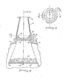
- the source consists of a microwave power generator, a mode-forming launcher, a polarization convertor, a conical expansion in diameter, and an assembly, which includes a sealed transparent dielectric window in the chamber and a dielectric lens.
- the microwave power generator is a,magnetron 1.
- the coaxial output section 2 from the magnetron terminates in a probe 4 that feeds a standard waveguide section 3, also called a launcher, that launches the microwave energy into the waveguide and thence into the polarizing and beam-forming portions of the source.
- the polarizing section of the source includes a quarter wavelength transformer section 5 between the launcher 3 and the polarization converter 6.
- the converter 6 consists of a square waveguide and means, denoted 7, within the square waveguide for converting linearly polarized radiation from the launcher into circularly polarized radiation.
- the microwave radiation flowing out of the converter 6 is circularly polarized and flows into the top end of conical wave guide coupling 8 that contains a dielectric lens 9 at the wide circular bottom end thereof.
- the lens is immediately adjacent and above the dielectric window 10 that is of minimally larger diameter than the lens, in order to be captive in and sealed to holder 19 that, in turn, seals to cylindrical chimney 11, connected directly to an opening 13 in the wall ofthe chamber 12.
- Suitable flanges at 14,15,16,17 and 18 connect these various parts and sections together as shown in the Figures. All of these flanges must provide contiguous conductive connections between the parts to insure ideal operation without arcing or leakage of microwave energy or mode transformation. In addition, flange 18 must seal against the vacuum within the chamber when the equipment is used for vacuum drying and microwave heating and, as mentioned above, the window must be sealed to its holder 19.
- the curve 9a of the dielectric lens, the electrical thickness of the dielectric window 10 and the dimensions of the cylindrical chimney 11 are all designed to produce the particular beam direction and shape that is desired. More particularly, it is generally desired that the beam 24 from source 34 be directed to illuminate an area of the conveyor 21 that begins at the outside edge 21 a of the conveyor and extends across the conveyor past the center at 21 b. Similarly, beacon 35 produces the beam 25 that illuminates the conveyor from the opposite edge 21 c somewhat past the middle at 21 b; and so at the middle, where the two beams 24 and 25 are weaker, they overlap to some wxtent. This insures complete illumination from side 21 a to side 21 b of the conveyor.
- Source 35 can be constructed identical to beacon 34, but would be a mirror image of it, as viewed in Figure 1. Thus, these sources tend to produce beams directed radially inward from the edge of the cylindrical chamber 12 toward the center of the chamber and the subsequent pairs of sources 36 and 37 and 38 and 39 do the same.
- sources 34, 36 and 38 can be constructed identical to each other and sources 35, 37 and 39 can be constructed identical to each other and the even numbered sources are mirror images of the odd numbered sources.
- Figures 3 and 4 show details of construction of the polarization converter 6. It consists of a square wave guide section 6a in which are mounted dielectric plates 7a and 7b contiguous to each other across a diagonal of the square. These plates are longitudinally staggered along the length of the square wave guide. They are the same length, (L1 plus L2) and one is staggered ahead of the other by the dimensions L2. L1 is of such a length that: where and m is greater than n.
- X'g is wavelength with only plate 7a or 7b.
- ⁇ "g is with both plates 7a and 7b.
- Subscript ⁇ is with electric field perpendicular to the plates.
- Subscript 11 is with electric field parallel the plates.
- the dielectric prism lens 9 may be constructed as illustrated by Figures 5, 6 and 7.
- the experimentally shaped curve 9a-of this lens is established by a stack of dielectric plates 9a' to 9j, shown in the side cross section view by Figures 5 and a plan view by Figures.7.
- the purpose of the dielectric lens in the source is to re-directthe beam emerging from the conical wave guide 8, to be skewed toward the center of the chamber.
- This prism lens structure is clearly not a figure of revolution about the beacon axis 30. It is symmetrical with respect to the plane through the beacon axis, perpendicular to the chamber axis.
- the thickness of this lens varies around the edge or periphery of the stack. Thus, it is generally prism- shaped. It is thicker at the inside edge toward the chamber plane of symmetry 23, than at its edge away from plane 23. The effect of this lens is to redirect the beam to one side of the beacon axis 30, toward the center 21 b of the conveyor in the chamber.
- the dielectric lens is immediately adjacent dielectric window 10.
- the -thickness D of the window is one half wave length of the microwave radiation in the dielectric material of which the window is made.
- the conical wave guide connects to the dielectric window holder 19 by flange 17 and the window holder connects to the cylindrical chimney 11 by flange 18.
- the window seals to the chimney by an 0-ring gasket vacuum seal 20 and so the interior of the chamber is vacuum sealed from the exterior ambient and is also sealed from the source structure.
- the holder 19 provides electrical continuity between the wide end of the conical wave guide and the cylindrical chimney 11.
- microwave currents conducted by the conical wave guide 8, holder 19 and chimney 11 bound the propagating fields of the microwave energy that flows into the cylindrical treatment chamber 12, and is radiated as the beam 24.
- the beam of microwave radiation is substantially all in a single TE mode, circularly polarized and fully blankets the dielectric window.
- the instantaneous peak value of the microwave electric field at the dielectric window on the vacuum side (the chamber side) is maintained low. It is maintained sufficiently low that it does not cause ionization of the gas inside the chamber even at the low operating pressures desirable for vacuum drying.
- FIG. 8 Another dielectric lens structure is shown by Figures 8 and 9.
- This structure is symmetrical with respect to all planes through the beacon axis 30. It defines a figure of revolution about the axis 30 and so that axis of the pattern of radiation that defines the beam issuing from this lens is a continuation of the axis 30.
- This lens is spheroidal and has no prism. Using this. lens to direct the beam toward the center of the conveyor may require that the source be located or oriented with its axis toward the center of the conveyor and so the source axis would be substantially radial with respect to the cylindrical chamber in which the center of the conveyor is at the center of the chamber cylinder.
- Beacons each with a lens constructed as in Figures 8 and 9 are preferably all in line along the cylindrical chamber directly above the conveyor and so all such beacons would have the beacon axis in the symmetrical plane 23 of the cylindrical chamber.
- This lens is made up of a stack of dielectric plates 31 a, b, c each being ring-shaped. The outer peripheries of these plates are all about the same and their inner peripheries are successively larger and so the stack defines the dielectric lens curve 32 and spreads the radiation into a wider directional beam directed along the source axis 30.
- the embodiment of the invention described hereinabove includes and incorporates all of the features of the invention and this embodiment is capable of microwave heating of materials in a continuous process, while, at the same tjme, (or at least in the same chamber), exposing the materials to a low pressure for vacuum drying.
- the apparatus is suitable for microwave heating and vacuum drying and many of the features of construction provide an advantage for both heating by microwaves and vacuum drying.
- This apparatus is also usable in a discontinuous process.
Landscapes
- Physics & Mathematics (AREA)
- Electromagnetism (AREA)
- Constitution Of High-Frequency Heating (AREA)
- Drying Of Solid Materials (AREA)
Claims (10)
Applications Claiming Priority (2)
| Application Number | Priority Date | Filing Date | Title |
|---|---|---|---|
| US518679A | 1979-01-22 | 1979-01-22 | |
| US5186 | 1979-01-22 |
Publications (2)
| Publication Number | Publication Date |
|---|---|
| EP0014121A1 EP0014121A1 (fr) | 1980-08-06 |
| EP0014121B1 true EP0014121B1 (fr) | 1987-04-22 |
Family
ID=21714600
Family Applications (1)
| Application Number | Title | Priority Date | Filing Date |
|---|---|---|---|
| EP80400045A Expired EP0014121B1 (fr) | 1979-01-22 | 1980-01-14 | Appareil de chauffage à micro-ondes |
Country Status (2)
| Country | Link |
|---|---|
| EP (1) | EP0014121B1 (fr) |
| DE (1) | DE3071956D1 (fr) |
Families Citing this family (11)
| Publication number | Priority date | Publication date | Assignee | Title |
|---|---|---|---|---|
| GB2164796B (en) * | 1981-09-17 | 1986-11-12 | Itt Ind Ltd | Semiconductor processing |
| GB8511049D0 (en) * | 1985-05-01 | 1985-06-12 | Shell Int Research | Apparatus for uniform microwave bulk heating |
| SE451228B (sv) * | 1985-12-30 | 1987-09-14 | Stiftelsen Inst Mikrovags | Mikrovagsapplikator for verming av fremst vesentligen strengformade eller langstreckta kroppar |
| GB2187618B (en) * | 1986-03-06 | 1989-11-15 | Quindicum Ltd | Microwave oven |
| DE19855555C2 (de) * | 1998-12-02 | 2001-03-15 | Linn High Therm Gmbh | Heizeinrichtung |
| JP3293069B2 (ja) * | 1999-05-28 | 2002-06-17 | エリー株式会社 | 被加熱物の加熱方法及びその装置 |
| WO2005079116A2 (fr) * | 2004-02-11 | 2005-08-25 | Micro Heat Limited | Procede et appareil de chauffage d'une charge fluidique par energie radiofrequence |
| DE102006034084B4 (de) * | 2006-07-20 | 2023-07-06 | Muegge Gmbh | Anordnung zur Konzentration von Mikrowellenenergie |
| MX2012007766A (es) | 2010-01-18 | 2012-08-01 | Enwave Corp | Secado al vacio de materiales organicos por medio de microondas. |
| DE102010053791A1 (de) * | 2010-12-08 | 2012-06-14 | Karlsruher Institut für Technologie | Mikrowellenquelle sowie Werkzeug umfassend eine Mikrowellenquelle |
| US20120160839A1 (en) | 2010-12-23 | 2012-06-28 | Eastman Chemical Company | Microwave wood heater with enhanced spatial usage efficiency and uniformity of heat distribution |
Family Cites Families (7)
| Publication number | Priority date | Publication date | Assignee | Title |
|---|---|---|---|---|
| US2599864A (en) * | 1945-06-20 | 1952-06-10 | Robertson-Shersby-Ha Rob Bruce | Wave front modifying wave guide system |
| US2480682A (en) * | 1946-09-21 | 1949-08-30 | Raytheon Mfg Co | Microwave heating apparatus using circularly polarized horn |
| US2603741A (en) * | 1946-12-12 | 1952-07-15 | Goodrich Co B F | High-frequency heating |
| DE832026C (de) * | 1948-10-02 | 1952-02-21 | Siemens & Halske A G | Aus Hohlleitern aufgebaute Linse fuer elektromagnetische Wellen |
| US2801412A (en) * | 1953-07-22 | 1957-07-30 | Paul C Maybury | Radio frequency antenna |
| FR2275961A1 (fr) * | 1974-06-21 | 1976-01-16 | Anvar | Four tunnel a chauffage hyperfrequence |
| CA1038936A (fr) * | 1974-09-16 | 1978-09-19 | Tibor S. Laszlo | Transporteur d'alimentation anti-fuite pour appareil a micro-ondes |
-
1980
- 1980-01-14 EP EP80400045A patent/EP0014121B1/fr not_active Expired
- 1980-01-14 DE DE8080400045T patent/DE3071956D1/de not_active Expired
Also Published As
| Publication number | Publication date |
|---|---|
| EP0014121A1 (fr) | 1980-08-06 |
| DE3071956D1 (en) | 1987-05-27 |
Similar Documents
| Publication | Publication Date | Title |
|---|---|---|
| EP0014121B1 (fr) | Appareil de chauffage à micro-ondes | |
| EP1013150B1 (fr) | Applicateur hyperfrequence tubulaire | |
| KR101289771B1 (ko) | 마이크로파 플라즈마원 및 플라즈마 처리 장치 | |
| US5517085A (en) | Apparatus including ring-shaped resonators for producing microwave plasmas | |
| US7806077B2 (en) | Plasma nozzle array for providing uniform scalable microwave plasma generation | |
| EP1276356B1 (fr) | Dispositif de traitement au plasma | |
| CA1173512A (fr) | Systeme d'alimentation pour produire des ondes electromagnetiques polarisees elliptiquement dans un four a microondes | |
| US20110315678A1 (en) | Microwave heating device | |
| EP0486943B1 (fr) | Dispositif pour l'excitation d'un champ à micro-ondes uniforme | |
| CA2221697A1 (fr) | Applicateur hyperfrequence cylindrique avec pieces rotatives | |
| US6863773B1 (en) | Linearly extended device for large-surface microwave treatment and for large surface plasma production | |
| CA2235648A1 (fr) | Dispositif d'excitation d'un gaz au moyen de plasma d'onde de surface et un appareil de traitement du gaz incorporant un tel dispositif | |
| CA2096893A1 (fr) | Guide d'ondes pour four a micro-ondes | |
| WO2019041576A1 (fr) | Système d'alimentation d'antenne à rayonnement uniforme bidirectionnel | |
| JPS5923123B2 (ja) | マイクロ・ストリツプライン・アンテナ装置 | |
| JP2006040609A (ja) | プラズマ処理装置および方法、並びにフラットパネルディスプレイ装置の製造方法 | |
| US3715555A (en) | Circular waveguide microwave applicator | |
| JPS6366038B2 (fr) | ||
| KR20160140388A (ko) | 플라즈마 처리 장치 | |
| KR20010051358A (ko) | 유전 가열 장치 | |
| RU2085057C1 (ru) | Сверхвысокочастотная печь | |
| US20100126987A1 (en) | Device for transfer of microwave energy into a defined volume | |
| KR100275968B1 (ko) | 전자레인지의 도파관 시스템 | |
| JPH08330065A (ja) | マイクロ波解凍加熱装置 | |
| WO1991003140A1 (fr) | Applicateur de micro-ondes |
Legal Events
| Date | Code | Title | Description |
|---|---|---|---|
| PUAI | Public reference made under article 153(3) epc to a published international application that has entered the european phase |
Free format text: ORIGINAL CODE: 0009012 |
|
| AK | Designated contracting states |
Designated state(s): BE CH DE FR GB IT NL SE |
|
| 17P | Request for examination filed |
Effective date: 19810727 |
|
| R17P | Request for examination filed (corrected) |
Effective date: 19810206 |
|
| RIN1 | Information on inventor provided before grant (corrected) |
Inventor name: WHITE, JEROME R. Inventor name: THUERY, JACQUES |
|
| RAP1 | Party data changed (applicant data changed or rights of an application transferred) |
Owner name: PREMO FRANCE S.A.R.L. |
|
| GRAA | (expected) grant |
Free format text: ORIGINAL CODE: 0009210 |
|
| AK | Designated contracting states |
Kind code of ref document: B1 Designated state(s): BE CH DE FR GB IT NL SE |
|
| REF | Corresponds to: |
Ref document number: 3071956 Country of ref document: DE Date of ref document: 19870527 |
|
| ET | Fr: translation filed | ||
| ITF | It: translation for a ep patent filed | ||
| REG | Reference to a national code |
Ref country code: CH Ref legal event code: PUE Owner name: JD-TECHNOLOGIE AG C/O GESTINOR SERVICES AG |
|
| RAP2 | Party data changed (patent owner data changed or rights of a patent transferred) |
Owner name: JD-TECHNOLOGIE AG |
|
| REG | Reference to a national code |
Ref country code: FR Ref legal event code: TP |
|
| REG | Reference to a national code |
Ref country code: GB Ref legal event code: 732 |
|
| NLT2 | Nl: modifications (of names), taken from the european patent patent bulletin |
Owner name: JD-TECHNOLOGIE AG TE ZUG, ZWITSERLAND. |
|
| BECH | Be: change of holder |
Free format text: 870422 *JD-TECHNOLOGIE A.G. |
|
| PLBE | No opposition filed within time limit |
Free format text: ORIGINAL CODE: 0009261 |
|
| STAA | Information on the status of an ep patent application or granted ep patent |
Free format text: STATUS: NO OPPOSITION FILED WITHIN TIME LIMIT |
|
| 26N | No opposition filed | ||
| NLS | Nl: assignments of ep-patents |
Owner name: JD-TECHNOLOGIE AG TE ZUG, ZWITSERLAND. |
|
| PGFP | Annual fee paid to national office [announced via postgrant information from national office to epo] |
Ref country code: NL Payment date: 19890131 Year of fee payment: 16 |
|
| REG | Reference to a national code |
Ref country code: GB Ref legal event code: 732 |
|
| ITTA | It: last paid annual fee | ||
| PGFP | Annual fee paid to national office [announced via postgrant information from national office to epo] |
Ref country code: GB Payment date: 19920114 Year of fee payment: 13 |
|
| PGFP | Annual fee paid to national office [announced via postgrant information from national office to epo] |
Ref country code: DE Payment date: 19920120 Year of fee payment: 13 |
|
| PGFP | Annual fee paid to national office [announced via postgrant information from national office to epo] |
Ref country code: FR Payment date: 19920122 Year of fee payment: 13 |
|
| PGFP | Annual fee paid to national office [announced via postgrant information from national office to epo] |
Ref country code: SE Payment date: 19920127 Year of fee payment: 13 |
|
| PGFP | Annual fee paid to national office [announced via postgrant information from national office to epo] |
Ref country code: CH Payment date: 19920206 Year of fee payment: 13 |
|
| PGFP | Annual fee paid to national office [announced via postgrant information from national office to epo] |
Ref country code: BE Payment date: 19920212 Year of fee payment: 13 |
|
| PG25 | Lapsed in a contracting state [announced via postgrant information from national office to epo] |
Ref country code: GB Effective date: 19930114 |
|
| PG25 | Lapsed in a contracting state [announced via postgrant information from national office to epo] |
Ref country code: SE Effective date: 19930115 |
|
| PG25 | Lapsed in a contracting state [announced via postgrant information from national office to epo] |
Ref country code: BE Effective date: 19930131 Ref country code: CH Effective date: 19930131 |
|
| BERE | Be: lapsed |
Owner name: JD-TECHNOLOGIE A.G. Effective date: 19930131 |
|
| PG25 | Lapsed in a contracting state [announced via postgrant information from national office to epo] |
Ref country code: NL Effective date: 19930801 |
|
| GBPC | Gb: european patent ceased through non-payment of renewal fee |
Effective date: 19930114 |
|
| NLV4 | Nl: lapsed or anulled due to non-payment of the annual fee | ||
| PG25 | Lapsed in a contracting state [announced via postgrant information from national office to epo] |
Ref country code: FR Effective date: 19930930 |
|
| REG | Reference to a national code |
Ref country code: CH Ref legal event code: PL |
|
| PG25 | Lapsed in a contracting state [announced via postgrant information from national office to epo] |
Ref country code: DE Effective date: 19931001 |
|
| REG | Reference to a national code |
Ref country code: FR Ref legal event code: ST |
|
| EUG | Se: european patent has lapsed |
Ref document number: 80400045.3 Effective date: 19930810 |