EP0014128A1 - Vorrichtung zur Gewährleistung eines elektrischen und thermischen Kontaktes zwischen mehreren metallischen Oberflächen, und deren Verwendung - Google Patents
Vorrichtung zur Gewährleistung eines elektrischen und thermischen Kontaktes zwischen mehreren metallischen Oberflächen, und deren Verwendung Download PDFInfo
- Publication number
- EP0014128A1 EP0014128A1 EP80400058A EP80400058A EP0014128A1 EP 0014128 A1 EP0014128 A1 EP 0014128A1 EP 80400058 A EP80400058 A EP 80400058A EP 80400058 A EP80400058 A EP 80400058A EP 0014128 A1 EP0014128 A1 EP 0014128A1
- Authority
- EP
- European Patent Office
- Prior art keywords
- frame
- wire
- armature
- axis
- thermal contact
- Prior art date
- Legal status (The legal status is an assumption and is not a legal conclusion. Google has not performed a legal analysis and makes no representation as to the accuracy of the status listed.)
- Granted
Links
- 239000002184 metal Substances 0.000 claims abstract description 49
- 229910052751 metal Inorganic materials 0.000 claims abstract description 49
- 238000000034 method Methods 0.000 claims abstract description 16
- 238000004804 winding Methods 0.000 claims abstract description 6
- 238000004519 manufacturing process Methods 0.000 claims description 15
- 238000006073 displacement reaction Methods 0.000 abstract description 3
- 238000009423 ventilation Methods 0.000 description 5
- 230000002787 reinforcement Effects 0.000 description 4
- 229910000906 Bronze Inorganic materials 0.000 description 3
- 239000010974 bronze Substances 0.000 description 3
- KUNSUQLRTQLHQQ-UHFFFAOYSA-N copper tin Chemical compound [Cu].[Sn] KUNSUQLRTQLHQQ-UHFFFAOYSA-N 0.000 description 3
- 238000003466 welding Methods 0.000 description 3
- 229910052790 beryllium Inorganic materials 0.000 description 2
- ATBAMAFKBVZNFJ-UHFFFAOYSA-N beryllium atom Chemical compound [Be] ATBAMAFKBVZNFJ-UHFFFAOYSA-N 0.000 description 2
- -1 polytétrafluoroéthylène Polymers 0.000 description 2
- 229910001369 Brass Inorganic materials 0.000 description 1
- 240000008042 Zea mays Species 0.000 description 1
- 239000010951 brass Substances 0.000 description 1
- 238000001816 cooling Methods 0.000 description 1
- 238000010438 heat treatment Methods 0.000 description 1
- 238000009434 installation Methods 0.000 description 1
- 239000011810 insulating material Substances 0.000 description 1
- 239000000463 material Substances 0.000 description 1
- 239000004033 plastic Substances 0.000 description 1
- 229920001343 polytetrafluoroethylene Polymers 0.000 description 1
- 239000004810 polytetrafluoroethylene Substances 0.000 description 1
- 239000011253 protective coating Substances 0.000 description 1
- WFKWXMTUELFFGS-UHFFFAOYSA-N tungsten Chemical compound [W] WFKWXMTUELFFGS-UHFFFAOYSA-N 0.000 description 1
- 239000010937 tungsten Substances 0.000 description 1
- 229910052721 tungsten Inorganic materials 0.000 description 1
Images


Classifications
-
- H—ELECTRICITY
- H01—ELECTRIC ELEMENTS
- H01P—WAVEGUIDES; RESONATORS, LINES, OR OTHER DEVICES OF THE WAVEGUIDE TYPE
- H01P1/00—Auxiliary devices
- H01P1/24—Terminating devices
- H01P1/28—Short-circuiting plungers
-
- H—ELECTRICITY
- H01—ELECTRIC ELEMENTS
- H01J—ELECTRIC DISCHARGE TUBES OR DISCHARGE LAMPS
- H01J23/00—Details of transit-time tubes of the types covered by group H01J25/00
- H01J23/02—Electrodes; Magnetic control means; Screens
- H01J23/027—Collectors
- H01J23/033—Collector cooling devices
Definitions
- the present invention relates to a method of manufacturing a device ensuring electrical and thermal contact between several metal surfaces. It also relates to the device obtained by this method and the application of this device to the microwave domain in particular.
- the present invention relates to a method of manufacturing a device ensuring electrical and thermal contact between several metal surfaces which consists in winding, at least one metal wire, substantially helically, around a frame which comprises means limiting the movement of the wire along the axis of the armature, which coincides with the axis of the propeller along which the wire is wound; the various metal surfaces are in contact with the metal wire.
- the device ensuring electrical and thermal contact between several metal surfaces obtained by the method according to the invention, has, like the spring contact known in the prior art, the advantage of being punctual, of not requiring welding and be easy to ventilate.
- the device according to the invention also has, compared to the spring contact, the essential advantage of not being easily deformable because the means which limit the movement of the wire along the axis of the armature maintain a substantially uniform spacing between turns.
- the device according to the invention can therefore be easily used to make contact between several metal surfaces subjected to both rotational and translational movements.
- Figure 1 shows a perspective view illustrating the manufacturing method according to the invention; a device ensuring electrical and thermal contact between several metal surfaces.
- a metal wire 1 is wound, substantially helically, both around a frame 2, which comprises means limiting the movement of the wire along the axis of the frame 00 ', which coincides with the axis of the propeller according to which the wire is wound, and around two rods 3 arranged parallel to the axis of the armature 00 '.
- the armature is constituted by a flexible strip and the means limiting the movement of the wire along the axis of the armature are constituted by two series of notches 4 and 5, produced lengthwise, on two opposite edges of the flexible strip constituting the reinforcement.
- the metal wire 1 is introduced into the notches.
- the notches of the two series 4 and 5 can face each other, as shown in Figure 1, or not.
- Figures 2a, b, c, d, e, f show front views of devices ensuring electrical and thermal contact between several metal surfaces and illustrating different modes of application of the manufacturing method according to the invention.
- the rods 3 are, as in Figure 1, arranged parallel to the axis of the frame 00 ', but their number, their size and their respective position vary.
- FIG. 2a two rods 3, of different sizes, are arranged symmetrically on either side of the frame, the device obtained is therefore asymmetrical.
- FIG. 2b two identical rods are arranged symmetrically on either side of the frame and at one of the ends of the frame, the device obtained is therefore substantially triangular.
- FIG. 2d four identical rods are arranged on either side of the frame.
- the rods occupy two by two symmetrical positions relative to the armature and the device is hexagonal.
- FIG. 2f as in FIG. 2d, four identical rods are used and are distributed on either side of the frame.
- the rods have two by two a symmetrical position relative to the frame and each group of two rods is located at one end of the frame.
- the device obtained is therefore substantially rectangular. It can also be subjected to a heat or mechanical treatment which gives it a substantially coil shape, as shown in FIG. 2f.
- the method according to the invention applies regardless of the number of rods 3, it also applies when the wire is wound only around the frame 2, that is to say when no rod is used.
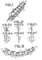
- FIG. 3 represents a front view of an embodiment of a device ensuring electrical and thermal contact between several metal surfaces which is obtained by the process according to the invention.
- the reinforcement 2 is constituted by a flexible strip, but the reinforcement shown in FIG. 3 comprises, in the direction of the length, on two opposite edges, two series of slots 8 and 9, perpendicular to the axis of the reinforcement 00 '.
- the slots of the two series 8 and 9 alternate on the frame.
- the device shown in Figure 3 can be used flat disc-shaped, the slots of one of the series, the series 8 in Figure 3, overlap, while the slots of the other series, the series 9 in Figure 3, deviate, while the device shown in Figure 1 can only be used wrapped around a cylinder or in the form of a rectangular strip.
- the means limiting the movement of the wire along the axis of the armature consist of two series of orifices, 6 and 7, drilled on the plate constituting the armature 2, lengthwise.
- the metal wire 1 is introduced into these orifices.
- FIG. 4 represents a perspective view of an embodiment of a device ensuring electrical and thermal contact between several metal surfaces which is obtained by the method according to the invention.
- the frame 2 is constituted by a sheet cut out in the form of a ring.
- Two rods 3 are arranged on either side of the frame, these rods are also in the form of a ring, they are made of plastic or in any other material which can be dissolved after winding.
- the metal wire is introduced into the concavities 13 of the corrugations.
- two metallic wires 10 and 11 are wound in a helix, in an identical manner, and alternate on the armature.
- the number of metallic wires can be any.
- FIG. 5 represents a perspective view of another embodiment of a device ensuring electrical and thermal contact between several metal surfaces which is obtained by the method according to the invention.
- the frame 2 is constituted by a wound wire, substantially helical, with contiguous turns.
- the propellers of the frame and means limiting the movement of the wire can be flattened to limit the overall width of the device.
- the metal wire 1 ensuring the electrical contact between several metal surfaces is inserted into the space between two consecutive and non-contiguous turns of the propeller 14 constituting the means limiting the movement of the wire.
- FIG. 6 represents another embodiment of a device ensuring electrical and thermal contact between several metal surfaces which is obtained by the process according to the invention.
- a metal wire 23 is wound substantially in a helix both around the frame 2, which is constituted in this example by a flexible strip, and around at least a first rod arranged parallel to the axis of the frame 00 ', this wand is not shown in the figure.
- Another metallic wire 24 is then wound, substantially in a helix, both around the frame 2 and at least one second rod arranged parallel to the axis of the frame and on the other side of the frame. compared to the first wand.
- the device obtained has more solidity and makes it possible to prevent the deformations received by the metal wire located on one side of the frame from being transmitted to the metal wire located on the other side of the frame.
- the device ensuring electrical and thermal contact obtained by the method according to the invention is used in numerous applications, in particular in the field of microwave frequencies.
- This device is thus used in microwave electronic tubes of coaxial geometry, such as power triodes and tetrodes used by radio and television transmitters, radars and industrial high frequency generators, to ensure electrical contact. and thermal between the surfaces of two coaxial cylinders constituting two connections of a tube.
- the device can then be housed in a groove hollowed out on the surface of one of the two cylinders. It can also be "fixed to the surface of one of the two cylinders, either as shown in FIG.
- This device can also be used, as shown in FIG. 9, to make an electrical contact between two walls 15 and 16 of a microwave coaxial cavity.
- the device 20 then serves as a piston. It is driven in translation, as shown by a double arrow in Figure 9, by a control rod.
- FIG. 11 is a perspective view, two devices 20, obtained by the method according to the invention, and mounted in two grooves 31 located on either side of a piston 32
- the devices 20 are connected to the piston by their armature 2. It is possible to use to accommodate the devices 20 grooves 31 of rectangular shape, or of triangular shape, as shown in FIG. 11.
- the grooves of triangular shape have the 'Advantage when the devices 20 are substantially diamond-shaped, as shown in Figure 11, to allow very good ventilation of the contacts thanks to the space between each device 20 and the piston 32.
- the devices 20 are in contact with two sides of the grooves and therefore follow the slightest displacements of the piston 32, which is not the case for the rectangular grooves with which it is difficult to make a fine adjustment of the position of the piston, because the devices 20 do not ensure good contact with the piston, especially since it is necessary to provide a clearance between the armature and the piston to leave the armature free to change dimensions.
- the piston is of course movable in translation as shown by a double arrow in FIG. 11.
- the device obtained by the method according to the invention can be used to make electrical and thermal contact between several metallic surfaces, four metallic surfaces, for example, for the substantially hexagonal device, shown seen from the front in Figure 12.
- the four surfaces A, B, C, D are based on the sides a, b, c, d, of the hexagon, these surfaces A, B, C, D, may or may not be animated with rotational movements.
- the device obtained by the method according to the invention can be housed, as shown in FIG. 13, in a helical groove 21 provided on the surface of one of the two parts between which the device 20 provides electrical and thermal contact.
- This groove 21 makes it possible to increase the surface of the contact produced by the device 20 between the two parts 18 and 19.
- the part 19 comprises cooling fins 22.
- the device 20 shown in FIG. 13 ensures contact between parts 18 and 19 which can be subjected to both rotational and translational movements.
- a current of 200 amperes is established between parts 25 and 26, which are made of brass.
- the recorded voltage drop is only 28 millivolts, whereas it would be at least 50 millivolts if the contact between the metal surfaces of parts 25 and 26 was established by devices according to the prior art.
- the temperature of the rooms 25 and 26 does not exceed 40 degrees Celcius, because the device according to the invention allows good ventilation to be easily achieved.
Landscapes
- Cooling Or The Like Of Electrical Apparatus (AREA)
- Coils Or Transformers For Communication (AREA)
- Manufacture Of Switches (AREA)
- Manufacture Of Motors, Generators (AREA)
Applications Claiming Priority (2)
| Application Number | Priority Date | Filing Date | Title |
|---|---|---|---|
| FR7902282A FR2448221A1 (fr) | 1979-01-30 | 1979-01-30 | Procede de fabrication d'un dispositif assurant un contact electrique et thermique entre plusieurs surfaces metalliques, dispositif obtenu par ce procede et application de ce dispositif |
| FR7902282 | 1979-01-30 |
Publications (2)
| Publication Number | Publication Date |
|---|---|
| EP0014128A1 true EP0014128A1 (de) | 1980-08-06 |
| EP0014128B1 EP0014128B1 (de) | 1984-03-21 |
Family
ID=9221339
Family Applications (1)
| Application Number | Title | Priority Date | Filing Date |
|---|---|---|---|
| EP80400058A Expired EP0014128B1 (de) | 1979-01-30 | 1980-01-15 | Vorrichtung zur Gewährleistung eines elektrischen und thermischen Kontaktes zwischen mehreren metallischen Oberflächen, und deren Verwendung |
Country Status (4)
| Country | Link |
|---|---|
| US (1) | US4488086A (de) |
| EP (1) | EP0014128B1 (de) |
| DE (1) | DE3067076D1 (de) |
| FR (1) | FR2448221A1 (de) |
Citations (4)
| Publication number | Priority date | Publication date | Assignee | Title |
|---|---|---|---|---|
| US2379047A (en) * | 1942-05-01 | 1945-06-26 | Bell Telephone Labor Inc | Bridging conductor |
| US2829352A (en) * | 1953-12-24 | 1958-04-01 | Varian Associates | Tunable waveguide short |
| US2932806A (en) * | 1958-12-02 | 1960-04-12 | Bomac Lab Inc | Broadband microwave window |
| US3255426A (en) * | 1964-03-09 | 1966-06-07 | Jesse L Butler | Stripline having two ground planes mechanically spaced by removable longitudinal electrical connectors disposed parallel to signal conductor |
Family Cites Families (2)
| Publication number | Priority date | Publication date | Assignee | Title |
|---|---|---|---|---|
| US3614518A (en) * | 1970-03-16 | 1971-10-19 | Varian Associates | Microwave tuner having sliding contactors |
| JPS5544404Y2 (de) * | 1974-05-09 | 1980-10-18 |
-
1979
- 1979-01-30 FR FR7902282A patent/FR2448221A1/fr active Granted
-
1980
- 1980-01-15 EP EP80400058A patent/EP0014128B1/de not_active Expired
- 1980-01-15 DE DE8080400058T patent/DE3067076D1/de not_active Expired
-
1983
- 1983-01-28 US US06/462,106 patent/US4488086A/en not_active Expired - Lifetime
Patent Citations (4)
| Publication number | Priority date | Publication date | Assignee | Title |
|---|---|---|---|---|
| US2379047A (en) * | 1942-05-01 | 1945-06-26 | Bell Telephone Labor Inc | Bridging conductor |
| US2829352A (en) * | 1953-12-24 | 1958-04-01 | Varian Associates | Tunable waveguide short |
| US2932806A (en) * | 1958-12-02 | 1960-04-12 | Bomac Lab Inc | Broadband microwave window |
| US3255426A (en) * | 1964-03-09 | 1966-06-07 | Jesse L Butler | Stripline having two ground planes mechanically spaced by removable longitudinal electrical connectors disposed parallel to signal conductor |
Also Published As
| Publication number | Publication date |
|---|---|
| FR2448221A1 (fr) | 1980-08-29 |
| US4488086A (en) | 1984-12-11 |
| DE3067076D1 (en) | 1984-04-26 |
| EP0014128B1 (de) | 1984-03-21 |
| FR2448221B1 (de) | 1982-04-30 |
Similar Documents
| Publication | Publication Date | Title |
|---|---|---|
| FR2485859A1 (fr) | Cable flexible de chauffage electrique a auto-limitation de temperature | |
| CA1111377A (fr) | Electrode pour appareil generateur d'ozone | |
| EP0021879A1 (de) | Druckempfindliche Vorrichtung mit piezoelektrischem polymerem Körper und Verfahren zu ihrer Herstellung | |
| CH630750A5 (fr) | Douille, pour dispositif de contact electrique a fiche et douille, et son procede de fabrication. | |
| CA1137284A (fr) | Procede de fabrication d'un element isolant comportant une portion centrale entouree d'une pluralite d'ailettes, et element isolant obtenu par ce procede | |
| FR2817617A1 (fr) | Procede de fabrication de convertisseurs thermo-electriques | |
| EP3935653A1 (de) | Selbstleuchtendes stromkabel mit offset-energie-rückgewinnungssystem und verfahren zur herstellung davon | |
| FR2530074A1 (fr) | Fusible cylindrique | |
| EP2115815A1 (de) | Verfahren zur herstellung eines kabels zur verbindung der pole einer batterie, installation zur umsetzung dieses verfahrens und auf diese weise hergestelltes kabel | |
| EP0014128B1 (de) | Vorrichtung zur Gewährleistung eines elektrischen und thermischen Kontaktes zwischen mehreren metallischen Oberflächen, und deren Verwendung | |
| CA2211034A1 (fr) | Dispositif et methode pour deglacer un element structural allonge | |
| FR3050488A1 (fr) | Actionneur rotatif utilisant des fils d’alliage a memoire de forme en traction | |
| FR2529007A1 (fr) | Cable electrique supportant des conditions d'emploi tres severes | |
| FR3093586A1 (fr) | Câble de puissance auto-éclairé à bas courant et gardant sa souplesse et procédé de fabrication associé | |
| KR20020050247A (ko) | 후크 정류자 | |
| FR2589620A1 (fr) | Condensateur multipiste | |
| FR2557741A1 (fr) | Contact electrique a faible force d'insertion et son procede de realisation | |
| EP1583461B1 (de) | Longitudinale orientierbare struktur | |
| FR2473778A1 (fr) | Plaquette d'electrode pour condensateur | |
| EP0209466B1 (de) | Vorrichtung zur sequentiellen mecanischen Auslösung | |
| EP1111733B1 (de) | Flexible Verbindungsanordnung | |
| FR2474239A1 (fr) | Lentilles electroniques pour canons a electrons, notamment pour tubes images de television | |
| US4161702A (en) | Distributed feedback filter and laser | |
| EP0203848B1 (de) | Verfahren zur Herstellung eines Halbleiterlasers mit Streifengeometrie und ein nach diesem Verfahren hergestellter Laser | |
| FR2691296A1 (fr) | Câble coaxial à extrémité d'âme centrée, son procédé de réalisation, et dispositif pour la mise en Óoeuvre dudit procédé. |
Legal Events
| Date | Code | Title | Description |
|---|---|---|---|
| PUAI | Public reference made under article 153(3) epc to a published international application that has entered the european phase |
Free format text: ORIGINAL CODE: 0009012 |
|
| AK | Designated contracting states |
Designated state(s): DE GB IT NL |
|
| 17P | Request for examination filed | ||
| ITF | It: translation for a ep patent filed | ||
| GRAA | (expected) grant |
Free format text: ORIGINAL CODE: 0009210 |
|
| AK | Designated contracting states |
Designated state(s): DE GB IT NL |
|
| REF | Corresponds to: |
Ref document number: 3067076 Country of ref document: DE Date of ref document: 19840426 |
|
| PLBE | No opposition filed within time limit |
Free format text: ORIGINAL CODE: 0009261 |
|
| STAA | Information on the status of an ep patent application or granted ep patent |
Free format text: STATUS: NO OPPOSITION FILED WITHIN TIME LIMIT |
|
| 26N | No opposition filed | ||
| ITTA | It: last paid annual fee | ||
| PGFP | Annual fee paid to national office [announced via postgrant information from national office to epo] |
Ref country code: NL Payment date: 19981214 Year of fee payment: 20 Ref country code: DE Payment date: 19981214 Year of fee payment: 20 |
|
| PGFP | Annual fee paid to national office [announced via postgrant information from national office to epo] |
Ref country code: GB Payment date: 19981216 Year of fee payment: 20 |
|
| PG25 | Lapsed in a contracting state [announced via postgrant information from national office to epo] |
Ref country code: GB Free format text: LAPSE BECAUSE OF EXPIRATION OF PROTECTION Effective date: 20000114 |
|
| PG25 | Lapsed in a contracting state [announced via postgrant information from national office to epo] |
Ref country code: NL Free format text: LAPSE BECAUSE OF EXPIRATION OF PROTECTION Effective date: 20000115 |
|
| REG | Reference to a national code |
Ref country code: GB Ref legal event code: PE20 Effective date: 20000114 |
|
| NLV7 | Nl: ceased due to reaching the maximum lifetime of a patent |
Effective date: 20000115 |