EP0014143A1 - Wechselgetriebe-Steuerung für Kraftfahrzeuge - Google Patents
Wechselgetriebe-Steuerung für Kraftfahrzeuge Download PDFInfo
- Publication number
- EP0014143A1 EP0014143A1 EP80400087A EP80400087A EP0014143A1 EP 0014143 A1 EP0014143 A1 EP 0014143A1 EP 80400087 A EP80400087 A EP 80400087A EP 80400087 A EP80400087 A EP 80400087A EP 0014143 A1 EP0014143 A1 EP 0014143A1
- Authority
- EP
- European Patent Office
- Prior art keywords
- passage
- control
- fluid
- clutch
- piston
- Prior art date
- Legal status (The legal status is an assumption and is not a legal conclusion. Google has not performed a legal analysis and makes no representation as to the accuracy of the status listed.)
- Granted
Links
- 230000008859 change Effects 0.000 title claims abstract description 11
- 239000012530 fluid Substances 0.000 claims abstract description 32
- 230000003247 decreasing effect Effects 0.000 claims abstract description 9
- 230000007246 mechanism Effects 0.000 claims abstract description 7
- 230000005284 excitation Effects 0.000 claims description 6
- 230000009471 action Effects 0.000 description 5
- 230000008878 coupling Effects 0.000 description 3
- 238000010168 coupling process Methods 0.000 description 3
- 238000005859 coupling reaction Methods 0.000 description 3
- 230000000694 effects Effects 0.000 description 3
- 230000004044 response Effects 0.000 description 3
- 238000006073 displacement reaction Methods 0.000 description 2
- 238000005192 partition Methods 0.000 description 2
- 230000002093 peripheral effect Effects 0.000 description 2
- 230000001052 transient effect Effects 0.000 description 2
- KRQUFUKTQHISJB-YYADALCUSA-N 2-[(E)-N-[2-(4-chlorophenoxy)propoxy]-C-propylcarbonimidoyl]-3-hydroxy-5-(thian-3-yl)cyclohex-2-en-1-one Chemical compound CCC\C(=N/OCC(C)OC1=CC=C(Cl)C=C1)C1=C(O)CC(CC1=O)C1CCCSC1 KRQUFUKTQHISJB-YYADALCUSA-N 0.000 description 1
- 241000287107 Passer Species 0.000 description 1
- 241000897276 Termes Species 0.000 description 1
- 230000001133 acceleration Effects 0.000 description 1
- 230000000881 depressing effect Effects 0.000 description 1
- 235000021183 entrée Nutrition 0.000 description 1
- 230000001681 protective effect Effects 0.000 description 1
- 230000002747 voluntary effect Effects 0.000 description 1
Images
Classifications
-
- B—PERFORMING OPERATIONS; TRANSPORTING
- B60—VEHICLES IN GENERAL
- B60W—CONJOINT CONTROL OF VEHICLE SUB-UNITS OF DIFFERENT TYPE OR DIFFERENT FUNCTION; CONTROL SYSTEMS SPECIALLY ADAPTED FOR HYBRID VEHICLES; ROAD VEHICLE DRIVE CONTROL SYSTEMS FOR PURPOSES NOT RELATED TO THE CONTROL OF A PARTICULAR SUB-UNIT
- B60W30/00—Purposes of road vehicle drive control systems not related to the control of a particular sub-unit, e.g. of systems using conjoint control of vehicle sub-units
- B60W30/18—Propelling the vehicle
-
- B—PERFORMING OPERATIONS; TRANSPORTING
- B60—VEHICLES IN GENERAL
- B60W—CONJOINT CONTROL OF VEHICLE SUB-UNITS OF DIFFERENT TYPE OR DIFFERENT FUNCTION; CONTROL SYSTEMS SPECIALLY ADAPTED FOR HYBRID VEHICLES; ROAD VEHICLE DRIVE CONTROL SYSTEMS FOR PURPOSES NOT RELATED TO THE CONTROL OF A PARTICULAR SUB-UNIT
- B60W10/00—Conjoint control of vehicle sub-units of different type or different function
- B60W10/02—Conjoint control of vehicle sub-units of different type or different function including control of driveline clutches
-
- B—PERFORMING OPERATIONS; TRANSPORTING
- B60—VEHICLES IN GENERAL
- B60W—CONJOINT CONTROL OF VEHICLE SUB-UNITS OF DIFFERENT TYPE OR DIFFERENT FUNCTION; CONTROL SYSTEMS SPECIALLY ADAPTED FOR HYBRID VEHICLES; ROAD VEHICLE DRIVE CONTROL SYSTEMS FOR PURPOSES NOT RELATED TO THE CONTROL OF A PARTICULAR SUB-UNIT
- B60W10/00—Conjoint control of vehicle sub-units of different type or different function
- B60W10/10—Conjoint control of vehicle sub-units of different type or different function including control of change-speed gearings
-
- F—MECHANICAL ENGINEERING; LIGHTING; HEATING; WEAPONS; BLASTING
- F16—ENGINEERING ELEMENTS AND UNITS; GENERAL MEASURES FOR PRODUCING AND MAINTAINING EFFECTIVE FUNCTIONING OF MACHINES OR INSTALLATIONS; THERMAL INSULATION IN GENERAL
- F16D—COUPLINGS FOR TRANSMITTING ROTATION; CLUTCHES; BRAKES
- F16D48/00—External control of clutches
- F16D48/02—Control by fluid pressure
-
- F—MECHANICAL ENGINEERING; LIGHTING; HEATING; WEAPONS; BLASTING
- F16—ENGINEERING ELEMENTS AND UNITS; GENERAL MEASURES FOR PRODUCING AND MAINTAINING EFFECTIVE FUNCTIONING OF MACHINES OR INSTALLATIONS; THERMAL INSULATION IN GENERAL
- F16H—GEARING
- F16H63/00—Control outputs from the control unit to change-speed- or reversing-gearings for conveying rotary motion or to other devices than the final output mechanism
- F16H63/40—Control outputs from the control unit to change-speed- or reversing-gearings for conveying rotary motion or to other devices than the final output mechanism comprising signals other than signals for actuating the final output mechanisms
- F16H63/46—Signals to a clutch outside the gearbox
-
- F—MECHANICAL ENGINEERING; LIGHTING; HEATING; WEAPONS; BLASTING
- F16—ENGINEERING ELEMENTS AND UNITS; GENERAL MEASURES FOR PRODUCING AND MAINTAINING EFFECTIVE FUNCTIONING OF MACHINES OR INSTALLATIONS; THERMAL INSULATION IN GENERAL
- F16D—COUPLINGS FOR TRANSMITTING ROTATION; CLUTCHES; BRAKES
- F16D48/00—External control of clutches
- F16D48/02—Control by fluid pressure
- F16D2048/0203—Control by fluid pressure with an accumulator; Details thereof
-
- F—MECHANICAL ENGINEERING; LIGHTING; HEATING; WEAPONS; BLASTING
- F16—ENGINEERING ELEMENTS AND UNITS; GENERAL MEASURES FOR PRODUCING AND MAINTAINING EFFECTIVE FUNCTIONING OF MACHINES OR INSTALLATIONS; THERMAL INSULATION IN GENERAL
- F16D—COUPLINGS FOR TRANSMITTING ROTATION; CLUTCHES; BRAKES
- F16D48/00—External control of clutches
- F16D48/02—Control by fluid pressure
- F16D2048/0227—Source of pressure producing the clutch engagement or disengagement action within a circuit; Means for initiating command action in power assisted devices
- F16D2048/0254—Double actuation, i.e. two actuation means can produce independently an engagement or disengagement of the clutch
Definitions
- the present invention relates to a speed change control for a motor vehicle, and it relates more particularly to a control of this kind comprising a first control member for shifting the increasing gears and a second control member for that of the decreasing gears, a fluid pressure cylinder for actuating the clutch, and a gearbox control mechanism including means sensitive to a fluid pressure for the passage of increasing ratios and for that of decreasing ratios.
- this speed change command comprises, in combination, a first three-way distributor allowing the active chamber of the clutch cylinder to be connected to a source of pressurized fluid either to a return tank depending on whether or not it is excited, a second four-way distributor associated with means sensitive to a fluid pressure, themselves constituted by two independent jacks, this second distributor making it possible either to connect in function of the actuator actuated one or the other of said jacks to the source of pressurized fluid through the active chamber of the clutch jack and the other jack to the return tank, or to connect in the absence of excitation the two jacks to said tank, these two distributors being simultaneously excited by one or the other of the control members and automatically de-energized by a control means responding to the end of execution of the passage of the desired ratio, and the connection through the active chamber of the clutch actuator being established only beyond a predetermined value of the stroke of its piston which corresponds to the proper execution of the clutch.
- the above-mentioned connection through the active chamber of the clutch cylinder is established, through a passage made in the piston itself, between an intake orifice of the pressurized fluid and an outlet lumen which communicates with said passage only when the piston stroke reaches said predetermined value.
- control members and the distributors are constituted respectively by push-buttons and by solenoid valves, and in such a case the control means responding to the end of execution of the passage of the desired ratio can then simply be constituted by a limit switch actuated by one or other of the gearbox control cylinders.
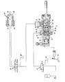
- the rapid speed change control comprises a first distributor 10, constituted in the example represented by a three-way and two-position solenoid valve, the mode of operation of which will be specified below.
- This distributor makes it possible to connect the active chamber 22 of a hydraulic cylinder 20 used for controlling the clutch (not shown) of the vehicle, either to a source of HP pressurized fluid when the control coil of this distributor is energized, either to a BP return tank when the coil is not energized (case of the position shown in the drawing).
- the control also includes a second distributor 30, constituted by a four-way and three-position solenoid valve.
- This second distributor is associated with a gearbox control mechanism, designated as a whole by the reference 40, this mechanism more precisely including two independent jacks 42 and 44, assigned respectively to the passage of increasing ratios and decreasing ratios; the structure of this mechanism is not in itself part of the invention, but it must be understood that it is designed in such a way that the pressurization of one or the other of its jacks results in a step of angular displacement in one direction or the other of an output shaft 46 which carries out the desired couplings inside the box; it follows that the passage from the first to the fourth speed, for example, requires three pressurizations and successive pressurization of the corresponding cylinder.
- the central position or rest position of the distributor 30 is used to connect the two jacks 42 and 44 to the return tank BP; for this position, the gearbox (not shown in the drawing) works on the report which was imposed on it during a previous maneuver.
- the distributor 30 connects one of the jacks 42 and 44 to an outlet orifice 31 of the jack 20 of clutch control, and the other cylinder to the BP return tank.
- the speed change control according to the invention finally comprises two control members assigned one to the passage of increasing gears and the other to that of decreasing gears.
- These control members which are not shown in the drawings, may advantageously be constituted by push buttons mounted on the steering wheel of the vehicle, this so as to allow the driver to control with a finger and without having to release the steering wheel shifting the desired gear.
- One of these push-buttons allows, when pressed, to simultaneously supply the excitation coil of the first distributor 10 and one of the excitation coils of the second distributor 30; similarly, the second push-button controls by its depressing the supply of the excitation coil of the first distributor 10 and of the other excitation coil of the second distributor 30.
- the actuator 20 for actuating the clutch comprises a hollow piston 21 delimiting, with a fixed partition 23, an active chamber 22 which communicates with an intake orifice 24 for the fluid under pressure.
- the piston 21 puts the active chamber 22 of the jack into communication with a peripheral groove 28.
- the outlet orifice 31 of the jack communicates on the other hand with a light pierced in its fixed body and extended by a longitudinal groove 29, the left end of which is normally distant from the groove 28 and is separated from it by an O-ring seal; the spacing between this end and this groove is determined in such a way that, when the piston 21 is pushed to the right under the action of the fluid under pressure, the communication between the groove and the groove is established only once accomplished a minimum value of the piston stroke corresponding to an effective disengagement of the clutch.
- the groove 29 communicates on the other hand, by means of a diametral bore 51 and an axial bore 52, with the internal cavity 26 of the piston 21; however, this communication is controlled by a one-way valve 50 which lets the pressurized fluid pass only in the direction going from the outlet orifice 31 to the cavity 26 of the piston, and consequently to the active chamber 22; on examining the drawing, it will be noted that, provided that the valve 50 is open, the auxiliary passage thus formed in the piston 21 establishes a communication which is independent of the position of the piston.
- the valve 50 essentially plays a protective role against transient overpressures which may appear downstream of the jack 20 during the execution of the maneuvers.
- the jack 20 finally comprises a second actuating piston 32, mounted in series with the piston 21 on which it bears by a push rod 33 sealingly passing through the fixed partition 23; this piston 32 is actuated only in response to a voluntary operation of the clutch pedal 34, and should normally be considered only as an emergency means.
Landscapes
- Engineering & Computer Science (AREA)
- Mechanical Engineering (AREA)
- General Engineering & Computer Science (AREA)
- Transportation (AREA)
- Chemical & Material Sciences (AREA)
- Combustion & Propulsion (AREA)
- Automation & Control Theory (AREA)
- Physics & Mathematics (AREA)
- Fluid Mechanics (AREA)
- Hydraulic Clutches, Magnetic Clutches, Fluid Clutches, And Fluid Joints (AREA)
Applications Claiming Priority (2)
| Application Number | Priority Date | Filing Date | Title |
|---|---|---|---|
| IT19520/79A IT1110714B (it) | 1979-01-23 | 1979-01-23 | Comando di cambio di velcita' per veicolo automobile |
| IT1952079 | 1979-01-23 |
Publications (2)
| Publication Number | Publication Date |
|---|---|
| EP0014143A1 true EP0014143A1 (de) | 1980-08-06 |
| EP0014143B1 EP0014143B1 (de) | 1982-09-01 |
Family
ID=11158721
Family Applications (1)
| Application Number | Title | Priority Date | Filing Date |
|---|---|---|---|
| EP80400087A Expired EP0014143B1 (de) | 1979-01-23 | 1980-01-21 | Wechselgetriebe-Steuerung für Kraftfahrzeuge |
Country Status (3)
| Country | Link |
|---|---|
| EP (1) | EP0014143B1 (de) |
| DE (1) | DE3060784D1 (de) |
| IT (1) | IT1110714B (de) |
Cited By (4)
| Publication number | Priority date | Publication date | Assignee | Title |
|---|---|---|---|---|
| DE3217662A1 (de) * | 1982-05-11 | 1983-11-24 | Emil Weber Fabrik für Ölhydraulik GmbH & Co, 7129 Güglingen | Hydraulische betaetigungsvorrichtung fuer die kupplung von kraftfahrzeugen |
| EP0129632A1 (de) * | 1983-06-23 | 1985-01-02 | BENDIX ITALIA S.p.A. | Hydraulische Betätigungsvorrichtung eines Steuerelements, insbesondere einer Gangschaltung |
| FR2612464A1 (fr) * | 1987-03-20 | 1988-09-23 | Knorr Bremse Ag | Servo-commande hydraulique pour embrayage a assistance pneumatique |
| EP3098471A1 (de) * | 2015-05-28 | 2016-11-30 | Raicam Clutch Limited | Fahrzeugantriebswellenkupplungssteuerungssysteme |
Families Citing this family (1)
| Publication number | Priority date | Publication date | Assignee | Title |
|---|---|---|---|---|
| DE102014102880B4 (de) * | 2014-03-05 | 2015-10-08 | Knorr-Bremse Systeme für Nutzfahrzeuge GmbH | Kupplungskraftverstärker mit im Bereich der Kolbenstange angeordneten speziellen dynamischen Dichtungsmitteln |
Citations (5)
| Publication number | Priority date | Publication date | Assignee | Title |
|---|---|---|---|---|
| DE1163164B (de) * | 1955-02-15 | 1964-02-13 | Citroen Sa | Hydraulische Steuervorrichtung fuer den Gangwechsel in Geschwindigkeitswechselgetrieben von Kraftfahrzeugen |
| DE1224620B (de) * | 1954-10-28 | 1966-09-08 | Daimler Benz Ag | Getriebeschalteinrichtung fuer Kraftfahrzeuge, insbesondere fuer Renn- und Sportwagen |
| US3433101A (en) * | 1966-01-27 | 1969-03-18 | Bosch Gmbh Robert | Electronic arrangement for shifting gears in motor vehicles |
| US3530668A (en) * | 1968-03-30 | 1970-09-29 | Gunter Siebers | Rapid gear-change apparatus |
| FR2078997A5 (de) * | 1970-02-28 | 1971-11-05 | Cav Ltd |
-
1979
- 1979-01-23 IT IT19520/79A patent/IT1110714B/it active
-
1980
- 1980-01-21 DE DE8080400087T patent/DE3060784D1/de not_active Expired
- 1980-01-21 EP EP80400087A patent/EP0014143B1/de not_active Expired
Patent Citations (5)
| Publication number | Priority date | Publication date | Assignee | Title |
|---|---|---|---|---|
| DE1224620B (de) * | 1954-10-28 | 1966-09-08 | Daimler Benz Ag | Getriebeschalteinrichtung fuer Kraftfahrzeuge, insbesondere fuer Renn- und Sportwagen |
| DE1163164B (de) * | 1955-02-15 | 1964-02-13 | Citroen Sa | Hydraulische Steuervorrichtung fuer den Gangwechsel in Geschwindigkeitswechselgetrieben von Kraftfahrzeugen |
| US3433101A (en) * | 1966-01-27 | 1969-03-18 | Bosch Gmbh Robert | Electronic arrangement for shifting gears in motor vehicles |
| US3530668A (en) * | 1968-03-30 | 1970-09-29 | Gunter Siebers | Rapid gear-change apparatus |
| FR2078997A5 (de) * | 1970-02-28 | 1971-11-05 | Cav Ltd |
Cited By (4)
| Publication number | Priority date | Publication date | Assignee | Title |
|---|---|---|---|---|
| DE3217662A1 (de) * | 1982-05-11 | 1983-11-24 | Emil Weber Fabrik für Ölhydraulik GmbH & Co, 7129 Güglingen | Hydraulische betaetigungsvorrichtung fuer die kupplung von kraftfahrzeugen |
| EP0129632A1 (de) * | 1983-06-23 | 1985-01-02 | BENDIX ITALIA S.p.A. | Hydraulische Betätigungsvorrichtung eines Steuerelements, insbesondere einer Gangschaltung |
| FR2612464A1 (fr) * | 1987-03-20 | 1988-09-23 | Knorr Bremse Ag | Servo-commande hydraulique pour embrayage a assistance pneumatique |
| EP3098471A1 (de) * | 2015-05-28 | 2016-11-30 | Raicam Clutch Limited | Fahrzeugantriebswellenkupplungssteuerungssysteme |
Also Published As
| Publication number | Publication date |
|---|---|
| IT7919520A0 (it) | 1979-01-23 |
| IT1110714B (it) | 1986-01-06 |
| DE3060784D1 (en) | 1982-10-28 |
| EP0014143B1 (de) | 1982-09-01 |
Similar Documents
| Publication | Publication Date | Title |
|---|---|---|
| EP1042148B1 (de) | Hauptzylinder und wegsimulator anordnung für elektrohydraulische kraftfahrzeugbremsanlage | |
| FR2573708A1 (fr) | Dispositif d'aide au demarrage en cote pour vehicule a moteur | |
| FR2816894A1 (fr) | Systeme d'actionnement hydraulique | |
| FR2570036A1 (fr) | Dispositif de secours pour un systeme de commande electronique de transmission automatique | |
| FR2820694A1 (fr) | Systeme d'actionnement hydraulique | |
| FR2818944A1 (fr) | Installation de freinage hydraulique pour vehicule comportant un simulateur actif | |
| FR2670733A1 (fr) | Mecanisme de transmission d'une force de reaction pour servo-frein. | |
| WO2017149245A1 (fr) | Système de freinage ferroviaire pour véhicule ferroviaire et procédé de freinage d'un véhicule ferroviaire comportant un tel système | |
| EP0014143B1 (de) | Wechselgetriebe-Steuerung für Kraftfahrzeuge | |
| FR2576261A1 (fr) | Generateur de pression de freinage pour vehicule automobile | |
| FR2678869A1 (fr) | Vehicule utilitaire a quatre roues motrices. | |
| FR2880854A1 (fr) | Dispositif de soupape de frein | |
| FR2500391A1 (fr) | Installations d'antiderapage pour freins de vehicules | |
| FR2642016A1 (fr) | Commande de changement de vitesses pour vehicule automobile notamment tracteurs agricoles | |
| FR2515124A1 (fr) | Systeme de freinage pour vehicule | |
| FR2878804A1 (fr) | Assemblage de vanne pour des freins anti-patinage d'un avion | |
| FR2752210A1 (fr) | Dispositif de freinage assiste a reaction hydraulique et securite accrue | |
| FR2828662A1 (fr) | Systemes de commande hydrauliques | |
| FR2747171A1 (fr) | Actionnneur electrohydraulique pour la commande d'une boite de vitesses de vehicule du type a barillet d'entree | |
| FR2556291A1 (fr) | Installation de commande a distance d'une boite de vitesses, du type mecanique | |
| EP0642433B1 (de) | Bremsvorrichtung mit einem einzigen steuerventil für blokierschutz-und antriebsschlupfregelung | |
| FR2804194A1 (fr) | Mecanisme d'enclenchement de rapport | |
| FR2805876A1 (fr) | Systeme de manoeuvre hydraulique | |
| EP1564098B1 (de) | Bremssystem mit Geberzylinder und Unterdruckkraftverstärker | |
| FR2712540A1 (fr) | Dispositif d'assistance au débrayage dans les véhicules automobiles. |
Legal Events
| Date | Code | Title | Description |
|---|---|---|---|
| PUAI | Public reference made under article 153(3) epc to a published international application that has entered the european phase |
Free format text: ORIGINAL CODE: 0009012 |
|
| AK | Designated contracting states |
Designated state(s): CH DE FR GB NL SE |
|
| 17P | Request for examination filed |
Effective date: 19801124 |
|
| GRAA | (expected) grant |
Free format text: ORIGINAL CODE: 0009210 |
|
| AK | Designated contracting states |
Designated state(s): CH DE FR GB NL SE |
|
| REF | Corresponds to: |
Ref document number: 3060784 Country of ref document: DE Date of ref document: 19821028 |
|
| PGFP | Annual fee paid to national office [announced via postgrant information from national office to epo] |
Ref country code: CH Payment date: 19950113 Year of fee payment: 16 |
|
| PGFP | Annual fee paid to national office [announced via postgrant information from national office to epo] |
Ref country code: SE Payment date: 19950118 Year of fee payment: 16 |
|
| EAL | Se: european patent in force in sweden |
Ref document number: 80400087.5 |
|
| PGFP | Annual fee paid to national office [announced via postgrant information from national office to epo] |
Ref country code: NL Payment date: 19950131 Year of fee payment: 16 |
|
| PG25 | Lapsed in a contracting state [announced via postgrant information from national office to epo] |
Ref country code: SE Effective date: 19960122 |
|
| PG25 | Lapsed in a contracting state [announced via postgrant information from national office to epo] |
Ref country code: CH Effective date: 19960131 |
|
| PG25 | Lapsed in a contracting state [announced via postgrant information from national office to epo] |
Ref country code: NL Effective date: 19960801 |
|
| REG | Reference to a national code |
Ref country code: CH Ref legal event code: PL |
|
| NLV4 | Nl: lapsed or anulled due to non-payment of the annual fee |
Effective date: 19960801 |
|
| EUG | Se: european patent has lapsed |
Ref document number: 80400087.5 |
|
| PGFP | Annual fee paid to national office [announced via postgrant information from national office to epo] |
Ref country code: GB Payment date: 19990113 Year of fee payment: 20 |
|
| PGFP | Annual fee paid to national office [announced via postgrant information from national office to epo] |
Ref country code: FR Payment date: 19990114 Year of fee payment: 20 |
|
| PGFP | Annual fee paid to national office [announced via postgrant information from national office to epo] |
Ref country code: DE Payment date: 19990330 Year of fee payment: 20 |
|
| PG25 | Lapsed in a contracting state [announced via postgrant information from national office to epo] |
Ref country code: GB Free format text: LAPSE BECAUSE OF EXPIRATION OF PROTECTION Effective date: 20000120 |
|
| REG | Reference to a national code |
Ref country code: GB Ref legal event code: PE20 Effective date: 20000120 |
|
| PLBE | No opposition filed within time limit |
Free format text: ORIGINAL CODE: 0009261 |
|
| STAA | Information on the status of an ep patent application or granted ep patent |
Free format text: STATUS: NO OPPOSITION FILED WITHIN TIME LIMIT |