EP0014270A2 - Procédé et dispositif pour le taillage des flancs de la partie coupante d'un outil trempé - Google Patents
Procédé et dispositif pour le taillage des flancs de la partie coupante d'un outil trempé Download PDFInfo
- Publication number
- EP0014270A2 EP0014270A2 EP79200744A EP79200744A EP0014270A2 EP 0014270 A2 EP0014270 A2 EP 0014270A2 EP 79200744 A EP79200744 A EP 79200744A EP 79200744 A EP79200744 A EP 79200744A EP 0014270 A2 EP0014270 A2 EP 0014270A2
- Authority
- EP
- European Patent Office
- Prior art keywords
- knife
- cutting
- steel
- wheel
- knife steel
- Prior art date
- Legal status (The legal status is an assumption and is not a legal conclusion. Google has not performed a legal analysis and makes no representation as to the accuracy of the status listed.)
- Granted
Links
Images


Classifications
-
- B—PERFORMING OPERATIONS; TRANSPORTING
- B24—GRINDING; POLISHING
- B24B—MACHINES, DEVICES, OR PROCESSES FOR GRINDING OR POLISHING; DRESSING OR CONDITIONING OF ABRADING SURFACES; FEEDING OF GRINDING, POLISHING, OR LAPPING AGENTS
- B24B3/00—Sharpening cutting edges, e.g. of tools; Accessories therefor, e.g. for holding the tools
- B24B3/34—Sharpening cutting edges, e.g. of tools; Accessories therefor, e.g. for holding the tools of turning or planing tools or tool bits, e.g. gear cutters
Definitions
- the invention relates to a method for generating surfaces of a cutting head on a hardened knife steel for use in a knife head of a gear cutting machine, and a device for carrying out the method.
- a knife steel which is suitable for use in a knife head of a gear cutting machine, originally usually has a rod-like shape with a square cross section.
- This knife steel must be provided with a cutting head at one end before it is inserted into the knife head.
- the cutting head is formed by a plurality of surfaces, more or less inclined against the knife steel axis, two of these surfaces meeting in a common cutting edge, the cutting edge.
- the usual procedure is to insert several knife steels into a machine, as is known, for example, from Swiss Patent No. 450 949.
- a machine as is known, for example, from Swiss Patent No. 450 949.
- the same surfaces of the cutting heads of the individual knives are ground simultaneously. This is done in such a way that the grinding wheel gradually by fractions a millimeter against the knife.
- the part of the knife steels to be removed is ground in layers until the desired area of the cutting heads is exposed.
- FIG. 1 shows a knife steel 5 which has a cutting head 53 at one end.
- a rake face 55 this includes, for example, a free face 54 and a further free face 54 ′ opposite the free face 54 and not visible here.
- Flank surface 54 and rake surface 55 together form a cutting edge 56.
- Both flank surfaces 54, 54 ′ and the rake surface 55 are inclined in this example against a knife steel shaft 57.
- the dashed lines indicate an original rod shape 62 of the knife steel 5.
- a preliminary profile 61 of the cutting head 53 is shown in dash-dot lines. It also includes free surfaces 63, 63 'and a rake surface 64.
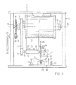
- a separating device 1 consists of a frame 2, a motor 3 suspended thereon in a manner known per se, and a holding device 4 for a knife steel 5.
- a wheel 7 is arranged on a drive shaft 6 of the motor 3, which wheel has a toothed belt 8 drives another wheel 9.
- This is, together with a cutting tool 10 - for example a cutting wheel 65 - attached to a shaft 11 which is rotatably mounted in a bearing part 12 and is secured against axial displacement.
- the bearing part 12 is with
- This bracket 15 is rotatable and coaxially pivoted with an axis 16 of the motor 3 via bolts 17 in the frame 2.
- a gear 18 is mounted on the bolt 17 between the frame 2 and the bracket 15 and firmly connected to the latter. This is in engagement with another gear 19 with a much smaller diameter.
- This is attached to a shaft 20 which is mounted in the frame 2.
- the shaft 20 is connected to a lever 21, at the end of which a handle 22 is provided.
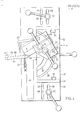
- the holding device 4 shows the holding device 4, seen from above, which is arranged displaceably on a base plate 25 ', which is not shown in detail here, but can be seen in FIG. 2.
- the holding device 4 is also assigned a base plate 26 into which slots 27 for a guide pin 28 and slots 29 for clamping levers 30 are provided.
- a base 31 is fixedly connected to the base plate 26. This base has an arcuate depression 33 for receiving a cradle 32, as can be seen from FIG. 2.
- a knife steel holder 34 is placed on the cradle 32.
- a T-shaped groove 35 is cut into the cradle 32 from below, as can also be seen from FIG. 5.
- a sliding block 36 is arranged therein.
- One here not shown in detail thread of the clamping lever 37 projects into the slider 36 such that by tightening the K lemün- lever 37, the cradle 32 is in the desired position ehal- g th.
- the cradle 32 has a groove 38 and a T-shaped groove 39.
- Two pins 40 engage in the groove 38 for guiding the knife steel holder 34.
- a sliding block is arranged in a manner not shown, which cooperates in a known manner with a further clamping lever 41 so that the knife steel holder 34 can be held on the cradle 32.
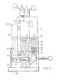
- the knife steel 5 can be inserted into a recess 42 (FIG. 5) in the knife steel holder 34.
- the knife steel 5 can be clamped in the knife steel holder 34 in a known manner with a plate 43 and a further clamping lever 44. As shown in FIG. 5, a tilt stop 45 is fastened on a shaft 46.
- This is rotatably mounted in the base 31 and secured against axial displacement by means of disc springs 47 and ring 48.
- a spring 49 is provided between a bolt 50 arranged on the tilting stop 45 and the base plate 26.
- a screw 51 anchors this to the base plate 26.
- a stop 52 is provided on one side of the tilt stop 45. 4 shows the tilting stop 45 in the elegant position from g .
- the surface 63 of the preliminary section 61 of the cutting head 53 is a rod-shaped knife steel 5
- inserted 62 in the cutter tool holder 34 of the holding device 4 of the separator 1 is positioned with a movable stopper 67 in the longitudinal direction and with the K lemm- lever 44 tightened.
- 32 scales can be applied to both a side surface 58 and a surface 59 of the cradle. Markings are accordingly on the base 31 and on the knife steel holder 34 to be provided. Scales and markings are not shown in detail in this exemplary embodiment.
- the clamping levers 37 and 41 are also tightened. Subsequently, the lateral distance of the holding device 4 from the cutting wheel 65 remains to be adjusted and to be fixed to the base plate 25 by means of the clamping levers 30.
- the motor 3 is now running - this drives the cutting wheel 65 via shaft 6, wheel 7, toothed belt 8, wheel 9 and shaft 11 - the lever 21 is pressed against the handle 22, as can be seen in FIG. 3.
- This movement is transmitted via the gears 18, 19 to the bracket 15, which thus pivots against the holding device 4.
- the gear wheels 18, 19 are designed such that the force which is introduced into the cutting device 1 on the handle 22 is amplified and now presses the cutting wheel 65 (shown in broken lines in FIG. 3) against the knife steel 5.
- a stop not shown here, limits the movement of the cutting wheel 65 against the holding device 4.
- the knife steel 5 is removed from the holding device 4 and re-clamped to produce the other surfaces 63 ', 64. If the preliminary profile 61 of the cutting head 53 is generated, then in.
- the rake and flank surfaces 64, 63, 63 ' reground to rake and flank surfaces 55, 54, 54', which in turn is not shown here.
- the grinding wheel 65 so (F ig. 4), that one side 60 of the cutting wheel 65 does not unnecessarily contact with the already formed part of the surface and thus heated.
- the bearing part 12 can be rotated around the pin 24 when the screws 13 are loosened.
- the cutting wheel 65 comes into the position indicated in FIG. 4 and the side 60 forms an angle ⁇ with the section of the plane of movement of the cutting wheel 65 represented by the straight line 6-6.
- the same effect can also be achieved, for example, with a cut-off wheel 65 which tapers towards its center and is not shown here.
- a further embodiment of the method according to the invention now consists in that a knife model 5a is used to adjust the holding device 4.
- the side face of the tilting stop 45 facing the knife steel 5 should come to rest in the plane of movement of the separating tool 10 in its position according to FIG. 5. Otherwise, loosen the clamping lever 30 and move the base plate 26 accordingly.
- the tilting stop 45 (FIG. 5) is folded up, the cradle 32 and knife steel holder 34 are now set against one another such that, for example, the free surface 63 of the knife model 5a lies against the tilting stop 45.
- To separate the tilt stop 45 is now tilted down (Fig. 4) and the knife model 5a is replaced by a knife steel 5.
- the position of the knife steel 5 along its axis in the knife steel holder 34 can be set, for example, for knife model 5a and knife steel 5 after the stop 67.
- a further embodiment of the method according to the invention is that the knife model 5a, which serves as a model for a whole series of knives, is produced from an easily machinable material on a knife grinding machine known per se.
Landscapes
- Engineering & Computer Science (AREA)
- Mechanical Engineering (AREA)
- Finish Polishing, Edge Sharpening, And Grinding By Specific Grinding Devices (AREA)
Applications Claiming Priority (2)
| Application Number | Priority Date | Filing Date | Title |
|---|---|---|---|
| CH152/79 | 1974-01-09 | ||
| CH15279 | 1979-01-09 |
Publications (3)
| Publication Number | Publication Date |
|---|---|
| EP0014270A2 true EP0014270A2 (fr) | 1980-08-20 |
| EP0014270A3 EP0014270A3 (en) | 1980-09-03 |
| EP0014270B1 EP0014270B1 (fr) | 1982-10-13 |
Family
ID=4180430
Family Applications (1)
| Application Number | Title | Priority Date | Filing Date |
|---|---|---|---|
| EP79200744A Expired EP0014270B1 (fr) | 1979-01-09 | 1979-12-10 | Procédé et dispositif pour le taillage des flancs de la partie coupante d'un outil trempé |
Country Status (4)
| Country | Link |
|---|---|
| US (1) | US4348839A (fr) |
| EP (1) | EP0014270B1 (fr) |
| JP (1) | JPS5596239A (fr) |
| DE (1) | DE2963859D1 (fr) |
Families Citing this family (3)
| Publication number | Priority date | Publication date | Assignee | Title |
|---|---|---|---|---|
| EP0076526B1 (fr) * | 1981-09-30 | 1985-02-06 | Werkzeugmaschinenfabrik Oerlikon-Bührle AG | Dispositif de coupage |
| US7468407B2 (en) * | 2005-09-26 | 2008-12-23 | National Starch And Chemical Investment Holding Copporation | Metal salts of quinolinols and quinolinol derivatives in curable compositions |
| JP7619285B2 (ja) * | 2022-01-11 | 2025-01-22 | トヨタ自動車株式会社 | 切断加工方法 |
Family Cites Families (12)
| Publication number | Priority date | Publication date | Assignee | Title |
|---|---|---|---|---|
| US1733687A (en) * | 1927-06-18 | 1929-10-29 | George H Klippel | Gauge for disk grinders |
| US1981445A (en) * | 1932-01-18 | 1934-11-20 | Eastern Cutter Salvage Corp | Cutter salvage machine |
| US2367521A (en) * | 1943-06-30 | 1945-01-16 | George J Pero | Metal-cutting machine |
| US2396904A (en) * | 1943-09-30 | 1946-03-19 | George W Booth | Apparatus for forming cutting edges on cutting tools |
| US2612082A (en) * | 1948-03-31 | 1952-09-30 | Thompson Prod Inc | Impeller blade support fixture |
| US2626491A (en) * | 1950-11-10 | 1953-01-27 | Penkoff Theodore | Fixture for grinding thread cutting tools and the like |
| US2648173A (en) * | 1952-03-07 | 1953-08-11 | William Flett | Apparatus for finishing hardened surfaces on frames for power saws |
| GB1090430A (en) * | 1964-12-24 | 1967-11-08 | Gleason Works | Gear cutting tools and method of sharpening same |
| JPS497591U (fr) * | 1972-04-24 | 1974-01-22 | ||
| SE382579B (sv) * | 1974-01-30 | 1976-02-09 | Skf Ind Trading & Dev | Sett att framstella skerverktyg av vendskertyp med flera skereggar |
| DE2409898C3 (de) * | 1974-03-01 | 1979-03-22 | Institut Sverchtvjordych Materialov Akademii Nauk Ukrainskoj Ssr, Kiew | Maschine zum Bearbeiten von hartmetallbestückten Schneidstählen |
| JPS51111289U (fr) * | 1975-03-06 | 1976-09-08 |
-
1979
- 1979-12-10 DE DE7979200744T patent/DE2963859D1/de not_active Expired
- 1979-12-10 EP EP79200744A patent/EP0014270B1/fr not_active Expired
- 1979-12-26 US US06/107,133 patent/US4348839A/en not_active Expired - Lifetime
-
1980
- 1980-01-09 JP JP61880A patent/JPS5596239A/ja active Granted
Also Published As
| Publication number | Publication date |
|---|---|
| JPH0132033B2 (fr) | 1989-06-29 |
| JPS5596239A (en) | 1980-07-22 |
| DE2963859D1 (en) | 1982-11-18 |
| EP0014270B1 (fr) | 1982-10-13 |
| US4348839A (en) | 1982-09-14 |
| EP0014270A3 (en) | 1980-09-03 |
Similar Documents
| Publication | Publication Date | Title |
|---|---|---|
| DE1577451C3 (de) | Verfahren zum Nachschleifen eines Werkzeugstahles | |
| DE2250265C3 (de) | Handwerkzeug zum Entgraten und Schaben | |
| EP0085176A1 (fr) | Tête porte-lame pour machine à tailler les roues dentées | |
| EP0189095A1 (fr) | Dispositif pour l'incision de pièces à usiner | |
| DE2428426A1 (de) | Verfahren zum schleifen von schneidwerkzeugen, die versenkt arbeiten und wenigstens eine schneidlippe haben, die durch die mitte geht, sowie vorrichtung zur durchfuehrung des verfahrens | |
| DE825943C (de) | Messerkopf und Verfahren zu seiner Ausrichtung und zur Ausrichtung der Messer | |
| DE3685864T2 (de) | Einspannvorrichtung zum schleifen von messern. | |
| DE2637078C3 (de) | Verfahren und Vorrichtung zur Bearbeitung des Fußes von gestanzten Strick- oder Wirkmaschinennadeln bzw. von Platinen, Nadelschiebern, Stößern o.dgl. | |
| EP0014270B1 (fr) | Procédé et dispositif pour le taillage des flancs de la partie coupante d'un outil trempé | |
| DE1652220C3 (de) | Verfahren zum spanabhebenden Bearbeiten eines Werkstücks | |
| DE927783C (de) | Drehmeissel mit als Profilschneide ausgebildeter Schneidkante und im wesentlichen tangential zum Werkstuecksumfang angeordnetem Meisselschaft | |
| DE2037241B2 (de) | Fraeser | |
| DE1552438C3 (de) | Einstechwerkzeughalter für Drehmaschinen | |
| DE325127C (de) | Schaerfvorrichtung mit mehreren Einsaetzen verschiedenartiger Schleifwirkung (grob und fein), insonderheit zum Schaerfen und Abziehen der Messer an landwirtschaftlichen Maschinen | |
| DE2264600C3 (de) | Vorrichtung zum Einsetzen von Zerspanungsmessern in eine Messerwelle | |
| DE1752498A1 (de) | Fraeser | |
| DE2517792C3 (de) | Vorrichtung zum Herstellen von Zahnstochern im wesentlichen dreieckigen Querschnitts aus Holzklötzen | |
| DE379059C (de) | Feststehendes oder umlaufendes Werkzeug | |
| DE709015C (de) | Verfahren und Maschine zum Herstellen von Lochungen in Papierblaettern | |
| DE2100510A1 (de) | Verfahren und Vorrichtung zur Her stellung eines Stanzmessers | |
| DE3706863A1 (de) | Verfahren und vorrichtung zur herstellung von normgerechten kerbschlagbiege-, biege- oder zugproben | |
| CH685334A5 (de) | Einstellehre für die Messer einer Dreimesserschneidemaschine. | |
| DE1627400A1 (de) | Vorrichtung zum Entgraten von Schraubenkoepfen | |
| DE1746771U (de) | Messerkopf fuer maschinen. | |
| DE2444965A1 (de) | Maschine zum nachschleifen der kreisbogenfoermigen schneiden von auswechselbaren messern von cuttern zum zerkleinern von fleisch |
Legal Events
| Date | Code | Title | Description |
|---|---|---|---|
| PUAI | Public reference made under article 153(3) epc to a published international application that has entered the european phase |
Free format text: ORIGINAL CODE: 0009012 |
|
| PUAL | Search report despatched |
Free format text: ORIGINAL CODE: 0009013 |
|
| AK | Designated contracting states |
Designated state(s): CH DE FR GB IT SE |
|
| AK | Designated contracting states |
Designated state(s): CH DE FR GB IT SE |
|
| 17P | Request for examination filed |
Effective date: 19801206 |
|
| ITF | It: translation for a ep patent filed | ||
| GRAA | (expected) grant |
Free format text: ORIGINAL CODE: 0009210 |
|
| AK | Designated contracting states |
Designated state(s): CH DE FR GB IT SE |
|
| REF | Corresponds to: |
Ref document number: 2963859 Country of ref document: DE Date of ref document: 19821118 |
|
| PGFP | Annual fee paid to national office [announced via postgrant information from national office to epo] |
Ref country code: CH Payment date: 19841119 Year of fee payment: 6 |
|
| PG25 | Lapsed in a contracting state [announced via postgrant information from national office to epo] |
Ref country code: CH Effective date: 19871231 |
|
| REG | Reference to a national code |
Ref country code: CH Ref legal event code: PL |
|
| PGFP | Annual fee paid to national office [announced via postgrant information from national office to epo] |
Ref country code: FR Payment date: 19891108 Year of fee payment: 11 |
|
| PGFP | Annual fee paid to national office [announced via postgrant information from national office to epo] |
Ref country code: SE Payment date: 19891115 Year of fee payment: 11 |
|
| ITTA | It: last paid annual fee | ||
| PG25 | Lapsed in a contracting state [announced via postgrant information from national office to epo] |
Ref country code: SE Effective date: 19901201 |
|
| PG25 | Lapsed in a contracting state [announced via postgrant information from national office to epo] |
Ref country code: FR Effective date: 19910830 |
|
| REG | Reference to a national code |
Ref country code: FR Ref legal event code: ST |
|
| PGFP | Annual fee paid to national office [announced via postgrant information from national office to epo] |
Ref country code: GB Payment date: 19911114 Year of fee payment: 13 |
|
| PGFP | Annual fee paid to national office [announced via postgrant information from national office to epo] |
Ref country code: DE Payment date: 19911121 Year of fee payment: 13 |
|
| PG25 | Lapsed in a contracting state [announced via postgrant information from national office to epo] |
Ref country code: GB Effective date: 19921210 |
|
| GBPC | Gb: european patent ceased through non-payment of renewal fee |
Effective date: 19921210 |
|
| PG25 | Lapsed in a contracting state [announced via postgrant information from national office to epo] |
Ref country code: DE Effective date: 19930901 |
|
| EUG | Se: european patent has lapsed |
Ref document number: 79200744.5 Effective date: 19910910 |
|
| PLBE | No opposition filed within time limit |
Free format text: ORIGINAL CODE: 0009261 |
|
| STAA | Information on the status of an ep patent application or granted ep patent |
Free format text: STATUS: NO OPPOSITION FILED WITHIN TIME LIMIT |