EP0014320A1 - Dispositif de rattrapage d'usure pour un frein à disque à garniture partielle - Google Patents
Dispositif de rattrapage d'usure pour un frein à disque à garniture partielle Download PDFInfo
- Publication number
- EP0014320A1 EP0014320A1 EP80100080A EP80100080A EP0014320A1 EP 0014320 A1 EP0014320 A1 EP 0014320A1 EP 80100080 A EP80100080 A EP 80100080A EP 80100080 A EP80100080 A EP 80100080A EP 0014320 A1 EP0014320 A1 EP 0014320A1
- Authority
- EP
- European Patent Office
- Prior art keywords
- brake
- adjusting
- adjustment
- bolt
- brake shoe
- Prior art date
- Legal status (The legal status is an assumption and is not a legal conclusion. Google has not performed a legal analysis and makes no representation as to the accuracy of the status listed.)
- Granted
Links
- 230000006835 compression Effects 0.000 description 3
- 238000007906 compression Methods 0.000 description 3
- 238000010276 construction Methods 0.000 description 2
- 102000004315 Forkhead Transcription Factors Human genes 0.000 description 1
- 108090000852 Forkhead Transcription Factors Proteins 0.000 description 1
- 230000000694 effects Effects 0.000 description 1
- 230000000630 rising effect Effects 0.000 description 1
Images

Classifications
-
- F—MECHANICAL ENGINEERING; LIGHTING; HEATING; WEAPONS; BLASTING
- F16—ENGINEERING ELEMENTS AND UNITS; GENERAL MEASURES FOR PRODUCING AND MAINTAINING EFFECTIVE FUNCTIONING OF MACHINES OR INSTALLATIONS; THERMAL INSULATION IN GENERAL
- F16D—COUPLINGS FOR TRANSMITTING ROTATION; CLUTCHES; BRAKES
- F16D65/00—Parts or details
- F16D65/38—Slack adjusters
- F16D65/40—Slack adjusters mechanical
- F16D65/52—Slack adjusters mechanical self-acting in one direction for adjusting excessive play
- F16D65/58—Slack adjusters mechanical self-acting in one direction for adjusting excessive play with eccentric or helical body
-
- F—MECHANICAL ENGINEERING; LIGHTING; HEATING; WEAPONS; BLASTING
- F16—ENGINEERING ELEMENTS AND UNITS; GENERAL MEASURES FOR PRODUCING AND MAINTAINING EFFECTIVE FUNCTIONING OF MACHINES OR INSTALLATIONS; THERMAL INSULATION IN GENERAL
- F16D—COUPLINGS FOR TRANSMITTING ROTATION; CLUTCHES; BRAKES
- F16D2121/00—Type of actuator operation force
- F16D2121/02—Fluid pressure
-
- F—MECHANICAL ENGINEERING; LIGHTING; HEATING; WEAPONS; BLASTING
- F16—ENGINEERING ELEMENTS AND UNITS; GENERAL MEASURES FOR PRODUCING AND MAINTAINING EFFECTIVE FUNCTIONING OF MACHINES OR INSTALLATIONS; THERMAL INSULATION IN GENERAL
- F16D—COUPLINGS FOR TRANSMITTING ROTATION; CLUTCHES; BRAKES
- F16D2125/00—Components of actuators
- F16D2125/18—Mechanical mechanisms
- F16D2125/58—Mechanical mechanisms transmitting linear movement
- F16D2125/64—Levers
Definitions
- the invention relates to an adjusting device for a partial-pad disc brake for motor vehicles or trailers, the brake shoes of which are articulated on the axle body and on both sides of a brake disc are arranged on tie rods, each of which interacts with a brake lever which can be pivoted about an axis running parallel to the outer brake shoe and which actuates a cam the outer brake shoe.
- each brake lever can be equipped with an adjusting device consisting of a worm and a worm wheel, which, however, does not automatically compensate for brake pad wear, but must be readjusted by hand.
- DE-AS 1 164 854 discloses a partial-pad disc brake with brake shoes articulated like pliers, which have a loading outside the brake disc Actuating rod can be braced against each other, which consists of two parts connected by a thread to allow readjustment to compensate for the wear of the brake pads. In this case, the brake lining wear can only be compensated by hand.
- the object of the invention is to create an automatic readjustment device of the type described at the outset, which continuously compensates for brake pad wear with an adjustable clearance and has a simple construction.
- axially adjustable adjusting bolts and rotatable adjusting bodies are arranged between the cam of each brake lever and the outer brake shoe, which cooperate via inclined surfaces, in that a prestressed spiral spring is arranged between each adjusting body and the outer brake shoe, the ends of which on the adjusting body or are fastened to the outer brake shoe, and that the starting position between the adjusting bolt and the adjusting bodies can be adjusted with an axially adjustable bolt which is arranged between the brake shoes and lies against the brake levers.
- the adjusting bolt, the adjusting body and the spiral spring can be arranged in a bore in the outer brake shoe, which is covered with a cover.
- the spiral spring is expediently arranged in a recess in the bottom of the adjusting body, into which a on the outer brake cheek attached fastening bolt protrudes.
- An adjusting device designed according to the invention has the advantage that it has a continuously operating, automatic adjusting device to compensate for brake pad wear, and at the same time a constant clearance can be set. Another advantage is the structurally simple and therefore maintenance-friendly construction of the adjusting device.
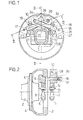
- a wheel hub 2 is mounted on an axle body 1, on which a drum-shaped brake disk 3 with screws 4 is attached.
- the wheel hub 2 is mounted on the axle body 1 in a known manner, so that the illustration of the bearing can be dispensed with.
- the adjusting device for the illustrated partial-pad disc brake consists of two symmetrical arrangements, which together produce the braking effect, so that the following description of an arrangement is sufficient to understand the invention.
- Bearing bolts 5 and 6 are fastened in or on the axle body 1 at a distance from one another on both sides of the plane of symmetry of the partial lining disc brake, on which bearings 7 and 8 for an inner brake shoe 9 and an outer brake shoe 10 are pivoted parallel to this on both sides of the axle body.
- the connections between the holders 7 and 8 and the brake shoes 9 and 10 are designed to be movable within narrow limits by means of bolts 11 and spherical bearing bushes 12, so that the brake shoes 9 and 10 can be moved parallel to the brake disc 3.
- two tie rods 13 are fastened, which penetrate bores 14 in the outer brake shoe 10 and have a fork head 15 on the outside, in each of which a brake lever 16 or 17 is pivotally mounted about an axis 18 or 19.
- the outer brake shoe 10 is mounted with a bush 20 on the shaft of the pull rod 13.
- Each brake lever 16 and 17 has on its free short lever arm a cam 21 which bears against an axially movably mounted adjusting bolt 22 which fits into a housing 23 formed by the outer brake shoe 10 intervenes.
- an adjusting body 24 is rotatably arranged in the housing, which has a recess 25 in its bottom for a coil spring 26.
- the housing 23 is covered with a cover 27, from which a square 28 of the adjusting body 24 protrudes.
- the adjusting bolt 22 and the adjusting body 24 act together via inclined surfaces 29 and 30 in order to compensate for the wear of brake pads 31 fastened to the brake shoes 9 and 10.
- a cylinder 32 is arranged in the outer brake shoe 10 with a piston 33 arranged therein, which acts on the brake lever 17 by means of a length-adjustable cover 34.
- the length of the bolt 34 is changed using an adjusting screw 35.
- the air play of the brake is determined by a bolt 36 which bears against the brake levers 16 and 17 and which is screwed into the inner brake shoe 9 and penetrates the outer brake shoe 10.
- a compression spring 37 is arranged, which braces the system for adjusting the air play against each other.
- the adjusting body 2 4 on the square 28 can be turned back into its starting position, the coil spring 26 being pretensioned at the same time.
Landscapes
- Engineering & Computer Science (AREA)
- General Engineering & Computer Science (AREA)
- Mechanical Engineering (AREA)
- Braking Arrangements (AREA)
Applications Claiming Priority (2)
| Application Number | Priority Date | Filing Date | Title |
|---|---|---|---|
| DE2902796 | 1979-01-25 | ||
| DE19792902796 DE2902796C2 (de) | 1979-01-25 | 1979-01-25 | Nachstellvorrichtung für eine Teilbelag-Scheibenbremse |
Publications (2)
| Publication Number | Publication Date |
|---|---|
| EP0014320A1 true EP0014320A1 (fr) | 1980-08-20 |
| EP0014320B1 EP0014320B1 (fr) | 1982-02-24 |
Family
ID=6061357
Family Applications (1)
| Application Number | Title | Priority Date | Filing Date |
|---|---|---|---|
| EP19800100080 Expired EP0014320B1 (fr) | 1979-01-25 | 1980-01-08 | Dispositif de rattrapage d'usure pour un frein à disque à garniture partielle |
Country Status (2)
| Country | Link |
|---|---|
| EP (1) | EP0014320B1 (fr) |
| DE (1) | DE2902796C2 (fr) |
Cited By (1)
| Publication number | Priority date | Publication date | Assignee | Title |
|---|---|---|---|---|
| EP0073320A1 (fr) * | 1981-08-12 | 1983-03-09 | Bergische Achsenfabrik Fr. Kotz & Söhne | Dispositif de manoeuvre et de réajustage pour freins à disques à garnitures en segments |
Citations (6)
| Publication number | Priority date | Publication date | Assignee | Title |
|---|---|---|---|---|
| DE1080874B (de) * | 1953-10-28 | 1960-04-28 | Dunlop Rubber Co | Scheibenbremse, insbesondere fuer Kraftfahrzeuge |
| DE1164854B (de) * | 1954-12-11 | 1964-03-05 | Dunlop Rubber Co | Teilbelagscheibenbremse, insbesondere fuer Motorfahrzeuge u. dgl. |
| DE1475501B2 (de) * | 1965-11-27 | 1972-01-27 | Alfred Teves Gmbh, 6000 Frankfurt | Mechanisch zu betaetigende teilbelagscheibenbremse mit selbstverstaerkender bremswirkung |
| DE2448787A1 (de) * | 1974-10-12 | 1976-04-15 | Bergische Achsen Kotz Soehne | Teilbelag-scheibenbremse fuer kraftfahrzeuge |
| DE1675155B2 (de) * | 1968-01-13 | 1976-05-06 | Selbsttaetige nachstellvorrichtung zum verschleissausgleich des bremsbelages einer elektromagnetisch lueftbaren federdruckscheibenbremse | |
| DE2741093A1 (de) * | 1977-09-13 | 1979-03-15 | Bergische Achsen Kotz Soehne | Betaetigungs- und nachstellvorrichtung fuer eine teilbelag-scheibenbremse |
Family Cites Families (5)
| Publication number | Priority date | Publication date | Assignee | Title |
|---|---|---|---|---|
| US1455587A (en) * | 1919-11-11 | 1923-05-15 | Powell Evans | Clutch |
| DE704791C (de) * | 1939-06-03 | 1941-04-07 | Goetzewerk Friedrich Goetze Ak | Zentral betaetigte Nachstellvorrichtung fuer die Druckhebel von Lamellenkupplungen, insbesondere von Kraftfahrzeugen |
| US2690391A (en) * | 1952-09-23 | 1954-09-28 | Chemical Construction Corp | Use of hydrogen in precipitation of cobalt carbonate |
| FR1372470A (fr) * | 1963-05-21 | 1964-09-18 | Dba Sa | Dispositif de réglage automatique et son procédé de fabrication |
| DE2309757A1 (de) * | 1973-02-27 | 1974-09-12 | Segaric S A | Selbsttaetige vorrichtung zum nachstellen einer scheibenbremse |
-
1979
- 1979-01-25 DE DE19792902796 patent/DE2902796C2/de not_active Expired
-
1980
- 1980-01-08 EP EP19800100080 patent/EP0014320B1/fr not_active Expired
Patent Citations (6)
| Publication number | Priority date | Publication date | Assignee | Title |
|---|---|---|---|---|
| DE1080874B (de) * | 1953-10-28 | 1960-04-28 | Dunlop Rubber Co | Scheibenbremse, insbesondere fuer Kraftfahrzeuge |
| DE1164854B (de) * | 1954-12-11 | 1964-03-05 | Dunlop Rubber Co | Teilbelagscheibenbremse, insbesondere fuer Motorfahrzeuge u. dgl. |
| DE1475501B2 (de) * | 1965-11-27 | 1972-01-27 | Alfred Teves Gmbh, 6000 Frankfurt | Mechanisch zu betaetigende teilbelagscheibenbremse mit selbstverstaerkender bremswirkung |
| DE1675155B2 (de) * | 1968-01-13 | 1976-05-06 | Selbsttaetige nachstellvorrichtung zum verschleissausgleich des bremsbelages einer elektromagnetisch lueftbaren federdruckscheibenbremse | |
| DE2448787A1 (de) * | 1974-10-12 | 1976-04-15 | Bergische Achsen Kotz Soehne | Teilbelag-scheibenbremse fuer kraftfahrzeuge |
| DE2741093A1 (de) * | 1977-09-13 | 1979-03-15 | Bergische Achsen Kotz Soehne | Betaetigungs- und nachstellvorrichtung fuer eine teilbelag-scheibenbremse |
Cited By (1)
| Publication number | Priority date | Publication date | Assignee | Title |
|---|---|---|---|---|
| EP0073320A1 (fr) * | 1981-08-12 | 1983-03-09 | Bergische Achsenfabrik Fr. Kotz & Söhne | Dispositif de manoeuvre et de réajustage pour freins à disques à garnitures en segments |
Also Published As
| Publication number | Publication date |
|---|---|
| DE2902796A1 (de) | 1980-07-31 |
| DE2902796C2 (de) | 1982-04-29 |
| EP0014320B1 (fr) | 1982-02-24 |
Similar Documents
| Publication | Publication Date | Title |
|---|---|---|
| DE69713135T2 (de) | Aufhängungs- und bremseinheit | |
| DE1090984B (de) | Scheibenbremse, insbesondere fuer Kraftfahrzeuge | |
| DE1575894B2 (de) | Betaetigungsvorrichtung fuer eine scheibenbremse | |
| EP0731286B1 (fr) | Frein à disque pour véhicules, notamment véhicules ferroviaires | |
| DE2346828A1 (de) | Nachstellvorrichtung fuer bremsen | |
| DE4210828C2 (de) | Bremszange für eine elektrohydraulisch betätigbare Zangenscheibenbremse, insbesondere für Straßenbahnwagen | |
| DE7915980U1 (de) | Bremsbetaetigungshebel fuer eine selbstzentrierende teilbelag-scheibenbremse | |
| DE4407293C1 (de) | Bremszange für Scheibenbremsen von Schienenfahrzeugen | |
| EP0014320B1 (fr) | Dispositif de rattrapage d'usure pour un frein à disque à garniture partielle | |
| DE69904093T2 (de) | Scheibenbremsvorrichtung | |
| DE19525722C2 (de) | Zuspannvorrichtung für eine Scheibenbremse | |
| DE2703389A1 (de) | Scheibenbremse | |
| DE8320022U1 (de) | Betätigungseinrichtung für eine Scheibenbremse | |
| DE2549007A1 (de) | Feststellbremse, insbesondere fuer schienenfahrzeuge | |
| EP0594057B1 (fr) | Dispositif pour le mouvement parallèle d'un sabot de frein | |
| DE1920593U (de) | Scheibenbremse, insbesondere fuer hydraulische bremsanlagen. | |
| DE924606C (de) | Backen- oder Bandbremse, insbesondere fuer Kraftfahrzeuge | |
| EP0001045B1 (fr) | Dispositif de rattrapage de jeu pour frein à disque à garnitures en segments | |
| EP0029916A1 (fr) | Frein à disque, en particulier pour véhicules à moteur | |
| DE1121103B (de) | Bremseinrichtung fuer Fahrzeuge | |
| DE102017125867A1 (de) | Nachstelleinrichtung einer Scheibenbremse | |
| EP0695402B1 (fr) | Frein a disque | |
| DE1750105C3 (de) | Vorrichtung zum Verändern des Bremsmoments bei Scheibenreibungsbremsen | |
| EP0186767A1 (fr) | Liaison articulée entre un cylindre de frein et un levier de frein | |
| DE1084293B (de) | Bremseinrichtung fuer Schienenfahrzeuge |
Legal Events
| Date | Code | Title | Description |
|---|---|---|---|
| PUAI | Public reference made under article 153(3) epc to a published international application that has entered the european phase |
Free format text: ORIGINAL CODE: 0009012 |
|
| AK | Designated contracting states |
Designated state(s): FR GB IT NL SE |
|
| 17P | Request for examination filed | ||
| ITF | It: translation for a ep patent filed | ||
| GRAA | (expected) grant |
Free format text: ORIGINAL CODE: 0009210 |
|
| AK | Designated contracting states |
Designated state(s): FR GB IT NL SE |
|
| PGFP | Annual fee paid to national office [announced via postgrant information from national office to epo] |
Ref country code: NL Payment date: 19821209 Year of fee payment: 4 |
|
| PGFP | Annual fee paid to national office [announced via postgrant information from national office to epo] |
Ref country code: FR Payment date: 19821223 Year of fee payment: 4 |
|
| PG25 | Lapsed in a contracting state [announced via postgrant information from national office to epo] |
Ref country code: SE Effective date: 19840109 |
|
| PG25 | Lapsed in a contracting state [announced via postgrant information from national office to epo] |
Ref country code: NL Effective date: 19840801 |
|
| NLV4 | Nl: lapsed or anulled due to non-payment of the annual fee | ||
| PG25 | Lapsed in a contracting state [announced via postgrant information from national office to epo] |
Ref country code: FR Free format text: LAPSE BECAUSE OF NON-PAYMENT OF DUE FEES Effective date: 19840928 |
|
| GBPC | Gb: european patent ceased through non-payment of renewal fee | ||
| REG | Reference to a national code |
Ref country code: FR Ref legal event code: ST |
|
| PG25 | Lapsed in a contracting state [announced via postgrant information from national office to epo] |
Ref country code: GB Effective date: 19881118 |
|
| EUG | Se: european patent has lapsed |
Ref document number: 80100080.3 Effective date: 19850604 |
|
| PLBE | No opposition filed within time limit |
Free format text: ORIGINAL CODE: 0009261 |
|
| STAA | Information on the status of an ep patent application or granted ep patent |
Free format text: STATUS: NO OPPOSITION FILED WITHIN TIME LIMIT |