EP0014430A1 - Procédé et appareillage pour la fermeture des pointes de bas - Google Patents
Procédé et appareillage pour la fermeture des pointes de bas Download PDFInfo
- Publication number
- EP0014430A1 EP0014430A1 EP80100469A EP80100469A EP0014430A1 EP 0014430 A1 EP0014430 A1 EP 0014430A1 EP 80100469 A EP80100469 A EP 80100469A EP 80100469 A EP80100469 A EP 80100469A EP 0014430 A1 EP0014430 A1 EP 0014430A1
- Authority
- EP
- European Patent Office
- Prior art keywords
- hose
- finger pieces
- sewing
- toe
- toe section
- Prior art date
- Legal status (The legal status is an assumption and is not a legal conclusion. Google has not performed a legal analysis and makes no representation as to the accuracy of the status listed.)
- Granted
Links
- 238000000034 method Methods 0.000 title claims description 6
- 238000009958 sewing Methods 0.000 claims abstract description 65
- 239000000463 material Substances 0.000 claims description 24
- 239000004744 fabric Substances 0.000 claims description 16
- 230000006835 compression Effects 0.000 claims description 2
- 238000007906 compression Methods 0.000 claims description 2
- 238000004519 manufacturing process Methods 0.000 abstract description 11
- 238000010276 construction Methods 0.000 abstract description 4
- 230000007246 mechanism Effects 0.000 description 6
- 230000008569 process Effects 0.000 description 3
- NJPPVKZQTLUDBO-UHFFFAOYSA-N novaluron Chemical compound C1=C(Cl)C(OC(F)(F)C(OC(F)(F)F)F)=CC=C1NC(=O)NC(=O)C1=C(F)C=CC=C1F NJPPVKZQTLUDBO-UHFFFAOYSA-N 0.000 description 2
- 238000013459 approach Methods 0.000 description 1
- 230000015572 biosynthetic process Effects 0.000 description 1
- 230000000295 complement effect Effects 0.000 description 1
- 230000008878 coupling Effects 0.000 description 1
- 238000010168 coupling process Methods 0.000 description 1
- 238000005859 coupling reaction Methods 0.000 description 1
- 230000006872 improvement Effects 0.000 description 1
- 230000004048 modification Effects 0.000 description 1
- 238000012986 modification Methods 0.000 description 1
- 238000005096 rolling process Methods 0.000 description 1
- 238000004804 winding Methods 0.000 description 1
Images


Classifications
-
- D—TEXTILES; PAPER
- D05—SEWING; EMBROIDERING; TUFTING
- D05B—SEWING
- D05B23/00—Sewing apparatus or machines not otherwise provided for
- D05B23/007—Sewing units for assembling parts of knitted panties or closing the stocking toe part
- D05B23/009—Toe closers
-
- D—TEXTILES; PAPER
- D05—SEWING; EMBROIDERING; TUFTING
- D05D—INDEXING SCHEME ASSOCIATED WITH SUBCLASSES D05B AND D05C, RELATING TO SEWING, EMBROIDERING AND TUFTING
- D05D2207/00—Use of special elements
- D05D2207/02—Pneumatic or hydraulic devices
- D05D2207/04—Suction or blowing devices
-
- Y—GENERAL TAGGING OF NEW TECHNOLOGICAL DEVELOPMENTS; GENERAL TAGGING OF CROSS-SECTIONAL TECHNOLOGIES SPANNING OVER SEVERAL SECTIONS OF THE IPC; TECHNICAL SUBJECTS COVERED BY FORMER USPC CROSS-REFERENCE ART COLLECTIONS [XRACs] AND DIGESTS
- Y10—TECHNICAL SUBJECTS COVERED BY FORMER USPC
- Y10S—TECHNICAL SUBJECTS COVERED BY FORMER USPC CROSS-REFERENCE ART COLLECTIONS [XRACs] AND DIGESTS
- Y10S112/00—Sewing
- Y10S112/02—Air work handling
Definitions
- the present invention relates to improved method and apparatus for closing the toe end of a hose, and more particularly relates to improvement in formation of an arc sew line on the toe section of a hose on any conventional sewing machine of the fixed type without requirement for any complicated accessories.
- Toe closer One example of the conventional apparatus for closing the toe end of a seamless hose (hereinafter referred to simply as "toe closer") is disclosed in USP. NOS 3,941,069 and 3,952,673 and now serves for actual production of seamless hoses.
- a pair of finger pieces are inserted into a material seamless hose prepared inside out in order to streach it laterally.
- the material seamless hosevis then transferred to a holder of a sewing mechanism and the finger pieces withdraw from the interior of the material seamless hose so held by the holder in order to enable sewing of its rear toe section. Thereafter, the rear toe section is removed from the holder and pneumatically passed to the next process for completion of toe closing.
- the average production rate on the above-described conventional toe closer is about 400 dozens per 8 hours.
- This relatively low production rate is caused by the disadvantage that, even when the sewing machine is of a fixed type, it is required to vertically clamp the toe section of a material seamless hose in free state by a holder and to rotate circularly the holder, therby provisionally disabling the lateral movement of the material seamless hose.
- the above-described curved toe closing on hoses is practiced by tactful used of a specially designed cam mechanism in combination with timely ejection of air jet in the sewing region.
- the cam mechanism is operationally coupled to a pair of finger pieces adapted for holding each material hose so that the toe section of the material hose held in a prescribed arc form is forced to travel along an arc locus for sewing on any conventional sewing machine of a fixed type while concurrently autting off the outer unnecessary cloth section.
- This allows easy production of a hose having the round toe section of a sufficiently small radius of curvature. Since the sewing operation does not intercept the lateral movement of the material hose at all, employment of the present invention assures high production rate such as 600 dozens per 8 hours.
- material hoses can be fed to the sewing machine at every 2 seconds.
- FIG. 1 contains an elongated main section 1 of the hose made of a thin cloth, a welt section 2 containing rubber threads and integral of one longitudinal end of the main section 1 and a toe section 3 made of a thick cloth and connected to another longitudinal end of the main section 1 along a uniting line 4.
- FIG. 2 A hose obtained by properly closing the toe end of the above-described material is shown in Fig. 2.
- the position of the uniting line 4 is unchanged even after closing of the toe end and the uniting line 4 remains substantially straight as in the material shown in Fig. 1.
- the toe section 3 outside the uniting line 4 has a round fringe 6 and a sew line 5 of a smaller diameter. with this shape, the toe section 3 of the hose fully covers the foot fingers of the user in use.
- the toe section 3 when the hose is provided with a curved uniting line 14 and the toe section 3 assumes a crescent shape as shown in Fig. 3, the toe section 3 is unable to fully cover the foot fingers in use and the fingers are placed in touch with the main section 1 also.
- the present invention contemplates production of hoses of the type shown in Fig. 2 which assures comfortable fit to users' feet.
- the present invention also contemplates such production without use of any complicated sewing mechanism by making use of large stretchability inherent to hosieries.
- the toe end closing process in accordance with the present invention includes the following sequential operational steps in order to complete its one cycle operation.
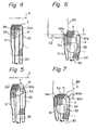
- Fig. 4 the main section 1 of a hose to be closed is inserted over a pneumatic suction pipe 30 fixed to a holder and a pair of finger pieces 31 and 32 arranged on both lateral sides of the suction pipe 30, with the toe section 3 extending beyond the mouth of the suction pipe 30.
- This state of the hose is obtained by registering ends of the uniting line 4 on the hose at front corners 31a, 32a of the finger pieces 31 and 32, respectively.
- the finger pieces 31 and 32 are moved laterally from each other as shown in Fig. 5 while moving forwards with the hose with respect to the suction pipe 30.
- the main section 1 of the hose is made of a highly stretchable hoisery, it has a constant and strong urge to resume its original shape when laterally stretched.
- the toe section 3 assumes a roughly arched shape as shown in Fig. 6.
- the hose is registered at the sew line 5 and moved laterally in a direction perpendicular to the sewing machine. Concurrently with this lateral movement, the hose is moved along a curved locus 5a by means of the later described cam mechanism, thereby forming an arched sew line 5b shown in Fig. 7, which is roughly symmetric to the curved locus 5a with respect to the sew line 5. Thereafter, the hose is released from holding, Then, due to the excellent resilience of the hose, the resultant hose r possesses the curved sew line 5 (toe close line) and the round fringe 6 as shown in Fig. 2.
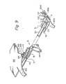
- the construction of the holder for the finger pieces 31 and 32 and the suction pipe 30 is shown in detail in Figs. 8A through 8C.
- the head piece 33 is fixed to the front end of the suction pipe 30.
- a pair of guide grooves 34 are formed in the side surfaces of the head piece 33.
- a middle slider 36 and a rear slider 37 are assemble to the suction pipe 30 in a fashion to slide along the latter.
- the front corners 31a and 32a of the finger pieces 31 and 32 are slidably engageable with the associated guide grooves 34 formed in the head piece 33. Pivotal couplings are established between the middles of the finger pieces 31 and 32 and the middle slider 36 by means'by pins 35.
- the rear slider 37 is provided on its top with a rotary disc 40 adapted for driving the finger pieces 31, 32 for the lateral movement.
- a slot is formed through the rear slider 37 in the direction normal to the longitudinal direction of the finger pieces 31 and 32.
- a pair of arc grooves are formed in the bottom of the rotary disc 40 at symmetric positions with respect to its center whilst extending over a prescribed center angle.
- Upright pins are secured to the tops of the finger pieces 31 and 32 at positions adjacent their rear ends, which slidably engage the associated arc grooves in the rotary disc 40 via the slot in the rear slider.
- the finger pieces 31 and 32, the middle slider 36 and the rear slider 37 form a unit A which is movable along the suction pipe 30 towards and away from the head price 33.
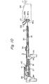
- a bracket 44 is arranged movably along the framework of the apparatus and securedly carries the above-described suction pipe 30.
- the axial direction of the suction pipe 30 is normal to the moving direction of the bracket 44 along the framework.
- the bracket 44 is located between the middle slider 36 and the rear slider 37 and a compression spring 81 is interposed between the bracket 44 and the rear slider 37 whilst winding around the suction pipe 30.
- a cam plate 82 is secured to the framework of the apparatus at a position above the rear slider 37 having a top rotary cam follower 41.
- the cam plate 82 is provided with continuous cam surfaces 83, 84 and 85 engageable with the cam follower 41, and an arc cam surface 86.
- the cam surfaces 83 and 86 are both concave in the front side of the cam plate 82.
- the unit A As the bracket 44 moves laterally in Fig. 9, the unit A is forced to move forwards relative to the suction pipe 30, whilst surmounting the repulsion of the spring 81, due to the sliding contact of the cam follower 41 on the rear slider 37 with the cam surface 82 on the cam plate 83. As the cam follower 41 comes in contact with the next cam surface 84, the unit A and the suction pipe 30 assume the relative position shown in Fig. 6.
- the cam follow 41 comes in contact with the cam surface 85 in the form of a small projection at the terminal of the cam surface 84 and the unit A further moves forwards from the position shown in Fig. 6 so that the beginning end of the toe section 3 is fed into a space between a cloth clamper 89b and a needle plate 89c on a sewing machine 89.
- FIG. 15 A modification of the sewing machine 89 advantageously usable for toe closing in the present invention is shown in Fig. 15, in which the sewing machine 89 is swingable about the axis of its needle 89a in synchronism with the arc movement of the toe section 3 of the hose so that the arched sew line 5b intersects always normally the center of the arc movement of the toe section 3, thereby assuring further stable toe closing operation.
- the sewing machine 89 is accompanied with proper means for sewing the sewing machine 89 about the axis of the needle 89a.
- the swinging means comprises, for example, a pneumatic pressure cylinder 110 having a piston 111.
- the outer end of the piston 111 is pivoted to one end of a lever 112 which is pivotal at another end to the axis of the needle 89a and comovably coupled to the sewing machine 89.
- the lever 112 with the sewing machine swings about the axis of the needle 89a. Moving speed of the piston 111 is adjusted so as to synchronize with the speed of the finger pieces 31 and 32 in their lateral movement.
- the sewing machine 89 is associated with complementary means for stably and successfully feeding the toe section into the space between the cloth clamper 89b and the needle plate 89c.
- the feeding means includes two air jet nozzles 101 and 102 arranged close to the above-described space.
- one jet nozzle 102 is provided in its bottom surface a number of aligned fine ejection apertures 101a so that air jets flows in the direction shown with arrors. These air jets let the free toe section 3, which extends beyond the foremost ends of the finger pieces 31 and 32, extend well following the top surface of the needle plate 89c so that the toe section 3 can be fed into the above-described space in a stable state.
- Another jet nozzle 102 is provided with a flat distal mouth which is directed towards the front end of the cloth clamper 89b. Air jet is ejected by this jet nozzle 102 only when the leading and tail terminals of the toe section 3 pass by the front section of the cloth clamper 89b so that the terminals of the toe section 3 can be fed to the space between the cloth clamper 89b and the needle plate 89c without fail whilst stretching the terminals by the blow of the air jet.
- FIG. 14 One example of the toe closing machine embodying the present invention is shown in Fig. 14, in which ten sets of brackets 44 arranged at equal intervals travel along an endless course set on an oblong horizontal pedestal 10.
- The. brackets 44 are coupled in series by means of chain links 45 pivotted at both ends to adjacent brackets 44.
- a drive shaft 20 and a driven shaft 76 are rotatably arranged on the pedestal 10.
- a sprocket 21 secured on the drive shaft 20 and a sprocket 23 secured on the driven shaft 76 are operationally connected by on endless chain 22.
- a drive drum 49 is secured to the drive shaft 20 whereas a guide drum 75 is secured to the driven shaft 76.
- the drive drum 49 is provided in its periphery a plurality of recesses 47 formed at equal intervals and each bracket 44 is provided with a top projection 48 engageable with the recesses 47 in the drive drum 49.
- the pitch between adjacent recesses 47 in the drive drum 49 is tantamount to that between the projections 48 on adjacent brackets 44.
- the bracket 44 During the travel of the bracket 44 from station I to station II, an operator of the machine subjects the toe section 3 of a hose to pneumatic suction by the suction pipe 30 accompanying a bracket 44 whilst holding its welt section. After cancelling the pneumatic suction, the welt section is folded up to cover the outer periphery of the suction pipe 30 and the remnant is rolled up positively and automatically on the suction pipe in order to set the hose inside out. In this case, the toe section 3 is left outside the suction pipe 30 so that both terminals of the uniting line 4 can be registered at the front corners 31a and 32a of the finger pieces 31 and 32 in the open state in Fig. 4.
- the pair of finger pieces 31 and 32 are brought into the open state after movement from each other in order to stretch the toe section outwards as shown in Fig. 5 and the finger pieces 31 and 32 are driven for movement towards the sewing machine as shown in Fig. 6.
- the cam follower 41 shifts laterally following the contours of the cam surfaces 85 and 86 and, being asisted by repulsion of the spring 81, the finger pieces 31 and 32 holding the toe section 3 moves laterally along the arc locus 41b in Fig. 12 which corresponds to the countours of the cam surfaces 85 and 86.
- the cam follower 41 comes in contact with the arc cam surface 86 of the cam plate 82 and ejection of the jet air by the jet nozzle 102 is stopped.
- the finger pieces 31 and 32 holding the toe section 3 moves away from the needle 89a on the sewing machine 89 along an arc locus.
- the finger pieces 31 and 32 holding the toe section moves laterally towards the needle 89a along an arc locus.
- the finger pieces 31 and 32 holding the toe section 3 also travel laterally along the arc locus 41b in Fig. 12.
- the toe section 3 is fed into the space between the cloth clamper 89b and the needle plate 89c, brought towards the needle 89a assuming an arc shape due to the operation of a feed wheel (not shown) of the sewing machine 89, and closed finally.
- the other jet nozzle 101 is actuated during the period in which the cam follower 41 travels from the starting point 86a to the final point 86c on the arc cam surface 86.
- ejection of air jets by the jet nozzle 101 lasts from starting to end of the toe closing operation so that the free toe section 3 should constantly well follow the top face of the needle plate 89c.
- the finger pieces 31 recedes off the sewing machine 89 and are brought into the closed state during the recession.
- pneumatic suction is revived in order to suck the toe section 3 into the suction pipe 30 while rolling back the hose rolled up on the outer side of the suction pipe 30.
- the toe closed hose in the initial state is pneumatically passed to the next process as the bracket 44 travels from station VIII to station IX.
Landscapes
- Engineering & Computer Science (AREA)
- Textile Engineering (AREA)
- Sewing Machines And Sewing (AREA)
Applications Claiming Priority (2)
| Application Number | Priority Date | Filing Date | Title |
|---|---|---|---|
| JP54010204A JPS5831953B2 (ja) | 1979-01-30 | 1979-01-30 | ホ−スのトウ部をクロ−ズする方法及び装置 |
| JP10204/79 | 1979-01-30 |
Publications (2)
| Publication Number | Publication Date |
|---|---|
| EP0014430A1 true EP0014430A1 (fr) | 1980-08-20 |
| EP0014430B1 EP0014430B1 (fr) | 1983-06-15 |
Family
ID=11743734
Family Applications (1)
| Application Number | Title | Priority Date | Filing Date |
|---|---|---|---|
| EP80100469A Expired EP0014430B1 (fr) | 1979-01-30 | 1980-01-30 | Procédé et appareillage pour la fermeture des pointes de bas |
Country Status (4)
| Country | Link |
|---|---|
| US (1) | US4343254A (fr) |
| EP (1) | EP0014430B1 (fr) |
| JP (1) | JPS5831953B2 (fr) |
| DE (1) | DE3063717D1 (fr) |
Cited By (1)
| Publication number | Priority date | Publication date | Assignee | Title |
|---|---|---|---|---|
| EP0533637A1 (fr) * | 1991-09-18 | 1993-03-24 | SOLIS S.r.l. | Machine pour la couture automatique de la pointe du pied de deux bas, spécialement des collants |
Families Citing this family (4)
| Publication number | Priority date | Publication date | Assignee | Title |
|---|---|---|---|---|
| US4921177A (en) * | 1988-10-18 | 1990-05-01 | Figgie International Inc. | String positioning device and method |
| IT1246679B (it) * | 1991-02-26 | 1994-11-24 | Solis Srl | Metodo per variare la curvatura della punta cucita delle calze con una macchina cucipunte e dispositivo per attuare il detto metodo. |
| US5566633A (en) * | 1993-12-28 | 1996-10-22 | G&G Sewing Machine Company, Inc. | Sewing machine with tape feed and pneumatic devices for clamping workpieces |
| ITBS20050034A1 (it) * | 2005-03-14 | 2006-09-15 | Santoni & C Spa | Macchina e metodo per la movimentazione di manufatti tubolari |
Citations (4)
| Publication number | Priority date | Publication date | Assignee | Title |
|---|---|---|---|---|
| US3941069A (en) * | 1973-12-28 | 1976-03-02 | Takatori Machinery Works, Ltd. | Automatic method and apparatus for closing the toe of seamless hose |
| US3952673A (en) * | 1973-12-28 | 1976-04-27 | Takatori Machinery Works, Ltd. | Automatic method and apparatus for closing the toe of seamless hose |
| US4133280A (en) * | 1976-10-26 | 1979-01-09 | Takatori Machinery Works, Ltd. | Automatic method and apparatus for closing a toe end of a hose utilizing a straight line stitch |
| LU81445A1 (fr) * | 1978-12-06 | 1979-09-12 | Aznar Sa | Procede et machine pour la couture automatique de renforts sur vetements |
Family Cites Families (4)
| Publication number | Priority date | Publication date | Assignee | Title |
|---|---|---|---|---|
| FR1583500A (fr) * | 1967-10-02 | 1969-10-31 | ||
| JPS544308B2 (fr) * | 1973-02-05 | 1979-03-05 | ||
| GB1575756A (en) * | 1976-02-20 | 1980-09-24 | Mabi Srl | Machine for sewing the toes of stockings |
| JPS52152360A (en) * | 1976-06-11 | 1977-12-17 | Takatori Kikai Seisakusho Kk | Method and device for automatically sewing rectilinearly seamless stocking toe by stationary sewing machine |
-
1979
- 1979-01-30 JP JP54010204A patent/JPS5831953B2/ja not_active Expired
-
1980
- 1980-01-30 US US06/116,960 patent/US4343254A/en not_active Expired - Lifetime
- 1980-01-30 DE DE8080100469T patent/DE3063717D1/de not_active Expired
- 1980-01-30 EP EP80100469A patent/EP0014430B1/fr not_active Expired
Patent Citations (4)
| Publication number | Priority date | Publication date | Assignee | Title |
|---|---|---|---|---|
| US3941069A (en) * | 1973-12-28 | 1976-03-02 | Takatori Machinery Works, Ltd. | Automatic method and apparatus for closing the toe of seamless hose |
| US3952673A (en) * | 1973-12-28 | 1976-04-27 | Takatori Machinery Works, Ltd. | Automatic method and apparatus for closing the toe of seamless hose |
| US4133280A (en) * | 1976-10-26 | 1979-01-09 | Takatori Machinery Works, Ltd. | Automatic method and apparatus for closing a toe end of a hose utilizing a straight line stitch |
| LU81445A1 (fr) * | 1978-12-06 | 1979-09-12 | Aznar Sa | Procede et machine pour la couture automatique de renforts sur vetements |
Cited By (1)
| Publication number | Priority date | Publication date | Assignee | Title |
|---|---|---|---|---|
| EP0533637A1 (fr) * | 1991-09-18 | 1993-03-24 | SOLIS S.r.l. | Machine pour la couture automatique de la pointe du pied de deux bas, spécialement des collants |
Also Published As
| Publication number | Publication date |
|---|---|
| JPS55101292A (en) | 1980-08-01 |
| JPS5831953B2 (ja) | 1983-07-09 |
| DE3063717D1 (en) | 1983-07-21 |
| EP0014430B1 (fr) | 1983-06-15 |
| US4343254A (en) | 1982-08-10 |
Similar Documents
| Publication | Publication Date | Title |
|---|---|---|
| JP2752758B2 (ja) | ブランクの連続送り方法及びその装置 | |
| US4133280A (en) | Automatic method and apparatus for closing a toe end of a hose utilizing a straight line stitch | |
| US3941069A (en) | Automatic method and apparatus for closing the toe of seamless hose | |
| US3442505A (en) | Automatic apparatus for separating the top workpiece from a stack of fabric workpieces and for delivering the separated workpieces | |
| US4164279A (en) | Assembly for feeding objects from a conveyor to a printing station and a printing machine having such a feeding assembly | |
| US3859938A (en) | Automatic apparatus for closing the toe of a seamless stocking | |
| EP0255496B1 (fr) | Dispositif de formation semi-automatique d'enveloppes, c.à-d. de recouvrements de matelas ou similaires | |
| US4343254A (en) | Method and apparatus for closing the toe end of a hose | |
| US3738294A (en) | Apparatus for closing the toe of a stocking | |
| DK143611B (da) | Maskine til syning af taaen paa en stroempe | |
| US4120251A (en) | Automatic method and apparatus for closing a toe end of a seamless hose material utilizing a straight line stitching by means of a stationarily disposed sewing machine | |
| US4620494A (en) | Conveyor for use in carrying leg parts of half made pantyhose in an integrated pantyhose sewing machine | |
| US3875880A (en) | Apparatus adapted for use in the toe closing of hosiery | |
| FI79149C (fi) | Mekanism foer utdragning av en laongstraeckt sydd produkt ur symaskin. | |
| EP0155976B1 (fr) | Machine à former des garnitures en matière plastique dans des bouchons creux, comme les bouchons à vis et les capsules | |
| KR920008100B1 (ko) | 연이어 있는 거의 직사각형 플라이천들을 연속 슬라이드 파스너 체인에 꿰매는 방법 및 장치 | |
| US4383490A (en) | Hosiery toe closing machine | |
| US4566846A (en) | Carton transfer apparatus with effective constant length inverting arm | |
| US4321881A (en) | Method and apparatus for inserting a gusset in panti-hose | |
| US4037547A (en) | Clamshell guide to apply annular elastic bands on clothes | |
| US4267785A (en) | Automatic apparatus for feeding and fitting a gore piece to the inside thigh opening of a stocking material | |
| JP2542317B2 (ja) | ストッキングの爪先の自動縫製機 | |
| US3952673A (en) | Automatic method and apparatus for closing the toe of seamless hose | |
| EP0042651B1 (fr) | Dispositif de fabrication d'un ourlet sur les bords d'extrémité d'une pièce de tissu, par exemple un drap de lit | |
| US4481064A (en) | Dual rotary head banding machine |
Legal Events
| Date | Code | Title | Description |
|---|---|---|---|
| PUAI | Public reference made under article 153(3) epc to a published international application that has entered the european phase |
Free format text: ORIGINAL CODE: 0009012 |
|
| AK | Designated contracting states |
Designated state(s): DE FR GB IT |
|
| 17P | Request for examination filed | ||
| R17P | Request for examination filed (corrected) | ||
| ITF | It: translation for a ep patent filed | ||
| GRAA | (expected) grant |
Free format text: ORIGINAL CODE: 0009210 |
|
| AK | Designated contracting states |
Designated state(s): DE FR GB IT |
|
| REF | Corresponds to: |
Ref document number: 3063717 Country of ref document: DE Date of ref document: 19830721 |
|
| KL | Correction list |
Free format text: 83/04 ZEICHNUNG |
|
| ET | Fr: translation filed | ||
| PLBE | No opposition filed within time limit |
Free format text: ORIGINAL CODE: 0009261 |
|
| STAA | Information on the status of an ep patent application or granted ep patent |
Free format text: STATUS: NO OPPOSITION FILED WITHIN TIME LIMIT |
|
| 26N | No opposition filed | ||
| PGFP | Annual fee paid to national office [announced via postgrant information from national office to epo] |
Ref country code: DE Payment date: 19901222 Year of fee payment: 12 |
|
| PGFP | Annual fee paid to national office [announced via postgrant information from national office to epo] |
Ref country code: FR Payment date: 19910102 Year of fee payment: 12 |
|
| PGFP | Annual fee paid to national office [announced via postgrant information from national office to epo] |
Ref country code: GB Payment date: 19910125 Year of fee payment: 12 |
|
| ITTA | It: last paid annual fee | ||
| PG25 | Lapsed in a contracting state [announced via postgrant information from national office to epo] |
Ref country code: GB Effective date: 19920130 |
|
| GBPC | Gb: european patent ceased through non-payment of renewal fee | ||
| PG25 | Lapsed in a contracting state [announced via postgrant information from national office to epo] |
Ref country code: FR Effective date: 19920930 |
|
| PG25 | Lapsed in a contracting state [announced via postgrant information from national office to epo] |
Ref country code: DE Effective date: 19921001 |
|
| REG | Reference to a national code |
Ref country code: FR Ref legal event code: ST |