EP0014487A2 - Plaque de cuisson encastrable - Google Patents
Plaque de cuisson encastrable Download PDFInfo
- Publication number
- EP0014487A2 EP0014487A2 EP80200025A EP80200025A EP0014487A2 EP 0014487 A2 EP0014487 A2 EP 0014487A2 EP 80200025 A EP80200025 A EP 80200025A EP 80200025 A EP80200025 A EP 80200025A EP 0014487 A2 EP0014487 A2 EP 0014487A2
- Authority
- EP
- European Patent Office
- Prior art keywords
- cooking hob
- drip plate
- box casing
- burner
- bracket
- Prior art date
- Legal status (The legal status is an assumption and is not a legal conclusion. Google has not performed a legal analysis and makes no representation as to the accuracy of the status listed.)
- Granted
Links
Images


Classifications
-
- F—MECHANICAL ENGINEERING; LIGHTING; HEATING; WEAPONS; BLASTING
- F24—HEATING; RANGES; VENTILATING
- F24C—DOMESTIC STOVES OR RANGES ; DETAILS OF DOMESTIC STOVES OR RANGES, OF GENERAL APPLICATION
- F24C3/00—Stoves or ranges for gaseous fuels
- F24C3/08—Arrangement or mounting of burners
- F24C3/085—Arrangement or mounting of burners on ranges
Definitions
- This invention relates to an improved cooking hob which is of very limited thickness and is equipped in such a manner as to enable it to be easily and rapidly built into the top of the corresponding housing cabinet.
- Cooking hobs are becoming increasingly more used in modern kitchen furnishing systems, because of their low cost and overall size relative to the normal domestic cookers.
- the cooking hobs normally available commercially are usually constituted essentially by a lower box casing for containing the gas taps and conduits and the corresponding burners, and an upper cover or drip plate resting on the perimetral edge of the box casing, and on which a set of gas rings is disposed. An electrical hot plate is sometimes provided between these gas rings.
- known cooking hobs are provided with a suitable control panel for receiving the gas tap knobs and other controls, and is disposed either on the front horizontal edge of the drip plate or nn one of its horizontal side edges.
- this built-in assembly comprises forming a suitable aperture in the corresponding top, then positioning the lower box casing of the cooking hob in said aperture so that only the gas rings and support grid for the cooking utensils project above the top of the cabinet.
- a first drawback derives from the fact that known cooking hobs have an excessive thickness, because of which they are poorly suitable for building into the cabinet tops, as they then project into the internal compartment of the cabinet. This drawback arises for example in the case of cabinets for housing a dishwasher. Other similar cases are cabinets for housing a washing machine or a small refrigerator. This is because in such cases the domestic appliance completely occupies the interior of the corresponding cabinet, because of which a known cooking hob cannot be built into its top because of the excessive thickness of the hob.
- the dimensions of kitchen cabinet units and of the domestic appliances, particularly their height are standardised at certain measurements for determined reasons, for example to facilitate unit assembly and in particular to obtain perfect coplanarity between the various tops when a number of cabinets are mounted side-by-side.
- the drip plate is often constructed of relatively thick sheet metal and is provided with a plurality of drawn ribs. Said ribs are necessary in order to keep the drip plate flat even when not loaded, in order to prevent it from deforming by the effect of heat.
- the necessary presence of the drawn ribs prevents the total thickness of the hob being contained within the required 3 cm, and is also uncomfortable for cleaning the upper plate.
- the main object of the present invention is to provide an improved cooking hob particularly for built-in assembly, in which the aforesaid drawbacks are obviated by means of a constructionally simple and rational design.
- the cooking hob is of the type comprising a lower box casing for containing the burners and their gas taps and conduits, and an upper drip plate in the centre portion of which a series of gas rings is disposed and at the periphery of which a suitable control panel is disposed, the thickness of the lower box casing and the relative drip plate being about 3 cm, wherein the drip plate is directly connected, by way of each individual burner, to the underlying box casing in such a manner that said burner forms part of a rigid connection bridge which ensures consistency between the drip plate and the box casing, so preventing them from deforming relative to each other.
- Suitable refractory members are disposed between the drip plate and burners and between the burners and the box casing in order to thermally insulate the said elements.
- suitable recesses In the vertical lateral edges of said box casing there are provided suitable recesses, each for receiving a suitable device which allows quick coupling to the corresponding top of a cabinet, said device being able to be operated either from below or above this cabinet top.
- the said insulating members are preferably constituted by suitable gaskets disposed between the burners and drip plate, and ceramic blocks between the burners and the box casing, these blocks receiving the appendices which branch laterally from the corresponding burner.
- said quick coupling devices consist of a bracket provided with hooks for connecting to the rear wall of the corresponding recess, a vertical threaded member being mounted rotatable relative to the bracket arms and comprising screwed thereon a profiled tooth provided with an anti-rotational positioning stop.
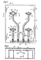
- the improved cooking hob according to the invention comprises a drip plate 1, which rests by its perimetral edge on the corresponding horizontal perimetral edge of a lower box casing 9, for containing the gas burners, conduits and taps as will be described hereinafter.
- Said drip plate 1, of usual shape, is traversed by e slight central depression which is slightly below the plane of said perimetral edge.
- the drip plate 1 is constructed from a thin sheet or stainless steel for the reasons which will be specified hereinafter.
- the drip plate 1 is traversed by a small transverse rib 10, the upper wall of which is slightly below the perimetral edge of the drip plate.
- a small transverse rib 10 In the depression in this latter, there are provided four circular drawn portions 11 standing in slight relief and of different diameter, for receiving four gas rings.
- a head 7 and a diffuser disc 8 are disposed on the upper wall of each drawn portion 11.
- the perimetral corner of the depression provided in the drip plate 1 receives the base bar of a normal grid 2, the upper bars of which are disposed above the said gas rings.
- a control panel 3 for receiving the operating knobs 4 for said gas rings and possibly other controls, and to the rear of which there is a raised portion 5, the purpose of which is to protect the controls on the panel 3 from the heat of the operating gas rings.
- FIG 1 also shows that suitable recesses 6 are provided in the vertical side edges of the box casing 9, and are described hereinafter.
- the base wall of the panel 3 is provided with a series of through bores 3a for traversing by the controls disposed on the panel 3.
- each recess 6 is provided with a through bore 23. From the same figure it can be seen that in proximity to the front edge of the box casing 9 there is a gas manifold 25 to which four taps 26 for the gas rings of said cooking hob are connected.
- the manifold 25 emerges from the box casing 9, but without extending beyond its transverse limits, in order to receive a connector 27 for connection to the domestic gas system.
- this connector 27 is housed in a suitable recessed seat provided et the front right hand corner of the box casing 9.
- each venturi mixer tube 266 which extends into a conduit 24 which feeds the corresponding burner.
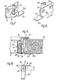
- the vertical side wall of each recess 6 is provided with two rectangular apertures 29 above a circular centering bore 28.
- Figure 4 also shows that the apertures 29 are symmetrical about the axis of symmetry of said recess, and the centering bore 28 lies on said axis of symmetry.
- each gas conduit 24 is inserted into the corresponding burner 18 which, as shown in Figure 6, is configured in the manner of a smoker's pipe so as to have an extremely small vertical dimension.
- Said burner head 7 is externally of cone frustum shape, and is provided internally with a cylindrical seat provided at its base with a circumferential rib, and a set of three flared through bores (Figure 6).
- Each burner 18 is provided on its outside below the centering ribs 18s with a perimetral flange 19 which when viewed in plan, as shown in Figure 3, is of polygonal shape.
- the upper face of the flange 19 is provided with a slight groove into which a suitable gasket 20 is inserted.
- This gasket which is of asbestos or another equivalent insulating material, has a thickness slightly greater than the depth of the corresponding groove provided in the flange 19.
- the lower face of the corresponding drawn portion 11 rests on the upper face of this insulating gasket 20 such that the sheet metal forming the drip plate 1 is slightly spaced apart from the horizontal perimetral edge of the flange 19.
- said flange 19 is provided with a set of three threaded bores 22 (Fig. 3).
- the lower face of the base of the inner cylindrical seat of each head 7 of the burners has a configuration which when viewed in plan practically coincides with the configuration of the corresponding flange 19 of the burner 18. Consequently, the lower face of said head 7 of the corresponding burner is provided with a groove into which a further gasket 20 is inserted.
- This latter of asbestos or another equivalent material, has a thickness slightly greater than the depth of the groove in the inner circumferential rib of the head 7, such that this latter is displaced slightly from the upper face of the drawn portion 11.
- This pair of gaskets 20 is provided with a set of three through bores which, when the gas ring is mounted, are aligned with the corresponding three flared bores in the flat base of the head 7, with the three through bores 12 in the drawn portion 11, and with the three threaded bores 22 provided in the corresponding flange 19.
- said elements 7, 1 and 19 are rigidly connected together by a suitable set of flared head tightening screws 21.
- the inner diameter of the circumferential rib of the head 7 is slightly greater than the outer diameter of the mouth of the corresponding pipe burner 18.
- the through bore 12a in the corresponding drawn portion 11 has a diameter slightly greater than the outer diameter of the burner mouth 18.
- Two horizontal appendices 17 branch from the outer lower regions of each burner 18, and are disposed substantially symmetrical about the longitudinal plane of symmetry of the burner 18.
- the free ends of these appendices 17 are embedded in an insulating block 16 of ceramic or another equivalent material, fixed by a pair of bolts 15 to the base wall of the box casing 9.
- this quick coupling device consists essentially of a U bracket 31, the base wall of which is provided with two hooks 32 facing downwards for insertion into the apertures 6, and a centering stem 33 for insertion into the corresponding centering bore 28 in the inner wall of the corresponding recess 6. Consequently, even though not previously stated, said hooks 32 and stem 33 lie on the outer face of the base well of the bracket 31.
- a threaded pin 34 is rotatably mounted through the arms of the bracket 31, and is provided with two opposing heads disposed on the outside of said arms of the bracket 31.
- each of these heads is provided with a diametrical slot for receiving the blade of a screwdriver.
- the central part of the threaded pin 34 is screwed through a profiled tooth 35 of step shape.
- the free end of the profiled tooth 35 comprises a non-slip lip 35a.
- the profiled tooth 35 is constructed by bending a metal plate which has one corner 36 rounded on the horizontal portion of the profiled tooth 35. Said rounded corner 36 is disposed to the rear for clockwise rotation of the threaded pin 34, this direction of rotation causing the pin 34 to screw into the profiled tooth 35 so as to pull it upwards.
- the lower arm of the bracket 31 is shaped such that during anti-clockwise rotation of the threaded pin 34, the profiled tooth 35 rests against the base wall of the bracket 31 so that it completely lies within the transverse dimensional limits of said bracket 31.
- the profiled tooth 35 in said position the profiled tooth 35 is completely housed, together with the corresponding bracket 31, within the recess 6 so that it in no way impedes the insertion of the cooking hob 9 into the corresponding aperture provided in the top 30 of a normal kitchen cabinet.
- the thickness of that part of the cooking hob lying below its perimetral edge which rests on the housing top 30 is extremely small, of the order of 3 cm, because of which the cooking hob can be built into the top of any kitchen cabinet.
- This small thickness is made possible by the rigidity and consistency of the entire cooking hob according to the invention.
- the cooking hob according to the invention can be built into the top of a normal cabinet designed for containing foodstuffs or kitchen utensils, and, more advantageously, can be built into the top of those cabinet housings for containing domestic appliances such as a dishwasher, washing machine or a small refrigerator.
- the box casing 9 is prevented from attaining a temperature exceeding 60°C, which could be damaging to machines which are fitted closely below the top 30.
- the rational coupling devices with which the cooking hob according to the invention are equipped enable this latter to be quickly and easily fixed to the top 30 of the corresponding cabinet, after the top 30 has been provided with a suitable aperture for receiving the bottom of the cooking hob.
- these coupling devices can be operated either from above or from below, but obviously operation from above is always more simple and rapid. This operation from above is particularly advantageous when the cooking hob is to be built into the top 30 of a cabinet for housing a domestic appliance which, as normally happens in the known art, occupies practically the whole of the interior of said cabinet.
- the great advantages of such coupling devices become extremely important when the cooking hob has to be dismantled and remounted for overhaul, adjustment and/or replacement of faulty or damaged members.
- the cooking hob according to the invention is built into the corresponding aperture in the top 30 of a normal kitchen cabinet in the following manner.
- the screws 21 are firstly removed in order to separate the drip plate 1 from the box casing 9.
- the threaded pins 34 are rotated with a screwdriver through the through bores 23 in the box casing 9, so that the profiled teeth 35 are brought into contact with the base wall of the corresponding bracket 31.
- the profiled teeth 35 are made to lie within the lateral dimensional limits of the box casing 9, so that this latter can be easily inserted into the aperture in the top 30, against which the box casing 9 rests by way of the resilient perimetral gasket 13.
- the cooking hob is dismantled by a procedure substantially the reverse of that heretofore described.
Landscapes
- Engineering & Computer Science (AREA)
- Chemical & Material Sciences (AREA)
- Combustion & Propulsion (AREA)
- Mechanical Engineering (AREA)
- General Engineering & Computer Science (AREA)
- Baking, Grill, Roasting (AREA)
- Combinations Of Kitchen Furniture (AREA)
Applications Claiming Priority (2)
| Application Number | Priority Date | Filing Date | Title |
|---|---|---|---|
| IT4681579 | 1979-02-02 | ||
| IT46815/79A IT1125102B (it) | 1979-02-02 | 1979-02-02 | Piano di cottura perfezionato particolarmente per montaggi del tipo ad incasso |
Publications (3)
| Publication Number | Publication Date |
|---|---|
| EP0014487A2 true EP0014487A2 (fr) | 1980-08-20 |
| EP0014487A3 EP0014487A3 (en) | 1980-09-17 |
| EP0014487B1 EP0014487B1 (fr) | 1983-05-25 |
Family
ID=11259084
Family Applications (1)
| Application Number | Title | Priority Date | Filing Date |
|---|---|---|---|
| EP80200025A Expired EP0014487B1 (fr) | 1979-02-02 | 1980-01-11 | Plaque de cuisson encastrable |
Country Status (10)
| Country | Link |
|---|---|
| US (1) | US4354478A (fr) |
| EP (1) | EP0014487B1 (fr) |
| AU (1) | AU526092B2 (fr) |
| CA (1) | CA1119068A (fr) |
| DE (1) | DE3063385D1 (fr) |
| ES (1) | ES244512Y (fr) |
| GB (1) | GB2044440B (fr) |
| IT (1) | IT1125102B (fr) |
| NZ (1) | NZ192621A (fr) |
| PT (1) | PT70756A (fr) |
Cited By (5)
| Publication number | Priority date | Publication date | Assignee | Title |
|---|---|---|---|---|
| EP0019231A1 (fr) * | 1979-05-16 | 1980-11-26 | COMPAGNIE EUROPEENNE POUR L'EQUIPEMENT MENAGER "CEPEM" Société anonyme dite: | Brûleur à gaz |
| FR2508142A1 (fr) * | 1981-06-23 | 1982-12-24 | Bosch Siemens Hausgeraete | Table de cuisson encastrable |
| DE102005026212A1 (de) * | 2005-06-07 | 2006-12-14 | BSH Bosch und Siemens Hausgeräte GmbH | Kochmulde |
| EP2292978B1 (fr) * | 2009-09-03 | 2015-01-28 | BSH Bosch und Siemens Hausgeräte GmbH | Table de cuisson, notamment table de cuisson au gaz et procédé de montage d'une table de cuisson |
| EP2295867A3 (fr) * | 2009-09-09 | 2017-12-06 | BSH Hausgeräte GmbH | Plaque de cuisson à gaz et cuisinière à gaz dotée d'une plaque de cuisson à gaz correspondante |
Families Citing this family (18)
| Publication number | Priority date | Publication date | Assignee | Title |
|---|---|---|---|---|
| GB2164742B (en) * | 1984-09-17 | 1988-02-10 | Ti New World Ltd | Improvements in or relating to hobs |
| GB8517785D0 (en) * | 1985-07-15 | 1985-08-21 | Ti New World Ltd | Hobs |
| GB8531447D0 (en) * | 1985-12-20 | 1986-02-05 | Cannon Ind Ltd | Gas hotplates |
| DE3703223A1 (de) * | 1987-02-04 | 1988-08-18 | Buderus Kuechentechnik | Einbauherd |
| US5323759A (en) * | 1993-06-11 | 1994-06-28 | Peerless Premier Appliance Company | Sealed burner mounting assembly |
| US5628302A (en) * | 1995-06-21 | 1997-05-13 | Maytag Corporation | Burner assembly and pan seal |
| IT1283735B1 (it) * | 1996-04-12 | 1998-04-30 | Whirlpool Europ S R L | Bruciatore a gas di semplice connessione alla struttura del piano di cottura ed al condotto di alimentazione del gas |
| GB2325047B (en) * | 1997-05-09 | 2000-01-12 | Creda Ltd | A gas hob |
| IT1315613B1 (it) * | 2000-03-10 | 2003-03-14 | Grandi Angelo Cucine Spa | Piano di cottura con bruciatori a gas per apparecchiature adibite allacottura di alimenti. |
| USD473096S1 (en) | 2001-07-09 | 2003-04-15 | Whirlpool Corporation | Cooktop |
| MY144257A (en) * | 2004-10-28 | 2011-08-29 | Electrolux Ab | Improved cooking gas burner |
| KR100936155B1 (ko) * | 2007-12-05 | 2010-01-12 | 엘지전자 주식회사 | 노즐어셈블리 및 이를 포함하는 조리기기 |
| DE102009001854A1 (de) | 2009-03-25 | 2010-09-30 | BSH Bosch und Siemens Hausgeräte GmbH | Gaskochmulde |
| ES2381485B1 (es) * | 2009-04-17 | 2013-05-03 | BSH Electrodomésticos España S.A. | Campo de coccion, en especial campo de coccion a gas. |
| NL2003212C2 (nl) * | 2009-07-16 | 2011-01-18 | Rvs Werken B V | Brandermodule voor een fornuis, een fornuis en werkwijze voor het vervaardigen daarvan. |
| US9784454B2 (en) * | 2013-03-14 | 2017-10-10 | Whirlpool Corporation | Cooktop burner mounting system |
| NL2014954B1 (nl) * | 2014-11-28 | 2016-10-11 | Pcs Holding B V | Brandermodule voorzien van hitteschild en bus, fornuis of kookplaat voorzien daarvan en werkwijze voor het vervaardigen daarvan. |
| US11747020B2 (en) * | 2021-08-11 | 2023-09-05 | Haier Us Appliance Solutions, Inc. | Cooktop and insulated burner assembly |
Family Cites Families (12)
| Publication number | Priority date | Publication date | Assignee | Title |
|---|---|---|---|---|
| US1187664A (en) * | 1915-10-28 | 1916-06-20 | Hirsch Herbert Sichel | Automobile heater attachment. |
| US1648789A (en) * | 1926-10-04 | 1927-11-08 | American Stove Co | Gas range and burner therefor |
| US1986017A (en) * | 1931-12-11 | 1935-01-01 | Floyd Wells Company | Combined rack, drip pan, baffle, and lighter for ranges |
| US2107972A (en) * | 1936-08-29 | 1938-02-08 | Roberts & Mander Stove Company | Cooking stove |
| US3015329A (en) * | 1955-02-21 | 1962-01-02 | Chambers Corp | Burner box for top burner unit |
| US2887103A (en) * | 1955-12-15 | 1959-05-19 | Roper Corp Geo D | Countertop cooking unit and mounting therefor |
| US2915960A (en) * | 1958-06-13 | 1959-12-08 | Jr Harry R Mcclellan | Wall-mounted indoor or outdoor cooking fireplace |
| US3130719A (en) * | 1960-02-03 | 1964-04-28 | Tappan Co | Gas range |
| US3701171A (en) * | 1969-06-24 | 1972-10-31 | Gen Electric | Work surface clamping means for drop-in cooking equipment |
| FR2219716A5 (fr) * | 1973-02-26 | 1974-09-20 | Parkinson Cowan Appliances Ltd | |
| DE7809548U1 (de) * | 1978-03-31 | 1979-09-06 | Blanc Gmbh & Co, 7519 Oberderdingen | Gasbrenner |
| FR2424479A1 (fr) * | 1978-04-28 | 1979-11-23 | Rosieres Usines | Tables de cuisson encastrables fonctionnant au gaz et a l'electricite, modulaires et extra-plates |
-
1979
- 1979-02-02 IT IT46815/79A patent/IT1125102B/it active
- 1979-06-26 ES ES1979244512U patent/ES244512Y/es not_active Expired
-
1980
- 1980-01-11 DE DE8080200025T patent/DE3063385D1/de not_active Expired
- 1980-01-11 EP EP80200025A patent/EP0014487B1/fr not_active Expired
- 1980-01-14 US US06/111,803 patent/US4354478A/en not_active Expired - Lifetime
- 1980-01-15 NZ NZ192621A patent/NZ192621A/xx unknown
- 1980-01-21 AU AU54750/80A patent/AU526092B2/en not_active Ceased
- 1980-01-30 GB GB8003141A patent/GB2044440B/en not_active Expired
- 1980-01-30 PT PT70756A patent/PT70756A/pt unknown
- 1980-01-30 CA CA000344673A patent/CA1119068A/fr not_active Expired
Cited By (5)
| Publication number | Priority date | Publication date | Assignee | Title |
|---|---|---|---|---|
| EP0019231A1 (fr) * | 1979-05-16 | 1980-11-26 | COMPAGNIE EUROPEENNE POUR L'EQUIPEMENT MENAGER "CEPEM" Société anonyme dite: | Brûleur à gaz |
| FR2508142A1 (fr) * | 1981-06-23 | 1982-12-24 | Bosch Siemens Hausgeraete | Table de cuisson encastrable |
| DE102005026212A1 (de) * | 2005-06-07 | 2006-12-14 | BSH Bosch und Siemens Hausgeräte GmbH | Kochmulde |
| EP2292978B1 (fr) * | 2009-09-03 | 2015-01-28 | BSH Bosch und Siemens Hausgeräte GmbH | Table de cuisson, notamment table de cuisson au gaz et procédé de montage d'une table de cuisson |
| EP2295867A3 (fr) * | 2009-09-09 | 2017-12-06 | BSH Hausgeräte GmbH | Plaque de cuisson à gaz et cuisinière à gaz dotée d'une plaque de cuisson à gaz correspondante |
Also Published As
| Publication number | Publication date |
|---|---|
| GB2044440B (en) | 1983-12-14 |
| CA1119068A (fr) | 1982-03-02 |
| DE3063385D1 (en) | 1983-07-07 |
| IT1125102B (it) | 1986-05-14 |
| NZ192621A (en) | 1983-04-12 |
| AU526092B2 (en) | 1982-12-16 |
| ES244512U (es) | 1979-11-01 |
| EP0014487A3 (en) | 1980-09-17 |
| EP0014487B1 (fr) | 1983-05-25 |
| PT70756A (en) | 1980-02-01 |
| IT7946815A0 (it) | 1979-02-02 |
| ES244512Y (es) | 1980-04-16 |
| GB2044440A (en) | 1980-10-15 |
| US4354478A (en) | 1982-10-19 |
| AU5475080A (en) | 1980-08-07 |
Similar Documents
| Publication | Publication Date | Title |
|---|---|---|
| US4354478A (en) | Cooking hob, particularly for built-in assembly | |
| US11187416B2 (en) | Gas cooktop and grate for the gas cooktop | |
| US6064042A (en) | Reversible self-contained cooking appliance | |
| US2417977A (en) | Cook stove and range | |
| US3008406A (en) | Cooking unit | |
| WO2021259303A1 (fr) | Capteur de température de dispositif de cuisinière ayant une fonction de correction de température instantanée | |
| US3706302A (en) | Continuous clean oven conversion | |
| EP1508001B1 (fr) | Assemblage pour gazinières comprenant un brûleur à gaz et un support pour récipient | |
| EP0505806B1 (fr) | Plaque de cuisson | |
| US20020092515A1 (en) | Device for supporting and locating a gas burner in a cooker | |
| US20220178550A1 (en) | Cooking appliance and knob assembly | |
| US20240255980A1 (en) | Systems for knob lockout on appliances | |
| JPS6122205B2 (fr) | ||
| JP3157052B2 (ja) | 給食用カセットフレーム | |
| US20240230106A1 (en) | Removable bracket assembly for an oven appliance manifold | |
| US3288130A (en) | Device for leveling pans | |
| CN219103078U (zh) | 燃气灶的锅具支架及燃气灶 | |
| RU2783592C1 (ru) | Улучшенная индукционная варочная система | |
| WO2025193207A1 (fr) | Système de verrouillage | |
| JPH0515879Y2 (fr) | ||
| EP2708815A2 (fr) | Un robinet de gaz pour tactiles systèmes de contrôle de gaz | |
| KR200359503Y1 (ko) | 취사설비용 가스센서 모듈 | |
| GB2159618A (en) | Built-in hob unit | |
| WO2025144244A1 (fr) | Système de montage pour étagère latérale et numérateur | |
| JPS5848970Y2 (ja) | 電気コンロ |
Legal Events
| Date | Code | Title | Description |
|---|---|---|---|
| PUAI | Public reference made under article 153(3) epc to a published international application that has entered the european phase |
Free format text: ORIGINAL CODE: 0009012 |
|
| PUAL | Search report despatched |
Free format text: ORIGINAL CODE: 0009013 |
|
| AK | Designated contracting states |
Designated state(s): BE CH DE FR LU NL SE |
|
| AK | Designated contracting states |
Designated state(s): BE CH DE FR LU NL SE |
|
| RAP1 | Party data changed (applicant data changed or rights of an application transferred) |
Owner name: SOCIETA PER AZIONI TECNOGAS FABBRICA APPARECCHIATU |
|
| 17P | Request for examination filed |
Effective date: 19810115 |
|
| GRAA | (expected) grant |
Free format text: ORIGINAL CODE: 0009210 |
|
| AK | Designated contracting states |
Designated state(s): BE CH DE FR LU NL SE |
|
| REF | Corresponds to: |
Ref document number: 3063385 Country of ref document: DE Date of ref document: 19830707 |
|
| ET | Fr: translation filed | ||
| PGFP | Annual fee paid to national office [announced via postgrant information from national office to epo] |
Ref country code: BE Payment date: 19831130 Year of fee payment: 5 |
|
| PGFP | Annual fee paid to national office [announced via postgrant information from national office to epo] |
Ref country code: FR Payment date: 19831205 Year of fee payment: 5 |
|
| PGFP | Annual fee paid to national office [announced via postgrant information from national office to epo] |
Ref country code: CH Payment date: 19831221 Year of fee payment: 5 |
|
| PGFP | Annual fee paid to national office [announced via postgrant information from national office to epo] |
Ref country code: DE Payment date: 19831222 Year of fee payment: 5 |
|
| PGFP | Annual fee paid to national office [announced via postgrant information from national office to epo] |
Ref country code: SE Payment date: 19831231 Year of fee payment: 5 |
|
| PGFP | Annual fee paid to national office [announced via postgrant information from national office to epo] |
Ref country code: LU Payment date: 19840104 Year of fee payment: 5 |
|
| PG25 | Lapsed in a contracting state [announced via postgrant information from national office to epo] |
Ref country code: LU Free format text: LAPSE BECAUSE OF NON-PAYMENT OF DUE FEES Effective date: 19840131 |
|
| PGFP | Annual fee paid to national office [announced via postgrant information from national office to epo] |
Ref country code: NL Payment date: 19840131 Year of fee payment: 5 |
|
| PLBE | No opposition filed within time limit |
Free format text: ORIGINAL CODE: 0009261 |
|
| STAA | Information on the status of an ep patent application or granted ep patent |
Free format text: STATUS: NO OPPOSITION FILED WITHIN TIME LIMIT |
|
| 26N | No opposition filed | ||
| PG25 | Lapsed in a contracting state [announced via postgrant information from national office to epo] |
Ref country code: SE Effective date: 19850112 |
|
| PG25 | Lapsed in a contracting state [announced via postgrant information from national office to epo] |
Ref country code: CH Effective date: 19850131 Ref country code: BE Effective date: 19850131 |
|
| BERE | Be: lapsed |
Owner name: S.P.A. TECNOGAS FABBRICA APPARECCHIATURE TERMO-ELE Effective date: 19850111 |
|
| PG25 | Lapsed in a contracting state [announced via postgrant information from national office to epo] |
Ref country code: NL Effective date: 19850801 |
|
| NLV4 | Nl: lapsed or anulled due to non-payment of the annual fee | ||
| PG25 | Lapsed in a contracting state [announced via postgrant information from national office to epo] |
Ref country code: FR Free format text: LAPSE BECAUSE OF NON-PAYMENT OF DUE FEES Effective date: 19850930 |
|
| REG | Reference to a national code |
Ref country code: CH Ref legal event code: PL |
|
| PG25 | Lapsed in a contracting state [announced via postgrant information from national office to epo] |
Ref country code: DE Effective date: 19851001 |
|
| REG | Reference to a national code |
Ref country code: FR Ref legal event code: ST |
|
| EUG | Se: european patent has lapsed |
Ref document number: 80200025.7 Effective date: 19860129 |