EP0014560A1 - Procédé et dispositif pour plier les fermetures d'extrémité de cartons - Google Patents
Procédé et dispositif pour plier les fermetures d'extrémité de cartons Download PDFInfo
- Publication number
- EP0014560A1 EP0014560A1 EP80300271A EP80300271A EP0014560A1 EP 0014560 A1 EP0014560 A1 EP 0014560A1 EP 80300271 A EP80300271 A EP 80300271A EP 80300271 A EP80300271 A EP 80300271A EP 0014560 A1 EP0014560 A1 EP 0014560A1
- Authority
- EP
- European Patent Office
- Prior art keywords
- carton
- gusset
- panel
- folding
- along
- Prior art date
- Legal status (The legal status is an assumption and is not a legal conclusion. Google has not performed a legal analysis and makes no representation as to the accuracy of the status listed.)
- Withdrawn
Links
- 238000000034 method Methods 0.000 title claims 5
- 239000002184 metal Substances 0.000 claims description 3
- 238000013459 approach Methods 0.000 claims 2
- 238000007789 sealing Methods 0.000 description 19
- 239000011094 fiberboard Substances 0.000 description 13
- 239000000463 material Substances 0.000 description 7
- 239000000758 substrate Substances 0.000 description 6
- 230000007246 mechanism Effects 0.000 description 5
- 235000019808 microcrystalline wax Nutrition 0.000 description 3
- 239000004200 microcrystalline wax Substances 0.000 description 3
- 239000004698 Polyethylene Substances 0.000 description 2
- 239000000853 adhesive Substances 0.000 description 2
- 230000001070 adhesive effect Effects 0.000 description 2
- 230000008901 benefit Effects 0.000 description 2
- 230000015572 biosynthetic process Effects 0.000 description 2
- 230000006835 compression Effects 0.000 description 2
- 238000007906 compression Methods 0.000 description 2
- 230000032798 delamination Effects 0.000 description 2
- 239000000945 filler Substances 0.000 description 2
- 238000003475 lamination Methods 0.000 description 2
- 239000000155 melt Substances 0.000 description 2
- 238000004806 packaging method and process Methods 0.000 description 2
- -1 polyethylene Polymers 0.000 description 2
- 229920000573 polyethylene Polymers 0.000 description 2
- 238000004826 seaming Methods 0.000 description 2
- 239000007787 solid Substances 0.000 description 2
- 230000001360 synchronised effect Effects 0.000 description 2
- 239000004831 Hot glue Substances 0.000 description 1
- 229920000271 Kevlar® Polymers 0.000 description 1
- 239000004809 Teflon Substances 0.000 description 1
- 229920006362 Teflon® Polymers 0.000 description 1
- 238000004026 adhesive bonding Methods 0.000 description 1
- 230000004888 barrier function Effects 0.000 description 1
- 230000008859 change Effects 0.000 description 1
- 238000005520 cutting process Methods 0.000 description 1
- 239000011152 fibreglass Substances 0.000 description 1
- 239000011888 foil Substances 0.000 description 1
- 239000012943 hotmelt Substances 0.000 description 1
- 239000004761 kevlar Substances 0.000 description 1
- 239000002655 kraft paper Substances 0.000 description 1
- 239000002648 laminated material Substances 0.000 description 1
- 238000010030 laminating Methods 0.000 description 1
- 239000007788 liquid Substances 0.000 description 1
- 229920001684 low density polyethylene Polymers 0.000 description 1
- 239000004702 low-density polyethylene Substances 0.000 description 1
- 238000004519 manufacturing process Methods 0.000 description 1
- 238000012986 modification Methods 0.000 description 1
- 230000004048 modification Effects 0.000 description 1
- 239000011087 paperboard Substances 0.000 description 1
- 230000000452 restraining effect Effects 0.000 description 1
- 238000000926 separation method Methods 0.000 description 1
- 229920003002 synthetic resin Polymers 0.000 description 1
- 239000000057 synthetic resin Substances 0.000 description 1
- 229920001169 thermoplastic Polymers 0.000 description 1
- 239000004416 thermosoftening plastic Substances 0.000 description 1
- 239000001993 wax Substances 0.000 description 1
Images


Classifications
-
- B—PERFORMING OPERATIONS; TRANSPORTING
- B65—CONVEYING; PACKING; STORING; HANDLING THIN OR FILAMENTARY MATERIAL
- B65B—MACHINES, APPARATUS OR DEVICES FOR, OR METHODS OF, PACKAGING ARTICLES OR MATERIALS; UNPACKING
- B65B7/00—Closing containers or receptacles after filling
- B65B7/16—Closing semi-rigid or rigid containers or receptacles not deformed by, or not taking-up shape of, contents, e.g. boxes or cartons
-
- B—PERFORMING OPERATIONS; TRANSPORTING
- B65—CONVEYING; PACKING; STORING; HANDLING THIN OR FILAMENTARY MATERIAL
- B65D—CONTAINERS FOR STORAGE OR TRANSPORT OF ARTICLES OR MATERIALS, e.g. BAGS, BARRELS, BOTTLES, BOXES, CANS, CARTONS, CRATES, DRUMS, JARS, TANKS, HOPPERS, FORWARDING CONTAINERS; ACCESSORIES, CLOSURES, OR FITTINGS THEREFOR; PACKAGING ELEMENTS; PACKAGES
- B65D5/00—Rigid or semi-rigid containers of polygonal cross-section, e.g. boxes, cartons or trays, formed by folding or erecting one or more blanks made of paper
- B65D5/02—Rigid or semi-rigid containers of polygonal cross-section, e.g. boxes, cartons or trays, formed by folding or erecting one or more blanks made of paper by folding or erecting a single blank to form a tubular body with or without subsequent folding operations, or the addition of separate elements, to close the ends of the body
- B65D5/0227—Rigid or semi-rigid containers of polygonal cross-section, e.g. boxes, cartons or trays, formed by folding or erecting one or more blanks made of paper by folding or erecting a single blank to form a tubular body with or without subsequent folding operations, or the addition of separate elements, to close the ends of the body with end closures formed by inward folding of flaps and securing them by heat-sealing, by applying adhesive to the flaps or by staples
Definitions
- This invention relates to packaging and more specifically to apparatus for folding the end closures of cartons of the type which include a pair of gusset closure panels.
- the package is formed from a laminated blank wherein a moisture-resistant film material having heat-sealing characteristics, such as polyethylene film, is adhered to a fiberboard substrate by a heat-weakenable laminant, such as microcrystalline wax.
- the blank may be formed by die-cutting sheets or rolls of such a lamination so that the two layers will be substantially coextensive.
- portions or panels of the fiberboard substrate are separated from the inner lining by selective heat delamination.
- Apparatus for closing and sealing the ends of packages of this general type which is illustrated in the aforementioned U.S. patent, takes the form of a pair of synchronized, intermittently rotating turrets, each of which has a plurality of pocket members into which individual cartons are received. More versatile apparatus for closing and sealing such packages has been found desirable.
- One advantage lies in being able to run the conveyor continuously, as opposed to intermittently, which itself is conducive to higher speed operation, and another lies in the versatility of operation.
- the present invention provides apparatus for automatically carrying out such a folding operation.
- FIGURES 1 through 6 A typical gusseted carton of the general type which the present invention is designed to manipulate is depicted in FIGURES 1 through 6.
- the carton is formed from a single blank of laminated material, namely, a fiberboard substrate to which polyethylene sheeting is adhered by a thin layer of heat-flowable material, such as microcrystalline wax.
- the fiberbroad substrate may be of any reasonable density and thickness, for example, 40 pound bleached kraft board.
- the sheeting may be ac thin as 2 mil low density polyethylene film, or a suitable lamination of foil and one or more synthetic resin materials may be used so long as the exposed surface is a heat-sealable material.
- the laminating material is preferably a microcrystalline wax or some other suitable material which melts at a temperature below the heat-sealing temperature of the thermoplastic surface of the sheeting. Accordingly, as pointed out in the aforementioned patent, during heat-sealing operation, the wax melts.and is absorbed into the relatively porous fiberboard surface, thus selectively delaminating the fiberboard substrate from the film liner in the particular region.
- the flat blank is formed into a flat-folded tube which, when opened, has a rectangular cross section.
- the carton has four sidewalls which are referred to, for reference purposes, as a front wall 11, a rear wall 13 and a pair of lateral walls 15,17.
- the end closure is formed by panels which are extensions of these sidewalls and which are hinged to the upper edges thereof.
- a similar end closure is preferably provided at the bottom of the carton; however, a different type of end closure could be used if desired for some reason.
- the end closure includes a major or cover panel 19 which is hinged to the rear wall 13 of the carton and which is of a sufficient size to completely cover the entire opening.
- a pair of gusset panels 21,23 are provided at the top of each of the lateral sidewalls 15,17 one edge of which is hinged thereto whereas the other edge of which is hinged to a lateral edge cf the cover panel 19.
- These gusset panels 21,23 are provided, respectively, with a crease or fold line 21a,23a which extends at a 45° angle from the edge along which the gusset is hinged to the underlying sidewall.
- a flange panel 25 is attached to the free edge of the cover panel 19, and short flange extensions 27,28 are hinged to the upper edges of the gusset panels 21,23.
- a short flap 29 is hinged to the upper edge of the front wall 11: however, the adjacent edges between the front flap 29 and the gusset panels 21,23 are only partially severed so that the substrate or fiberboard layer is weakened but the sheeting is not cut.
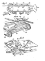
- FIG. 7 Overall apparatus is diagrammatically illustrated in FIG. 7 for automatically removing the flat-folded carton blanks from a stack in a magazine and forming, filling and sealing them into completed packages. Described in detail hereinafter is the portion of the apparatus for completing the manipulation of the upper end closure. It should be understood that the same mechanisms are employed to initially manipulate, seal and close the bottom end closure; however, inasmuch as the mechanism for operating . on the upper end closure is easier to illustrate, it was chosen.
- the cartons are carried by an endless chain conveyor 31 which carries a series of U-shaped pocket members 33, each of which is proportioned to receive a single carton.
- the conveyor 31 includes a heavy roller chain to which each pocket member 33 is linked by a suitable bracket and which is continuously driven at a constant speed so that the pocket members 33 move along an endless path.
- An infeed device 35 and a take-off device 37 are located adjacent one end of the conveyor 31 where the chains change direction at a rotary end section. There are two essentially straight run sections which extend between the rotary ends. The folding of the bottom end closure is effected by mechanism 39 located at the beginning of the first straight run section.
- the bottom of the inner liner is then totally heat-sealed by a bottom sealer 41 which also delaminates the lower end closure sheeting panels from selected of the fiberboard panels. Thereafter, the outer fiberboard end closure panels are folded by a bottom-closing mechanism 43. Next, the contents are supplied, via a rotary filler 45, through the open upper end of the carton as it travels around the other rotary end section of the conveyor.
- the product being filled can be a solid, a semi-solid or even a liquid. Following'filling, the upper end closure is closed and sealed in a manner essentially the same as the bottom end closure.
- the cartons leaving the rotary filler section enter a top folder 47 where the front flap 29 is first plowed outward, and then the gusset panels are outfolded along the fold lines 21a and 23a, as depicted in FIG. 2 Simultaneously with the outfolding, the cover panel 19 is plowed downward so that it completely closes the upper end opening, and heat-sealing is effected in this configuration, as depicted in FIG. 3, by a top sealer 49.
- the cover panel 19, the adjacent gusset panels 21,23, the flange panels 25,27,28 and the front flap 29 are held pressed together by means of a heat-conductive belt that moves along above the pocket members 33 at exactly the same speed as the conveyor 31.
- Suitable heaters are disposed adjacent the opposite, upper surface of the belt which supply the heat for the heat-sealing and delamination.
- the belt is preferably made of a material, such as Teflon-coated Fiberglass, Kevlar or metal, which exhibits good strength and excellent heat transfer properties.
- the carton When the carton leaves the heat-sealing section 47 and is no longer held down by the belt, the inherent resiliency of the fiberboard causes the cover and the gusset panels 21,23 to tend to spring slightly upward and separate from the now delaminated sheeting which forms the inner liner. It is in this general configuration that the carton enters the top infolding and closing section 51 of the apparatus. As the cartons are moved along by the U-shaped pockets 33 on the conveyor, they generally slide along a lower rail 53 (FIG.13) and are prevented from leaving the pockets by a restraining bar 55 along which the rear wall 13 of the carton generally rides.
- a main plow 57 is located which includes an inclined section 59 which lifts the front flap 29 and an adjacent edge 61 which turns it 180° through the vertical to the inturned position depicted in FIG. 4. It also includes a short triangular plow 63 which engages the undersurface of the front flange 25 and cams the cover panel 19 upward sufficiently far to complete the separation of the cover panel and the upper portions of the adjacent gusset panels from the sheeting from which they were delaminated. An extension 65 from the triangular plow 63 extends along the path of movement and holds the cover in the raised position, depicted in FIG. 4, until such time as the leading gusset 21 has been infolded.
- abutment 67 Disposed slightly further downstream along the path of movement from the triangular plow 63 is an abutment 67 which is positioned to engage the leading gusset panel 21 and fold it inwardly on the fold line 21a in the manner shown in FIG. 5.
- the abutment 67 is formed by a right angle section of a metal rod 69 which is attached to a bracket that is screwed to the main plow 57 generally adjacent the triangular plow. Downstream of the section which forms the abutment, the rod 69 continues and is bent to form a retainer section 71 which is curved and which holds the leading gusset panel 21 in the infolded configuration as the carton is carried along the conveyor 31.
- a separate unit 75 for infolding the trailing gusset panel 23 is located adjacent the main conveyor 31.
- This unit 75 includes a plurality of infolding heads 77 each of which is mounted on a separate individual carriage 79 that is fastened to an auxiliary conveyor.8l.
- the auxiliary unit 75 is suitably bolted to the main conveyor frame and includes front and rear, parallel roller chains 83 which are entrained about a pair of drive sprockets attached to a horizontal drive shaft 85 and a pair of idler sprockets carried by a spaced shaft 87.
- the unit 75 may contain any number of infolding heads, for example, four, which are individually spaced apart the same distance as there is between the U-shaped pockets 33 on the main conveyor 31, and the auxiliary chain conveyor 81 is driven at the same speed as the main conveyor which it parallels.
- the movement of the two parallel conveyors is of course synchronized so that, as the carriages 79 move from the lower reach to the upper reach of the auxiliary conveyor 81, they are each respectively aligned with one of the U-shaped pockets 33 that is carrying a filled and sealed carton.
- the carriage 79 then translates toward and moves along the main conveyor for a short distance during which the infolding of the trailing gusset panel 23 occurs.
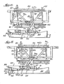
- the carriage 79 is slidably mounted on a pair of parallel rods 89, the ends of which are suitably attached to the front'and rear roller chains 83. Sliding movement of the carriage 79 along the rods 89 is effected by an underlying cam follower 91 which moves in a groove or track 93 provided in a flat cam plate 95 that is a stationary part of the auxiliary unit.
- Each folding head 77 contains a pair of flat spring fingers.97 which slide into overlying relationship with the front edge of the carton and which hold the front flap 29 in the inturned position whither it has been plowed by the edge 61 of the main plow 57. These spring fingers 97 slide over the upper fiberboard surface of the front flap 29 and press it downward against the just-sealed inner liner.
- the cam track 93 is best seen in FIGS. 10 and 11. Outward movement of the carriage 79 and the folding head 77 occurs quickly as the cam follower 91 moves along the initial angled section 93a of the track. Thereafter, the cam track has a short straight section 93b where the folding head 77 moves along with the U-shaped pocket 33 with the spring fingers 97 disposed in overlying position.
- the head 77 carries a movable arm 99 that forms one end of a bell crank 101 which is mounted at a pivot point 103 on the upper surface of the infolding head.
- a cam follower or roller 105 extends upward from the other end of the bell crank 101, and it moves into engagement with the edge of an adjustable cam 107 that is supported on a slotted mounting bar 109 which overlies the infolding unit 75.
- a bolt allows precise positioning of the cam 107 along the slot to obtain the precise timed swinging movement of the arm 99.
- Fig. 11 shows the upstanding roller 105 just beginning to engage the edge of the overlying adjustable cam 107, and further movement of the head 77 causes the bell crank 101 to pivot counterclockwise, as viewed from above.
- the end of the arm 99 swings from a location just behind the trailing gusset to a more forward location (relative to the direction of conveyor movement) causing its edge to infold the narrower, trailing gusset flap 23.
- the head 77 preferably includes an overlying guide 111 under which' the arm portion 99 of the bell crank swings.
- the guide 111 assures that the free end of the arm 99 does not slip past the edge of the gusset 23.
- the relative narrowness of the trailing gusset 23 allows it to be carried past the right angle portion 67 of the rod (which serves as the abutment that infolds the leading gusset 21) without making contact with it.
- An overlying plow 115 is mounted on the main conveyor frame spaced slightly above the bar 55 and extends along the path of movement beginning at a location generally centrally of the infolding unit 75.
- the plow 115 extends over the path which the cartons take and folds the cover panel downward in cooperation with the infolding.
- the plow location is such that the leading gusset panel 21 has been infolded by the abutment 67 and is being held in the infolded position by the retainer portion of the rod 69 when contact is made between the arcuate edge of the plow 115 and the outer surface of the cover panel 19.
- the roller 105 reaches a curved section of the adjustable cam 107 which allows the bell crank 101 to swing back to its at-rest position.
- the bell crank 101 is suitably biased in this counterclockwise direction, as viewed from above, as by a spring (not shown) disposed about its pivot point 103 and a suitable stopper is provided, such as a peg 117 which extends upward from the surface of the head 77.
- the main cam follower 91 enters the angled return section 93c of the cam track causing the underlying carriage 79 to be drawn rearward, sliding along the pair of rods 89 and withdrawing the infolding head 77 from its association with the U-shaped pocket 33.
- the spring-fingers 97 slide out of contact with the front flap 29, and by this time, the.cover panel 19 has been plowed downward sufficiently so that the leading edge of it is beginning to make contact with the upper surface of the flap 29.
- the carton has been filled and sealed, and the top and bottom fiberboard portions of the end closures have been folded into their completed condition.
- final gluing could be effected at this time by extending the length of the machine, preferably the cartons are discharged into a suitable take-off device 37 which inserts them to a separate carton-gluer that applies a pattern of adhesive, for example hot melt, along the top and bottom edges of the front panel 11 and then plows the flange panels 25 into contact with the adhesive-coated front panel.
- a compression section of sufficient length holds these panels in contact with each other as the hot-melt adhesive quickly sets, and the fabrication of the package is complete when it leaves the compression section.
- the invention provides an efficient infolding mechanism for manipulating the gusset panels of a continuously moving carton having an end closure of this general design.
Landscapes
- Engineering & Computer Science (AREA)
- Mechanical Engineering (AREA)
- Making Paper Articles (AREA)
- Closing Of Containers (AREA)
Applications Claiming Priority (2)
| Application Number | Priority Date | Filing Date | Title |
|---|---|---|---|
| US06/009,515 US4251978A (en) | 1979-02-05 | 1979-02-05 | Carton closure infolder |
| US9515 | 1993-01-27 |
Publications (1)
| Publication Number | Publication Date |
|---|---|
| EP0014560A1 true EP0014560A1 (fr) | 1980-08-20 |
Family
ID=21738124
Family Applications (1)
| Application Number | Title | Priority Date | Filing Date |
|---|---|---|---|
| EP80300271A Withdrawn EP0014560A1 (fr) | 1979-02-05 | 1980-01-30 | Procédé et dispositif pour plier les fermetures d'extrémité de cartons |
Country Status (5)
| Country | Link |
|---|---|
| US (1) | US4251978A (fr) |
| EP (1) | EP0014560A1 (fr) |
| JP (1) | JPS55116509A (fr) |
| AU (1) | AU5510580A (fr) |
| CA (1) | CA1127437A (fr) |
Cited By (1)
| Publication number | Priority date | Publication date | Assignee | Title |
|---|---|---|---|---|
| EP2039612A1 (fr) | 2007-09-21 | 2009-03-25 | Fraunhofer-Gesellschaft zur Förderung der Angewandten Forschung e.V. | Boîte pliante imperméable à la poussière et aux insectes dotée d'une fermeture de sécurité circonférentielle |
Families Citing this family (8)
| Publication number | Priority date | Publication date | Assignee | Title |
|---|---|---|---|---|
| US4589246A (en) * | 1985-01-28 | 1986-05-20 | The Mead Corporation | Method of closing an end loading carton |
| US4627217A (en) * | 1985-08-20 | 1986-12-09 | Frito-Lay, Inc. | Apparatus for automatically closing L-slide lock cases |
| US4805375A (en) * | 1987-12-16 | 1989-02-21 | H. J. Langen & Sons Limited | Carton end closure |
| TW221401B (en) * | 1993-03-01 | 1994-03-01 | Riverwood Int Corp | Stacked article cartoning apparatus |
| ZA947021B (en) * | 1993-09-17 | 1995-05-02 | Riverwood Int Corp | Method of forming a stacked article group |
| ITBO20030503A1 (it) * | 2003-08-29 | 2005-02-28 | Gima Spa | Apparecchiatura per il confezionamento di un prodotto in un contenitore scatolare. |
| TWD174665S (zh) * | 2015-10-20 | 2016-04-01 | 台灣福興工業股份有限公司 | 包裝盒之部分 |
| TWD177735S (zh) * | 2015-10-20 | 2016-08-21 | 台灣福興工業股份有限公司 | 包裝盒之部分 |
Citations (1)
| Publication number | Priority date | Publication date | Assignee | Title |
|---|---|---|---|---|
| US4046308A (en) * | 1971-03-24 | 1977-09-06 | Paxall, Inc. | Packaging |
Family Cites Families (5)
| Publication number | Priority date | Publication date | Assignee | Title |
|---|---|---|---|---|
| US1948657A (en) * | 1930-07-23 | 1934-02-27 | Jl Ferguson Co | Liner folding device |
| US2391708A (en) * | 1943-06-26 | 1945-12-25 | Quaker Oats Co | Carton closing device |
| US2485235A (en) * | 1945-08-17 | 1949-10-18 | Container Corp | Method and apparatus for closing and sealing cartons |
| US2677220A (en) * | 1950-12-23 | 1954-05-04 | Gen Mills Inc | Method and mechanism for folding carton flaps |
| US4063403A (en) * | 1976-08-23 | 1977-12-20 | Bergstein Packaging Trust | Carton closing and sealing apparatus |
-
1979
- 1979-02-05 US US06/009,515 patent/US4251978A/en not_active Expired - Lifetime
-
1980
- 1980-01-29 CA CA344,606A patent/CA1127437A/fr not_active Expired
- 1980-01-30 EP EP80300271A patent/EP0014560A1/fr not_active Withdrawn
- 1980-01-31 AU AU55105/80A patent/AU5510580A/en not_active Abandoned
- 1980-02-05 JP JP1295280A patent/JPS55116509A/ja active Pending
Patent Citations (1)
| Publication number | Priority date | Publication date | Assignee | Title |
|---|---|---|---|---|
| US4046308A (en) * | 1971-03-24 | 1977-09-06 | Paxall, Inc. | Packaging |
Cited By (2)
| Publication number | Priority date | Publication date | Assignee | Title |
|---|---|---|---|---|
| EP2039612A1 (fr) | 2007-09-21 | 2009-03-25 | Fraunhofer-Gesellschaft zur Förderung der Angewandten Forschung e.V. | Boîte pliante imperméable à la poussière et aux insectes dotée d'une fermeture de sécurité circonférentielle |
| DE102007045233A1 (de) * | 2007-09-21 | 2009-04-02 | Fraunhofer-Gesellschaft zur Förderung der angewandten Forschung e.V. | Staub- und insektendichte Faltschachtel mit Rundum-Sicherheitsverschluss |
Also Published As
| Publication number | Publication date |
|---|---|
| US4251978A (en) | 1981-02-24 |
| AU5510580A (en) | 1980-08-14 |
| JPS55116509A (en) | 1980-09-08 |
| CA1127437A (fr) | 1982-07-13 |
Similar Documents
| Publication | Publication Date | Title |
|---|---|---|
| US5116322A (en) | Method and apparatus for gluing closure flaps of a carton on a continuously moving conveyor | |
| US3817017A (en) | Bag construction and method for filling the same | |
| US2485235A (en) | Method and apparatus for closing and sealing cartons | |
| US2206761A (en) | Machine and method for package closure | |
| US4056046A (en) | Apparatus for folding and gluing carton blanks | |
| US4251978A (en) | Carton closure infolder | |
| US4435944A (en) | Apparatus for orderly transport and storage of flat objects | |
| US3577699A (en) | Method of cartoning | |
| US5095960A (en) | Apparatus for filling bags with bulk material | |
| US3041806A (en) | Machine for forming lined packages | |
| US4206579A (en) | Carton closure outfolder | |
| US4046308A (en) | Packaging | |
| US3442063A (en) | Machine for closing cartons | |
| US2979995A (en) | Apparatus for closing and sealing lined containers | |
| US4023330A (en) | Wrapping machines | |
| US4063403A (en) | Carton closing and sealing apparatus | |
| US2773435A (en) | Continuously operating apparatus for making bags | |
| US2100739A (en) | Container machine | |
| US4189986A (en) | Method and apparatus for heat sealing a package blank | |
| US2972215A (en) | Packing apparatus | |
| US3313089A (en) | Bag closing machine | |
| US3451194A (en) | Flap folding means for packaging apparatus | |
| US3124915A (en) | Method of forming a lined carton | |
| US5983605A (en) | Machine and process for packing smoking articles | |
| US3085374A (en) | Method of and apparatus for forming and filling cartons |
Legal Events
| Date | Code | Title | Description |
|---|---|---|---|
| PUAI | Public reference made under article 153(3) epc to a published international application that has entered the european phase |
Free format text: ORIGINAL CODE: 0009012 |
|
| AK | Designated contracting states |
Designated state(s): CH DE FR GB IT SE |
|
| 17P | Request for examination filed |
Effective date: 19810204 |
|
| STAA | Information on the status of an ep patent application or granted ep patent |
Free format text: STATUS: THE APPLICATION HAS BEEN WITHDRAWN |
|
| 18W | Application withdrawn |
Withdrawal date: 19821115 |
|
| PGFP | Annual fee paid to national office [announced via postgrant information from national office to epo] |
Ref country code: GB Payment date: 19901231 Year of fee payment: 9 |
|
| RIN1 | Information on inventor provided before grant (corrected) |
Inventor name: BECK, CHARLES CID |