EP0014564A1 - Metallsortiersystem zum Abscheiden nicht ferromagnetischer Metalle aus zerkleinertem Material - Google Patents
Metallsortiersystem zum Abscheiden nicht ferromagnetischer Metalle aus zerkleinertem Material Download PDFInfo
- Publication number
- EP0014564A1 EP0014564A1 EP80300280A EP80300280A EP0014564A1 EP 0014564 A1 EP0014564 A1 EP 0014564A1 EP 80300280 A EP80300280 A EP 80300280A EP 80300280 A EP80300280 A EP 80300280A EP 0014564 A1 EP0014564 A1 EP 0014564A1
- Authority
- EP
- European Patent Office
- Prior art keywords
- conveyor belt
- induction motor
- linear induction
- conveyor
- linear
- Prior art date
- Legal status (The legal status is an assumption and is not a legal conclusion. Google has not performed a legal analysis and makes no representation as to the accuracy of the status listed.)
- Granted
Links
- 239000000463 material Substances 0.000 title claims abstract description 84
- 229910052751 metal Inorganic materials 0.000 title claims abstract description 61
- 239000002184 metal Substances 0.000 title claims abstract description 61
- 230000005294 ferromagnetic effect Effects 0.000 title abstract description 20
- 150000002739 metals Chemical class 0.000 title abstract description 14
- 238000000926 separation method Methods 0.000 title description 3
- 239000003302 ferromagnetic material Substances 0.000 claims abstract description 27
- 239000000203 mixture Substances 0.000 claims abstract description 16
- 230000006698 induction Effects 0.000 claims description 69
- XLYOFNOQVPJJNP-UHFFFAOYSA-N water Substances O XLYOFNOQVPJJNP-UHFFFAOYSA-N 0.000 claims description 6
- 239000000696 magnetic material Substances 0.000 claims description 3
- 238000011144 upstream manufacturing Methods 0.000 claims description 2
- 239000004033 plastic Substances 0.000 abstract description 6
- 229920003023 plastic Polymers 0.000 abstract description 6
- 239000005060 rubber Substances 0.000 abstract description 3
- RYGMFSIKBFXOCR-UHFFFAOYSA-N Copper Chemical compound [Cu] RYGMFSIKBFXOCR-UHFFFAOYSA-N 0.000 description 10
- 239000010949 copper Substances 0.000 description 10
- 229910052802 copper Inorganic materials 0.000 description 10
- 239000004411 aluminium Substances 0.000 description 9
- 229910052782 aluminium Inorganic materials 0.000 description 9
- XAGFODPZIPBFFR-UHFFFAOYSA-N aluminium Chemical compound [Al] XAGFODPZIPBFFR-UHFFFAOYSA-N 0.000 description 9
- 239000000428 dust Substances 0.000 description 9
- 230000004907 flux Effects 0.000 description 8
- CWYNVVGOOAEACU-UHFFFAOYSA-N Fe2+ Chemical compound [Fe+2] CWYNVVGOOAEACU-UHFFFAOYSA-N 0.000 description 7
- 239000004020 conductor Substances 0.000 description 6
- 230000000694 effects Effects 0.000 description 5
- 239000002245 particle Substances 0.000 description 4
- 238000001816 cooling Methods 0.000 description 3
- 230000005291 magnetic effect Effects 0.000 description 3
- 238000000034 method Methods 0.000 description 3
- 229910001369 Brass Inorganic materials 0.000 description 2
- 229920001967 Metal rubber Polymers 0.000 description 2
- 239000010951 brass Substances 0.000 description 2
- 230000007423 decrease Effects 0.000 description 2
- -1 ferrous metals Chemical class 0.000 description 2
- 238000002955 isolation Methods 0.000 description 2
- 239000007769 metal material Substances 0.000 description 2
- 238000005096 rolling process Methods 0.000 description 2
- 238000012216 screening Methods 0.000 description 2
- 238000007873 sieving Methods 0.000 description 2
- 238000004804 winding Methods 0.000 description 2
- 238000001514 detection method Methods 0.000 description 1
- 238000010586 diagram Methods 0.000 description 1
- 230000002500 effect on skin Effects 0.000 description 1
- 238000000605 extraction Methods 0.000 description 1
- 239000012634 fragment Substances 0.000 description 1
- 238000009434 installation Methods 0.000 description 1
- 239000006148 magnetic separator Substances 0.000 description 1
- 238000010926 purge Methods 0.000 description 1
- 238000011084 recovery Methods 0.000 description 1
- 230000035945 sensitivity Effects 0.000 description 1
- 239000007787 solid Substances 0.000 description 1
- 239000002699 waste material Substances 0.000 description 1
Images



Classifications
-
- B—PERFORMING OPERATIONS; TRANSPORTING
- B03—SEPARATION OF SOLID MATERIALS USING LIQUIDS OR USING PNEUMATIC TABLES OR JIGS; MAGNETIC OR ELECTROSTATIC SEPARATION OF SOLID MATERIALS FROM SOLID MATERIALS OR FLUIDS; SEPARATION BY HIGH-VOLTAGE ELECTRIC FIELDS
- B03C—MAGNETIC OR ELECTROSTATIC SEPARATION OF SOLID MATERIALS FROM SOLID MATERIALS OR FLUIDS; SEPARATION BY HIGH-VOLTAGE ELECTRIC FIELDS
- B03C1/00—Magnetic separation
- B03C1/02—Magnetic separation acting directly on the substance being separated
- B03C1/23—Magnetic separation acting directly on the substance being separated with material carried by oscillating fields; with material carried by travelling fields, e.g. generated by stationary magnetic coils; Eddy-current separators, e.g. sliding ramp
- B03C1/24—Magnetic separation acting directly on the substance being separated with material carried by oscillating fields; with material carried by travelling fields, e.g. generated by stationary magnetic coils; Eddy-current separators, e.g. sliding ramp with material carried by travelling fields
- B03C1/253—Magnetic separation acting directly on the substance being separated with material carried by oscillating fields; with material carried by travelling fields, e.g. generated by stationary magnetic coils; Eddy-current separators, e.g. sliding ramp with material carried by travelling fields obtained by a linear motor
Definitions
- This invention relates to the separation of non-ferromagnetic metals from fragmented material and has particular application to the recovery of non-ferromagnetic metals from fragmented scrap.
- the ball-like tangles of wire are readily removed but the non-ferrous metal pieces are separated by experienced operatives recognising the objects of which the pieces are broken fragments and knowing, from experience, the metal of which such pieces are commonly made. This is a relatively inefficient procedure and a substantial proportion of the non-ferrous material is not recovered. In addition, it is very labour-intensive.
- a linear induction motor to remove non-ferromagnetic metals from mixtures of materials.
- the mixture of fragmented material is brought into proximity with a linear induction motor primary so that the non-ferromagnetic pieces of material, which act as secondaries to the linear induction motor primary, are displaced out of the rest of the fragmented material.
- the present invention therefore provides a metal sorting system including a conveyor belt means for feeding a mixture of non-ferromagnetic material on to said conveyor belt, at a first position, drive means for said conveyor belt to move said conveyor belt at a predetermined speed in a first direction; linear induction motor means situated at a second position along said conveyor belt said second position being intermediate said first position and the end of the conveyor belt; said linear induction motor means being positioned with the faces of the motor poles adjacent to and substantially underneath said conveyor belt and orientated with respect to said conveyor to produce when actuated a field of magnetomotive force with a component at right angles to said first direction, electrical drive means for said .
- linear induction motor for providing an alternating current supply to said motor at a power level and with a frequency to force, by means of the travelling wave of magnetomotive force produced by said linear motor a percentage of said non-magnetic material from said conveyor, first reception means situated adjacent said linear motor means for receiving non-ferromagnetic material forced from said conveyor belt by the magnetomotive force of said linear motor when actuated; second reception means situated adjacent said conveyor belt at a position downstream from said linear motor induction means for reception of the non-magnetic material remaining on said conveyor belt.
- linear induction motor primary With such a linear induction motor primary, it is essential for substantially all pieces of ferrous metal to have been extracted from the mixture before it is applied to the conveying means of the invention because the linear induction motor primary produces such a large flux density in any residual ferrous metal that it would bind down on to the primary and impede operation of the separator.
- the linear induction motor primary is oriented so as to produce its travelling field of magnetomotive force in a direction inclined at an angle of less than 90 0 to the direction of movement of the conveyor means and in a sense such,as to have a component in the opposite direction to the direction of movement of the conveyor means.
- the effect of this is to slow down the movement of non-ferrous metals on the conveyor means so that they are subject to the influence of the primary for a longer period of time than non-electrically conductive materials.
- the effect of this is that, for a particular size of primary, reliable separation can be achieved with the conveyor means running at a faster speed than would be the case if the field of magnetomotive force travelled in a direction perpendicular to the conveying direction.
- the width of the primary can be reduced.
- the means for feeding the mixture of non-ferromagnetic material on to the conveyor belt comprises. screening means to allow only material within predeter-J mined size limits on to the conveyor belt.
- This means may comprise one or more screens which may be of the vibratory or rotary type.
- the power of the linear motor can thus be chosen to induce sufficient flux in pieces of a specified metal to remove these pieces from the belt. Pieces of a denser metal for example though having a large amount of flux induced will not be removed because of their weight and thus the consequent friction forces involved in their movement.
- the invention provides a further linear induction motor associated with the conveyor belt at a position downstream from the first linear induction motor means.
- this further linear induction motor By operating this further linear induction motor at a frequency and power higher than the first linear induction motor pieces of a denser metal are removed by the second motor. It is thus possible to provide respective receptacles or bins associated with each motor which will collect different types of metal.
- the present invention provides a further linear induction motor means mounted adjacent the end of the conveyor in a position vertically below the end of the conveyor belt such that non-ferromagnetic material remaining on the conveyor belt after removal of a portion of the material by the first linear induction motor means and reception means situated substantially vertically below the end of the conveyor belt to catch material not deflected by the further linear induction motor and reception means situated to one side in a position to receive material deflected by the further linear induction motor means.
- the linear induction motor or motors in the system are water cooled thus enabling higher primary winding currents to be used. This means that higher flux densities can be induced into the non-ferromagnetic metal material.
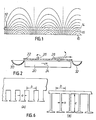
- a longitudinal flux single-sided linear induction motor primary 20 is disposed with its working face upwards below a conveyor belt 22 on to which a mixture of pieces of material, including non-ferrous metals, is to be deposited.
- the conveyor belt 22 moves in a direction perpendicular to the plane of the paper and the primary 20 produces a field of magnetomotive force which travels from left to right, as illustrated by the arrow 24.
- pieces of non-ferromagnetic electrically conductive material disposed on the conveyor belt, such as the pieces 26 and 28 are subject to a field of magnetomotice force which travels from left to right and are also subject to a force which attempts to rotate them in an anti-clockwise direction.
- pieces such as piece 26 Of dimensions in the direction of the travelling field substantially less than half the pole pitch of the motor, the rotating field predominates and such pieces are rolled towards the left, as viewed in Figure 2, off the side of the conveyor belt 22 and into a receptacle 30.
- pieces 28 of dimensions in the direction of the travelling field of the order of half the pole pitch of the motor or greater are subject to a force which displaces them from left to right, off the conveyor belt 22 and into another receptacle 32 on the other side thereof.
- the pieces 28 are, however, also subject to the rotating field components which tend to lift their leading edges, thereby assisting them in sliding over any particles not being moved by the motor which may lie in their path.
- a second linear induction motor primary 34 is arranged downstream of the motor-20 and parallel thereto, the conveyor belt 22 moving from left to right as viewed in Figure 3.
- the linear motor 34 has a shorter pole pitch than that of the motor 20.
- the motor 34 may be wound with one slot per pole per phase, the motor 20 is wound with two slots per pole per phase.
- the pole pitch of the motor 20 is twice that of the motor 34 and pieces of a size which would be left on the conveyor belt 22 by the motor 20 are displaced off the conveyor belt by the motor 34 in the direction of the travelling field.
- the axes of the motors 20 and 34 are not perpendicular to the direction of the movement of the conveyor belt 22 but are disposed at an angle such that the travelling magnetic field has a component opposing the direction of movement of the belt 22.
- the effect of this is to slow down the movement of electrically conductive pieces on the belt so that they are exposed to the influence of each motor for a longer period of time thereby increasing the probability that they will be displaced off the belt before the belt moves them out of range of the motor.
- Figure 4 illustrates the variation of the power P required to cause movement on the conveyor belt 22 of pieces of a particular non-ferromagnetic metal with the smallest dimension d of such pieces. It will be seen that the power P required increases as the dimension d decreases.
- the dimension d is the dimension of the material in close proximity to the conveyor belt 22. This is because the flux density falls off exponentially with distance above the surface. Consequently, in order to optimise the use of the available power, the pieces of material are preferably flattened and laid on the belt with their major dimensions perpendicular to the direction of movement of the belt.
- the material is preferably fed on to the belt from a hopper 40 with a pair of rolls 42 and 44 disposedbetween the outlet of the hopper 40 and the belt with their axes parallel to the axis of the driving roller 46 of the belt.
- Material from the hopper 40 is therefore flattened by the rolls 42 and 44 and deposited on the belt with the major dimension of the various pieces tending to be'oriented parallel to the axes of the rolls.
- the density of material which determines the frictional force which has to be overcome
- the electrical conductivity which determines the magnitude of the induced secondary current for a given flux.
- One way of increasing the effectiveness of the linear motors is to increase the frequency of the alternating current used to power the motors.
- the motors used to remove the aluminium may be powered at 50 Hz while the motors used to remove the copper may be powered at a higher frequency, up to about 500 Hz,
- the skin effect at the higher frequency has the result of reducing the apparent conductivity of the electrically conductive materials as frequency increases. Since for any particular frequency, skin depth increases as conductivity decreases, this has the effect of compressing the spread of apparent conductivity between different metals.
- the cores of the primaries of all linear induction motors for use in accordance with the invention should have a tooth width which is less than 30% of the tooth pitch.
- Figure 6A shows the configuration of the stator of a normal type of induction motor.
- Figure 6B shows by way of contrast the stator of a linear induction motor suitable for use in the metal sorting system of the present invention.
- the material conveyed by the conveyed 54 is deposited on to a first sieve 60 which removes the dust and very small particles from the mixture.
- the dust is collected by a first hopper 62.
- an air extractor system can be used at this stage.
- the larger remaining particles are transported by a second conveyor 70 past an overband electromagnet 72 which removes the ferromagnetic material from the mixture.
- the ferromagnetic material is attracted by the electromagnet 72 and on to a continuous belt 74 equipped with slats which is wiped across the face of the electromagnet and deposited into a hopper 76.
- the material left on the conveyor belt 70 is deposited on to a transfer sieve 78 which removes material below a predetermined dimension from the flow of material.
- the material falling through the sieve 78 is collected by a hopper 80 and the remaining material is deposited on to a further conveyor 82 driven at a predetermined speed by a drive roller 84.
- the conveyor 82 deposits the remaining material on to a further transfer sieve 86 which is of large dimension and therefore allows material of larger dimensions to fall into a hopper 88.
- the transfer sieve 78 is a one inch mesh the hopper 80 will contain only material under one inch in any one dimension. If the sieve 86 is a three inch mesh then the hopper 88 will contain material between one and three inches in dimension.
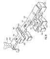
- FIG 8 there is shown a second metal sorting system according to the present invention.
- Material to be sorted is fed as for the system of Figure 7 into a fragmentiser 100 where it is smashed into relatively small pieces. These are transported by a conveyor l02 onto a dust sieve 104, the dust being collected in a hopper 106.
- a dust sieve 104 As above alternatively an air extraction system to remove the dust and light material may be used.
- the rest of the material is conveyed on a conveyor belt 108 past an overband electromagnet 110 which removes the ferromagnetic material.
- Material left on conveyor belt 108 is carried on to transfer a sieve 112 which is of relatively small mesh. Material of all types metal rubber and plastics falls on to a secondary conveyor belt 114, which moves at a constant predetermined speed in the direction shown.
- a linear induction motor 116 is mounted beneath the belt and when actuated causes the non -ferromagnetic metal on the conveyor to be deflected sideways off the conveyor to be collected in a hopper 118. Material such as plastics and rubber remaining on the conveyor is collected in a further hopper 120.
- Material too large for the sieve 112 is fed to a conveyor belt 122 underneath which are mounted two linear induction motors,124 and 126, motor 126 being downstream from motor 124.
- Non -ferromagnetic, material on the belt is deflected by the first motor 124 into a hopper 128 and by the second motor 126 into a hopper 130. Material left on the conveyor is collected by a hopper 132.
- the system of Figure 8 operates by separating at the sieve 112 the smaller pieces of non-ferromagnetic material and small pieces of plastics and rubber.
- the non-ferromagnetic material is separated from the rest by the linear motor 116.
- the larger pieces of material fed on to the conveyor 122 are fed to the linear motor 124 which is operated at a lower power than the motor 116. This motor therefore for example separates all the aluminium from the mixture.
- the remainder of the material is fed to the second linear induction motor 126 which is operated at a higher power and which thereby deflects the heavier metals such as brass, copper from the conveyor.
- FIG. 9 A further system utilising the principles of the present invention is shown in Figure 9. Again the material such as a motor car or part thereof is fed into a fragmentiser 150 the output material from which is fed via a conveyor 152 to a dust sieve 154 of fine mesh. The dust is collected in a hopper or bin 156. Material not passing through the sieve is passed to a conveyor belt 158 and ferromagnetic material is removed by an overband electromagnet 160.
- the remaining material comprising non-ferromagnetic metal rubber, plastics etc is fed via a small mesh sieve 162 to a conveyor 164. Material falling through the sieve 162 is collected in a hopper 166.
- the sieve 162 can merely be a further dust sieve to remove dust created by the removal of the ferromagnetic ' material or very small particles. Alternatively as in the arrangement of Figure 8 it can be of a mesh size to remove the relatively smaller pieces of material.
- Material on the conveyor belt 164 is fed past at least one linear motor 168 and the non-ferromagnetic metal deflected by this motor is collected in a hopper 170.
- a second linear induction motor could be situated downstream from the motor 168 to sort out other sizes or types of non-ferromagnetic metal.
- the conveyor belt 164 is inclined so that material passing the motor 168 and deflected by it may be assisted by rolling or sliding down the conveyor belt when lifted by the motor thus spending a greater period of time in the field of the motor. This can allow a lower power motor to be used relative to the size of non-ferromagnetic metal to be deflected.
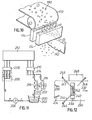
- the movement of the conductive material can be to the right as illustrated in Figure 10.
- the conductive material 180 falling between the poles of the double sided motor 174 is deflected to the right past a baffle 182 and is directed by the baffle to a hopper (not shown).
- each linear induction motor is important and the deflecting power of any motor depends on a number of factors including principally the design of the stator, the frequency of operation and the motor current.
- the motors in general however require large operating currents and hence the need to remove considerably more heat than is normally generated with conventional linear motors. For this reason it is preferred to water cool the motor, for example by using hollow copper tubes for the windings and forcing water through the tubes to provide the necessary cooling.
- a suitable cooling system is shown in Figure 11 in which water 200 is stored in a tank 202.
- a motor driven pump 204 circulates the water round the system in the direction shown back to the tank 200.
- the flow is split at 206 into three paths to supply each phase of the three phase linear induction motor.
- Each path has a respective air purge gate and has electrical isolation means 208, 210 on each side of the motor 212.
- the flow is recombined at 214 and is fed via radiators 216, 218 cooled by electric fans 220, 222 back to the tank 202. Numerous isolation valves are provided as shown.
- the linear induction motor may not always be of the same width as the conveyor especially if the sorting system is added to an existing installation.
- Figure 12 shows a solution to this problem.
- a conveyor 230 is moved in a direction indicated by arrow 232 by known conveyor drive means (not shown). Material is introduced onto the centre portion of the conveyor by baffles 234, 236.
- the linear induction motor 238 has a full travelling field zone 240 as shown shaded. The travelling field is in the direction shown by arrow 242.
- Deflectors 244 and 247, pivoted on pivots 245, 249 are adjusted and then fixed to push any material towards the centre of the conveyor belt 230.
- the non-ferro- magnetic material deflected by the motor 238 is either ejected directly into a hopper 246 or in the case of heavier or less conductive pieces onto a collector deflector 248 which guides the material into the hopper 246.
- Material fed onto any of the above described conveyer belt and linear motor systems is preferably .fed by a vibratory arrangement which effectively spreads the material on the conveyor and stabilises the load on the conveyor.
- the conveyor can be run at a relatively high speed with respect to any immediately upstream conveyors to spread out the material.
Landscapes
- Sorting Of Articles (AREA)
- Non-Mechanical Conveyors (AREA)
- Manufacture And Refinement Of Metals (AREA)
Applications Claiming Priority (2)
| Application Number | Priority Date | Filing Date | Title |
|---|---|---|---|
| GB7903621 | 1979-02-01 | ||
| GB7903621 | 1979-02-01 |
Publications (2)
| Publication Number | Publication Date |
|---|---|
| EP0014564A1 true EP0014564A1 (de) | 1980-08-20 |
| EP0014564B1 EP0014564B1 (de) | 1984-10-03 |
Family
ID=10502894
Family Applications (1)
| Application Number | Title | Priority Date | Filing Date |
|---|---|---|---|
| EP80300280A Expired EP0014564B1 (de) | 1979-02-01 | 1980-01-31 | Metallsortiersystem zum Abscheiden nicht ferromagnetischer Metalle aus zerkleinertem Material |
Country Status (7)
| Country | Link |
|---|---|
| US (1) | US4459206A (de) |
| EP (1) | EP0014564B1 (de) |
| JP (1) | JPS55127178A (de) |
| DE (2) | DE3069328D1 (de) |
| FR (1) | FR2447754A3 (de) |
| HK (1) | HK14484A (de) |
| SG (1) | SG65183G (de) |
Cited By (5)
| Publication number | Priority date | Publication date | Assignee | Title |
|---|---|---|---|---|
| EP0038767A3 (de) * | 1980-04-22 | 1983-09-28 | CENTRE STEPHANOIS DE RECHERCHES MECANIQUES HYDROMECANIQUE ET FROTTEMENT Société dite: | Verfahren und Vorrichtung zur Trennung von Materialteilchen durch Induktion |
| EP0095356A1 (de) * | 1982-05-26 | 1983-11-30 | Cotswold Research Limited | Linearmotorsysteme |
| EP0363166A1 (de) * | 1988-10-06 | 1990-04-11 | Peter Thomas Reid | Verfahren und Apparat zum Trennen von nichtmagnetischen elektrisch leitenden Materialien |
| US4948467A (en) * | 1989-05-17 | 1990-08-14 | The Black Clawson Company | Extended nip press with induced repulsion |
| EP0452025A1 (de) * | 1990-04-10 | 1991-10-16 | Peter Thomas Reid | Magnetische Methoden zur Trennung elektrisch leitender Materialien |
Families Citing this family (16)
| Publication number | Priority date | Publication date | Assignee | Title |
|---|---|---|---|---|
| US4541530A (en) * | 1982-07-12 | 1985-09-17 | Magnetic Separation Systems, Inc. | Recovery of metallic concentrate from solid waste |
| US4834870A (en) * | 1987-09-04 | 1989-05-30 | Huron Valley Steel Corporation | Method and apparatus for sorting non-ferrous metal pieces |
| JPH0212781U (de) * | 1988-07-11 | 1990-01-26 | ||
| US5080234A (en) * | 1990-08-15 | 1992-01-14 | Walker Magnetics Group, Inc. | Eddy current separator |
| US5133505A (en) * | 1990-10-31 | 1992-07-28 | Reynolds Metals Company | Separation of aluminum alloys |
| US5236136A (en) * | 1991-12-20 | 1993-08-17 | Michael W. McCarty | System and method for recycling used oil filters |
| US5341937A (en) * | 1992-12-16 | 1994-08-30 | Machinefabriek Bollegraaf Appingedam B.V. | Apparatus for separating recyclable waste |
| US5411147A (en) * | 1993-01-28 | 1995-05-02 | Bond; David S. | Dynamic landfill recycling system |
| US5522513A (en) * | 1994-03-30 | 1996-06-04 | Howell; Billy R. | Separator disc |
| RU2148437C1 (ru) * | 1999-07-01 | 2000-05-10 | Научно-производственное предприятие "Галактика" | Магнитный активатор суспензий |
| DE10003562A1 (de) * | 2000-01-27 | 2001-08-16 | Commodas Gmbh | Vorrichtung und Verfahren zum Aussortieren von metallischen Fraktionen aus einem Schüttgutstrom |
| DE10061698B4 (de) * | 2000-12-12 | 2005-01-27 | Jeanette Bauer | Verfahren und Einrichtung zum Trennen elektrisch leitfähiger, nicht-ferromagnetischer Partikel |
| US20080029445A1 (en) * | 2006-08-03 | 2008-02-07 | Louis Padnos Iron And Metal Company | Sorting system |
| JP4768575B2 (ja) * | 2006-10-31 | 2011-09-07 | 日立オートモティブシステムズ株式会社 | ソレノイドバルブ |
| DE102019000962B4 (de) * | 2019-02-09 | 2024-11-07 | Igor Danylyev | Verfahren auf Basis von Doppelstatorinduktoranordnungen mit Induktoren zur Generierung hochfrequenter, polyharmonischer elektromagnetischer Wanderwellen zur Anwendung in verschiedenen technologischen Prozessen der elektrodynamischen Separation nichtferromagnetischer, leitfähiger Materialien |
| CN114505168B (zh) * | 2022-02-28 | 2024-09-20 | 格林美(武汉)城市矿山产业集团有限公司 | 一种旋流器式涡电流分选机 |
Citations (6)
| Publication number | Priority date | Publication date | Assignee | Title |
|---|---|---|---|---|
| US1564732A (en) * | 1922-07-21 | 1925-12-08 | Weatherby Ore Separator Compan | Method and apparatus for separating ore particles |
| US3045821A (en) * | 1953-01-05 | 1962-07-24 | Cavanagh Daniel Alfred | Magnetic concentration method |
| FR2263822A1 (de) * | 1974-03-11 | 1975-10-10 | Occidental Petroleum Corp | |
| FR2314764A1 (fr) * | 1975-06-16 | 1977-01-14 | Occidental Petroleum Corp | Appareil de separation de materiaux utilisant un moteur lineaire |
| FR2320782A1 (fr) * | 1975-08-11 | 1977-03-11 | Occidental Petroleum Corp | Procede et appareillage de recuperation de metaux non-ferreux dans des detritus solides |
| US4137156A (en) * | 1975-03-21 | 1979-01-30 | Occidental Petroleum Corporation | Separation of non-magnetic conductive metals |
Family Cites Families (9)
| Publication number | Priority date | Publication date | Assignee | Title |
|---|---|---|---|---|
| US3111484A (en) * | 1953-01-05 | 1963-11-19 | Cavanagh Daniel Alfred | Magnetic concentration apparatus |
| US2971703A (en) * | 1958-06-04 | 1961-02-14 | Frank E Rath | Process for cleaning and recovering scrap metal from slag and the like |
| NL130732C (de) * | 1965-06-22 | |||
| US3905556A (en) * | 1974-05-20 | 1975-09-16 | Air Prod & Chem | Method and apparatus for recovery of metals from scrap |
| US3950661A (en) * | 1974-06-19 | 1976-04-13 | Occidental Petroleum Corporation | Linear induction motor with artificial transmission line |
| NL181177C (nl) * | 1975-03-29 | 1987-07-01 | Stamicarbon | Werkwijze voor het terugwinnen van bruikbare materialen uit afvalmateriaal dat metalen en niet-metalen bevat. |
| SU659188A1 (ru) * | 1977-11-02 | 1979-04-30 | Днепропетровский Ордена Трудового Красного Знамени Горный Институт Им. Артема | Электродинамический сепаратор |
| US4362276A (en) * | 1977-12-08 | 1982-12-07 | Occidental Research Corporation | Process and apparatus for recovering metal and plastic from insulated wire |
| JPS54122466A (en) * | 1978-03-16 | 1979-09-22 | Shinko Electric Co Ltd | Linear motor type nonmagnetic metal selector |
-
1980
- 1980-01-31 DE DE8080300280T patent/DE3069328D1/de not_active Expired
- 1980-01-31 FR FR8002123A patent/FR2447754A3/fr active Granted
- 1980-01-31 EP EP80300280A patent/EP0014564B1/de not_active Expired
- 1980-02-01 JP JP1140180A patent/JPS55127178A/ja active Granted
- 1980-02-01 DE DE19808002678U patent/DE8002678U1/de not_active Expired
-
1982
- 1982-04-15 US US06/368,742 patent/US4459206A/en not_active Expired - Fee Related
-
1983
- 1983-11-02 SG SG651/83A patent/SG65183G/en unknown
-
1984
- 1984-02-16 HK HK144/84A patent/HK14484A/xx unknown
Patent Citations (6)
| Publication number | Priority date | Publication date | Assignee | Title |
|---|---|---|---|---|
| US1564732A (en) * | 1922-07-21 | 1925-12-08 | Weatherby Ore Separator Compan | Method and apparatus for separating ore particles |
| US3045821A (en) * | 1953-01-05 | 1962-07-24 | Cavanagh Daniel Alfred | Magnetic concentration method |
| FR2263822A1 (de) * | 1974-03-11 | 1975-10-10 | Occidental Petroleum Corp | |
| US4137156A (en) * | 1975-03-21 | 1979-01-30 | Occidental Petroleum Corporation | Separation of non-magnetic conductive metals |
| FR2314764A1 (fr) * | 1975-06-16 | 1977-01-14 | Occidental Petroleum Corp | Appareil de separation de materiaux utilisant un moteur lineaire |
| FR2320782A1 (fr) * | 1975-08-11 | 1977-03-11 | Occidental Petroleum Corp | Procede et appareillage de recuperation de metaux non-ferreux dans des detritus solides |
Cited By (7)
| Publication number | Priority date | Publication date | Assignee | Title |
|---|---|---|---|---|
| EP0038767A3 (de) * | 1980-04-22 | 1983-09-28 | CENTRE STEPHANOIS DE RECHERCHES MECANIQUES HYDROMECANIQUE ET FROTTEMENT Société dite: | Verfahren und Vorrichtung zur Trennung von Materialteilchen durch Induktion |
| EP0095356A1 (de) * | 1982-05-26 | 1983-11-30 | Cotswold Research Limited | Linearmotorsysteme |
| WO1983004194A1 (en) * | 1982-05-26 | 1983-12-08 | Eric Roberts Laithwaite | Improvements in or relating to linear motor systems |
| EP0363166A1 (de) * | 1988-10-06 | 1990-04-11 | Peter Thomas Reid | Verfahren und Apparat zum Trennen von nichtmagnetischen elektrisch leitenden Materialien |
| US4948467A (en) * | 1989-05-17 | 1990-08-14 | The Black Clawson Company | Extended nip press with induced repulsion |
| WO1990014466A1 (en) * | 1989-05-17 | 1990-11-29 | The Black Clawson Company | Extended nip press with induced repulsion |
| EP0452025A1 (de) * | 1990-04-10 | 1991-10-16 | Peter Thomas Reid | Magnetische Methoden zur Trennung elektrisch leitender Materialien |
Also Published As
| Publication number | Publication date |
|---|---|
| DE3069328D1 (en) | 1984-11-08 |
| SG65183G (en) | 1985-03-29 |
| JPS55127178A (en) | 1980-10-01 |
| US4459206A (en) | 1984-07-10 |
| DE8002678U1 (de) | 1980-07-17 |
| EP0014564B1 (de) | 1984-10-03 |
| HK14484A (en) | 1984-02-24 |
| JPS633673B2 (de) | 1988-01-25 |
| FR2447754A3 (fr) | 1980-08-29 |
| FR2447754B3 (de) | 1981-01-02 |
Similar Documents
| Publication | Publication Date | Title |
|---|---|---|
| US4459206A (en) | Separation of non-ferromagnetic metals from fragmented material | |
| US4137156A (en) | Separation of non-magnetic conductive metals | |
| GB2178344A (en) | Gravity - magnetic ore separators | |
| US4668381A (en) | Method of and apparatus for separating electrically conductive non-ferrous metals | |
| CN109433414A (zh) | 涡电流分选机装置 | |
| US2217300A (en) | swart | |
| US4083774A (en) | Magnetic segregation of mixed non-ferrous solid materials in refuse | |
| EP0881952B1 (de) | Verfahren und vorrichtung zur steigerung der trennschärfe von wirbelstromscheidern | |
| GB2040735A (en) | Separation of non-ferromagnetic metals from fragmented material | |
| CA1041949A (en) | Linear electric motor field separating aluminum particles transversely | |
| DE2509638A1 (de) | Abtrennungsverfahren und vorrichtung zur durchfuehrung | |
| US4029573A (en) | Waste segregating apparatus | |
| MX2014012145A (es) | Separador que emplea corrientes de foucault. | |
| JP3276801B2 (ja) | 金属破砕分別方法及びシステム | |
| US4070278A (en) | Magnetic segregation of mixed non-ferrous solid materials in refuse | |
| EP0095356B1 (de) | Linearmotorsysteme | |
| EP0579966A1 (de) | Verfahren und Vorrichtung zum Abtrennen nichtmagnetisierbarer Metalle aus einem Gemisch | |
| Kercher et al. | Scrap processing by eddy current separation techniques | |
| CA1063552A (en) | Translating magnetic fields in non-magnetic conductive metals separation system | |
| CA1051384A (en) | Separation of non-magnetic conductive metals | |
| US11958058B2 (en) | System for sorting metallic objects | |
| RU1787551C (ru) | Электромагнитный сепаратор | |
| DE2902219C2 (de) | Magnetscheider | |
| SU934600A1 (ru) | Способ электродинамической сепарации | |
| CN213996262U (zh) | 一种组合涡流分选机 |
Legal Events
| Date | Code | Title | Description |
|---|---|---|---|
| PUAI | Public reference made under article 153(3) epc to a published international application that has entered the european phase |
Free format text: ORIGINAL CODE: 0009012 |
|
| AK | Designated contracting states |
Designated state(s): BE DE FR IT SE |
|
| 17P | Request for examination filed |
Effective date: 19810216 |
|
| ITF | It: translation for a ep patent filed | ||
| GRAA | (expected) grant |
Free format text: ORIGINAL CODE: 0009210 |
|
| AK | Designated contracting states |
Designated state(s): BE DE FR IT SE |
|
| REF | Corresponds to: |
Ref document number: 3069328 Country of ref document: DE Date of ref document: 19841108 |
|
| ET | Fr: translation filed | ||
| PLBE | No opposition filed within time limit |
Free format text: ORIGINAL CODE: 0009261 |
|
| STAA | Information on the status of an ep patent application or granted ep patent |
Free format text: STATUS: NO OPPOSITION FILED WITHIN TIME LIMIT |
|
| 26N | No opposition filed | ||
| ITTA | It: last paid annual fee | ||
| PGFP | Annual fee paid to national office [announced via postgrant information from national office to epo] |
Ref country code: FR Payment date: 19900131 Year of fee payment: 11 |
|
| PGFP | Annual fee paid to national office [announced via postgrant information from national office to epo] |
Ref country code: BE Payment date: 19900221 Year of fee payment: 11 |
|
| PGFP | Annual fee paid to national office [announced via postgrant information from national office to epo] |
Ref country code: SE Payment date: 19900223 Year of fee payment: 11 |
|
| PGFP | Annual fee paid to national office [announced via postgrant information from national office to epo] |
Ref country code: DE Payment date: 19900228 Year of fee payment: 11 |
|
| PG25 | Lapsed in a contracting state [announced via postgrant information from national office to epo] |
Ref country code: BE Effective date: 19910131 |
|
| PG25 | Lapsed in a contracting state [announced via postgrant information from national office to epo] |
Ref country code: SE Effective date: 19910201 |
|
| PG25 | Lapsed in a contracting state [announced via postgrant information from national office to epo] |
Ref country code: FR Effective date: 19910930 |
|
| PG25 | Lapsed in a contracting state [announced via postgrant information from national office to epo] |
Ref country code: DE Effective date: 19911001 |
|
| REG | Reference to a national code |
Ref country code: FR Ref legal event code: ST |
|
| EUG | Se: european patent has lapsed |
Ref document number: 80300280.7 Effective date: 19911002 |