EP0014618A1 - Dispositif joint tournant pour liaison par conducteurs optiques et son utilisation entre deux corps tournants - Google Patents
Dispositif joint tournant pour liaison par conducteurs optiques et son utilisation entre deux corps tournants Download PDFInfo
- Publication number
- EP0014618A1 EP0014618A1 EP80400100A EP80400100A EP0014618A1 EP 0014618 A1 EP0014618 A1 EP 0014618A1 EP 80400100 A EP80400100 A EP 80400100A EP 80400100 A EP80400100 A EP 80400100A EP 0014618 A1 EP0014618 A1 EP 0014618A1
- Authority
- EP
- European Patent Office
- Prior art keywords
- end piece
- conductors
- bodies
- rotating
- rotation
- Prior art date
- Legal status (The legal status is an assumption and is not a legal conclusion. Google has not performed a legal analysis and makes no representation as to the accuracy of the status listed.)
- Granted
Links
Images

Classifications
-
- G—PHYSICS
- G02—OPTICS
- G02B—OPTICAL ELEMENTS, SYSTEMS OR APPARATUS
- G02B6/00—Light guides; Structural details of arrangements comprising light guides and other optical elements, e.g. couplings
- G02B6/24—Coupling light guides
- G02B6/36—Mechanical coupling means
- G02B6/3604—Rotary joints allowing relative rotational movement between opposing fibre or fibre bundle ends
Definitions
- the present invention relates to a rotating joint device allowing a connection by optical conductors between two mechanical bodies rotating with respect to one another about a common axis of rotation.
- optical conductor is to be considered in the general sense, including both the monofiber and the multifiber version, that is to say fiber optic bundles, to which the invention can also be applied.
- Optical fibers are generally conductors of small dimensions, for example 100 ⁇ m in external diameter and 50 ⁇ m for the diameter of the core.
- the optical coupling between the opposite end faces of the conductors to be connected can only remain satisfactorily ensured if the mechanical clearances, introduced during the relative rotation of the external bodies, remain compatible with fine tolerances predetermined in relation to the dimensions of the fibers. This cannot be easily satisfied, especially when the mechanical bodies are large, or would require a prohibitive cost due to the high machining precision.
- the presence of mechanical play can cause, during each rotation, a variation in the relative positioning of the bodies in the axial direction; in addition, the mechanical axes of the two bodies may not remain coincident in a common direction of rotation and present a relative inclination (lack of parallelism) and / or a transverse offset (defect of centou).
- These variations reported on the faces of the conductors facing each other, cause a corresponding degradation of the optical coupling.
- the rotary joint device according to the present invention overcomes these drawbacks by preserving precise positioning of the facing end faces and by ensuring excellent optical coupling and high reliability of the transmission.
- connectors for optical conductors in which the two conductors can rotate axially with respect to each other and which comprise, a male part and a female part rotating one inside the other via mechanical positioning devices, for example, ball bearings.
- mechanical positioning devices for example, ball bearings.
- a rotary joint device for connection by optical conductors between two annex bodies rotating one relative to the other about an axis of rotation, comprising a male end piece ending in a part cylindrical and a female end piece terminated by a bored part, the end pieces being mechanically coupled respectively to said bodies as well as for turning one inside the other around the axis of rotation and being arranged to receive axially one end of the conductor and so that the corresponding end faces of the conductors are arranged parallel opposite and centered on the axis, and-being characterized in that the diameters of the cylindrical part and of the bored part are predetermined substantially of the same value to make an adjustment uncertain, allowing rotation as well as relative axial displacement, the end pieces being arranged to produce a mechanical stop device delimiting said axial movement, one end being rigidly coupled to one of the bodies and the other end being coupled to the other body according to a semi-rigid assembly to isolate the joint from variations in positioning between the two rotating bodies generated by mechanical play.
- the rotary joint device shown in FIG. 1 comprises a male part 1 and a female part 2 which can rotate relative to each other about a common axis a constituting the axis of rotation of the external bodies A and B to which these parts are respectively coupled.
- Each part constitutes an end piece for the optical conductor associated with it.
- the drivers F1 and F2 optics can consist of one or more fibers depending on whether the connection is monofiber or with fiber bundles.
- Each of the end pieces 1 and 2 is axially hollowed out to receive the corresponding optical conductor F1 and F2 and centering means 3 and 5 are provided at the end of the conductors to center with precision the end faces of the conductors on the axis ⁇ and according to a plane orthogonal to the axis.
- the male end piece 1 has a cylindrical end portion 5 or shaft, the female end piece 2 ending in a reamed part 6 of diameter D1 (Fig.2) corresponding to produce a rotary assembly with determined tolerances.
- the machining of the cylindrical surfaces in contact is carried out with precision to obtain a so-called uncertain adjustment, that is to say without play and without tightening.
- the assembly is made sliding or rotating for careful fabrication, for example, with a normal bore H7, a rotating assembly H7-f7, or sliding H7-g6 or just sliding H7-h6 can be produced. The choice depends essentially on the speed of rotation and the periods of continuous operation envisaged.
- the end faces of the conductors F1 and F2 are coplanar with the end surfaces 51 of the shaft 5 and 61 of the bored part 6 forming a sleeve.
- the shaft 5 is terminated at its other end by a portion of larger diameter 7 forming a base with a surface 71 on which the surface 62 which abuts the sleeve 6 can abut.
- the axial dimensions H3 and H4 of the elements 5 and 6 are determined such that the distance e between the transverse surfaces 51 and 61, that is to say between the parallel faces and facing the conductors Fl and F2, has a predetermined minimum value em, equal to H3 -H4, for the position in abutment of the surface 62.
- the rotary joint device is arranged to present a second axial abutment position to which corresponds a maximum ⁇ M interface between the optical conductors.
- the corresponding stop device is produced by a part 8 mechanically secured by screwing the base 7 which is laterally threaded for this purpose.
- the part 8 has a corresponding threaded lateral part for assembly, a hollowed-out part of diameter D2 greater than that D3 of the sleeve 6 and an end part of diameter D4 less than D3 to provide a housing in which the sleeve 6 can move.
- the second stop position is obtained when the transverse surfaces shown 63 and 81 of the elements 6 and 8 come into contact.
- the sleeve 6 is followed by a cylindrical part or barrel 9 whose diameter D5 is less than that D4 of the terminal part of the part 8.
- the mechanical coupling of the ends 1 and 2 to the annex bodies A and B can be carried out as shown by means of flanges 10 and 11, one of the couplings being rigid and the other semi-rigid, or elastic.
- the rotary joint preserves the centering of the conductors F1 and F2 and their optical coupling, in the presence of axial displacements and defects in parallelism and centering presented during the rotation between the parts A and B.
- One of the flanges, the flange 10 in the illustrated example is rigidly fixed by screws 12 to the body A and is constituted by a machined part of the part 8.
- the fasteners 12 are distributed regularly over a circumference; the distribution can include, for example, three fixings at 120 ° from one another.
- the flange 11 of the female end piece 2 is formed by a piece screwed onto the threaded end lateral part of the barrel 9, so as to allow the preassembly of the sleeve 6 on the shaft 5, then the screwing of the piece 8 on the 'base 7.
- the semi-rigid coupling to the body B is achieved by means of screws 13 and rings 14 passing through slots 15 of dimension L greater than the diameter of the rings (detail fig.3).
- the support rings 14 are made of hard, slippery material, for example of hard nylon.
- the height H of the rings 14 is greater than the thickness E of the flange 11 to allow axial movements between the bodies A and B.
- the slots or slots 15 are also distributed over a circumference.
- the rotary joint device is supported by the external body to which it is rigidly fixed, the body A in the example shown, it being understood that the couplings can be reversed.
- the axis A can have any position, vertical as figured, or horizontal, or other.
- the figures 4-a and 4-b represent an alternative embodiment of the semi-rigid coupling.
- the ring is replaced there by an oblong part 20, of elliptical section, which can pivot around the screw 13.
- a spiral spring 21 fixed on the one hand to the screw 13 and on the other hand to the part 20 forces the latter coming to rest on the sides of the slot 15. This makes it possible to avoid jolts, in particular in the event of a change in the direction of rotation, acceleration or deceleration.
- FIG. 5 relates to a preferred embodiment of the centering means 3 and 4 of the ends of the conductors F1, F2.
- the mechanical part, the shaft 5 for example, has an end bore 25 filled with a material 26 capable of exhibiting the creep phenomenon, the latter being defined as a capacity for deformation similar to that of a viscous fluid subjected to high pressure.
- This material can be a metal (lead, tin, antimony), or a plastic such as a polyamide or a polycarbonate or a polyfluorethene, of hardness lower than that of the glass constituting the conductor.
- a corresponding centering technique is described in French patent application No. 76.13003 published under No. 2,349,843.
- the conductor F1 is stripped in its terminal part of its outer plastic envelope 27 to reveal, in the case of a single fiber, the sheath 28 surrounding the core 29. After creep and hardening, the end of the fiber is perfectly centered and is machined to be made coplanar with the surface 51 and to present an optical polish. Curing can be obtained by cooling the previously heated material (in the case of metals) or by final thermal action (in the case of plastics).
- the attached device '- ' urnant is arranged to include lubrication means facilitating the rotation of the parts and sparing wear due to friction, the liquid used being chosen according to its refractive index in order to do not disturb the optical link in the interface part between the conductors.
- Liquid 30 is a lubricant and an index adapter, introduced beforehand and which can be: glycerin, eucalyptol, cedar oil, various immersion oils, naplital monobromide, etc.
- the mechanical arrangements include seals of etan cheity 31, 32, a spring 33 and a washer 34.
- the end part of the part 8 forming a support stop for the spring is constituted by a threaded insert-35.
- the compression of the spring 33 exerts a pressure on the surface 63 and the sleeve 6 is sheathed in abutment, the surface 62 coming into contact with the surface 71 of the base 7.
- the circulation of the fluid 30 can be exerted by capillarity or can be facilitated by means of grooves forming conduits and machined to this effect on the surfaces in contact with the elements 5 and 6.
- the diagram in figure 7 illustrates an example of application.
- the body B is fixed and the body A rotated about the axis ⁇ .
- the drive means are symbolized by bearings 40.
- An optical transmitter is installed in the structure A comprising means generating data 41, an amplifier 42, a photoemissive diode 43 and a connector 44 to the fiber F1.
- the fiber F2 is connected by a connector 45 to a receiver grouping for example a photodetector diode 46, an amplifier 47, a threshold comparator 48 and means for processing and exploiting the data 49.
- the rotary joint 1-2 allows , in accordance with the invention, to mechanically separate the interface positioning of the conductors from the effects resulting from mechanical play in the external structures, A, B and 40 during rotation, these effects being able to result in relative axial, transverse displacements to the axis, or angular as it was detailed previously.
- the dimensions of the flange 11, in particular its thickness E (fig.l) and the width L of the lights (fig.3) are determined in relation to the dimensions of the fixing and support elements 13, 14 and taking into account the amplitudes of the relative movements presented between the parts A and B during the rotation, in particular of the axial relative movement.
Landscapes
- Physics & Mathematics (AREA)
- General Physics & Mathematics (AREA)
- Optics & Photonics (AREA)
- Mechanical Coupling Of Light Guides (AREA)
Abstract
Description
- La présente invention concerne un dispositif joint tournant permettant une liaison par conducteurs optiques entre deux corps mécaniques tournant l'un par rapport à l'autre autour d'un axe commun de rotation.
- L'invention est plus particulièrement envisagée pour assurer la transmission de signaux optiques avec une grande fiabilité,dans le cas d'une liaison monofibre. Néanmoins, le terme de conducteur optique est à considérer dans le sens général, incluant aussi bien la version monofibre que celle multifibre, c'est-à-dire à faisceaux de fibres optiques, à laquelle l'invention peut également s'appliquer.
- Les fibres optiques sont généralement des conducteurs de faibles dimensions, par exemple 100 µm de diamètre extérieur et 50 µm pour le diamètre du coeur. D'autre part, le couplage optique entre les faces d'extrémité en regard des conducteurs à relier ne peut rester assuré de manière satisfaisante que si les jeux mécaniques, introduits au cours de la rotation relative des corps extérieurs, restent compatibles avec des tolérances fines prédéterminées en relation avec les dimensions des fibres. Ceci ne peut être satisfait aisément, surtout lorsque les corps mécaniques sont de grandes dimensions, ou bien nécessiterait un coût prohibitif par suite de la précision élevée d'usinage.
- La présence de jeux mécaniques peut provoquer, au cours de chaque rotation, une variation du positionnement relatif des corps selon la direction axiale ; en outre, les axes mécaniques des deux corps peuvent ne pas rester coincidants selon une direction commune de rotation et présenter une inclinaison relative (défaut de parallélisme) et/ou un décalage transversal (défaut de centrage). Ces variations, reportées au niveau des faces des conducteurs en regard, entraînent une dégradation correspondante du couplage optique.
- Le dispositif joint tournant selon la présente invention, permet de remédier à ces inconvénients en préservant un positionnement précis des faces d'extrémité en regard et en assurant, un excellent couplage optique et une fiabilité élevée de la transmission.
- Il est connu de réaliser des connecteurs pour conducteurs optiques dans lesquels les deux conducteurs peuvent tourner axialement l'un par rapport à l'autre et qui comportent, une partie mâle et une partie femelle tournant l'une dans l'autre par l'intermédiaire d'organes mécaniques de positionnement par exemple, des roulements à billes. Ces montages ne sont pas prévus pour constituer un joint tournant proprement dit et tenir compte de déplacements axiaux et de défauts de parallélisme ou de centrage pouvant se produire au cours de la rotation relative des deux corps extérieurs.
- Selon une caractéristique de l'invention, il est réalisé un dispositif joint tournant pour liaison par conducteurs optiques entre deux corps annexes tournant l'un par rapport à l'autre autour d'un axe de rotation, comportant un embout mâle terminé par une partie cylindrique et un embout femelle terminé par une partie alésée, les embouts étant couplés mécaniquement respectivement auxdits corps ainsi que pour tourner l'un dans l'autre autour de l'axe de rotation et étant aménagés pour recevoir axialement une extrémité de conducteur et en sorte que les faces d'extrémité correspondante des conducteurs se trouvent disposées parallèlement en regard et centrées sur l'axe, et-étant caractérisé en ce que les diamètres de la partie cylindrique et de la partie alésée sont prédéterminés sensiblement de même valeur pour réaliser un ajustement incertain, autorisant la rotation ainsi qu'un déplacement axial relatif, les embouts étant aménagés pour réaliser un dispositif de butée mécanique délimitant ledit déplacement axial, un embout étant couplé rigidement à l'un des corps et l'autre embout étant couplé à l'autre corps selon un assemblage semi-rigide pour isoler le joint des variations de positionnement entre les deux corps en rotation engendré par des jeux mécaniques.
- Les particularités et avantages d'un dispositif joint tournant conforme à la présente invention apparaîtront dans la description qui suit donnée à tit e d'exemple non limitatif à l'aide des figures annexées qui représentent :
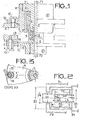
- - la figure 1, un exemple de réalisation avec demi-coupe axiale, d'un dispositif joint tournant selon l'invention ;
- - la figure 2, un schéma relatif aux cotes principales d'usinage ;
- - la figure 3, un schéma de détail d'un des couplages mécaniques aux corps extérieurs ;
- - les figures 4a et b, une variante de réalisation du couplage de la figure 3 ;
- - la figure 5, un schéma de détail d'une solution préférée pour le centrage des conducteurs optiques ;
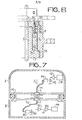
- - la figure 6, un schéma partiel d'une variante de réalisation du joint tournant de la figure 1 ; et
- - la figure 7, un schéma simplifié d'une application d'un dispositif joint tournant conforme à l'invention.
- Le dispositif joint tournant représenté sur la figure 1 comporte une partie mâle 1 et une partie femelle 2 pouvant tourner l'une par rapport à l'autre autour d'un axe commun a constituant l'axe de rotation des corps extérieurs A et B auxquels ces parties sont respectivement couplées. Chaque partie constitue un embout pour le conducteur optique qui lui est associé. Les conducteurs optiques Fl et F2 peuvent consister en une ou plusieurs fibres selon que la liaison est monofibre ou à faisceaux de fibres. Chacun des embouts 1 et 2 est évidé axialement pour recevoir le conducteur optique Fl et F2 correspondant et des moyens de centrage 3 et 5 sont prévus en extrémité des conducteurs pour centrer avec pécision les faces d'extrémité des conducteurs sur l'axe Δ et selon un plan orthogonal à l'axe.
- L'embout mâle 1 présente une partie cylzndrîque 5 d'extrémité ou arbre, l'embout femelle 2 se terminant par une partie alésée 6 de diamètre Dl (Fig.2) correspondant pour réaliser un assemblage tournant avec des tolérances déterminées. L'usinage des surfaces cylindriques en contact est réalisé avec précision pour obtenir un ajustement dit incertain, c'est-à-dire sans jeu et sans serrage. Selon la qualité requise l'assemblage est réalisé glissant ou tournant pour une fa- brïcation soignée par exemple, avec un alésage normal H7 on peut réaliser un assemblage tournant H7-f7, ou glissant H7-g6 ou glissant juste H7-h6. Le choix dépend essentiellement de la vitesse de rotation-et des durées de fonctionnement continu envisagées.
- Les faces d'extrémité des conducteurs Fl et F2 sont coplanaires avec les surfaces d'extrémité 51 de l'arbre 5 et 61 de la partie alésée 6 formant un manchon.
- L'arbre 5 est terminé par son autre extrémité par une partie de plus fort diamètre 7 formant une embase avec une surface 71 sur laquelle peut venir buter la surface 62 qui termine le manchon 6. Les cotes axiales H3 et H4 des éléments 5 et 6 (fig.2) sont déterminées telles que la distance e entre les surfaces transversales 51 et 61, c'est-à-dire entre les faces parallèles et en regard des conducteurs Fl et F2, présente une valeur minimale em prédéterminée, égale à H3-H4, pour la position en butée de la surface 62. Le dispositif joint tournant est aménagé pour présenter une deuxième position de butée axiale à laquelle correspond un interface εM maximal entre les conducteurs optiques. Le dispositif de butée correspondant est produit par une pièce 8 solidaire mécaniquement par vissage de l'embase 7 laquelle est filetée latéralement à cet effet. La pièce 8 présente une partie latérale filetée correspondante pour l'assemblage, une partie évidée de diamètre D2 supérieur à celui D3 du manchon 6 et une partie terminale de diamètre D4 inférieur à D3 pour ménager un logement dans lequel peut se déplacer le manchon 6. La deuxième position de butée est obtenue lorsque les surfaces transversales représentées 63 et 81 des éléments 6 et 8 viennent en contact. Le manchon 6 est suivi d'une partie cylindrique ou fût 9 dont le diamètre D5 est inférieur à celui D4 de la partie terminale de la pièce 8. En appelant H2 la longueur axiale du manchon 6 et Hl celle de la cavité, la différence Hl-H2 représentela plage totale Δε de déplacement axial relatif des embouts 1 et 2, l'interface maximal étant donné par εM = em + Δε.
- Le couplage mécanique des embouts 1 et 2 aux corps annexes A et B peut s'effectuer comme représenté au moyen de brides 10 et 11, l'un des couplages étant rigide et l'autre semi-rigide, ou élastique. Ainsi le joint tournant préserve le centrage des conducteurs Fl et F2 et leur couplage optique, en présence des déplacements axiaux et de défauts de parallèlisme et de centrage présentés aux cours de la rotation entre les pièces A et B. L'une des brides, la bride 10 dans l'exemple figuré, est fixée rigidement par des vis 12 au corps A et est constituée par une partie usinée de la pièce 8. Les fixations 12 sont réparties régulièrement sur une circonférence ; la répartition peut comporter par exemple trois fixations à 120° l'une de l'autre.
- La bride 11 de l'embout femelle 2 est formée par une pièce vissée sur la partie latérale terminale filetée du fût 9, de manière à autoriser les montages préaiables du manchon 6 sur l'arbre 5, puis le vissage de la pièce 8 sur l'embase 7. Le couplage semi-rigde au corps B est réalisé au moyen de vis 13 et de bagues 14 passant par des lumières 15 de dimension L supérieure au diamètre des bagues (détail fig.3). Les bagues d'appui 14 sont en matériau dur et glissant, en nylon dur par exemple. La hauteur H des bagues 14 est supérieure à l'épaisseur E de la bride 11 pour permettre des débattements axiaux entre les corps A et B. Les lumières ou fentes 15 sont également réparties sur une circonférence.
- Il y a lieu de remarquer que le dispositif joint tournant est supporté par le corps extérieur aquel il est fixé rigidement, le corps A sur l'exemple figuré, étant entendu que les couplages peuvent être inversés. Dans le même concept, l'axe A peut avoir une position quelconque, verticale comme figurée, ou horizontale, ou autre.
- Les couplages peuvent être réalisés de diverses manières, les figures 4-a et 4-b représentent une variante de réalisation du couplage semi-rigide. La bague s'y trouve remplacée par une pièce oblongue 20, de section elliptique, pouvant pivoter autour de la vis 13. Un ressort spiral 21 fixé d'une part à la vis 13 et d'autre part à la pièce 20 oblige cette dernière à venir s'appuyer sur les flancs de la fente 15. Ceci permet d'éviter les à-coups, notamment en cas de changement du sens de rotation, accélération ou décélération.
- La figure 5 a trait à une réalisation préférentielle des moyens de centrage 3 et 4 des extrémités des conducteurs Fl, F2. La pièce mécanique, l'arbre 5 par exemple, comporte un alésâge 25 d'extrémité rempli d'un matériau 26 apte à présenter le phénomène de fluage, ce dernier étant défini comme une aptitude à la déformation analogue à celle d'un fluide visqueux soumis à une forte pression. Ce matériau peut être un métal (plomb, étain, antimoine), ou un plastique tel un polyamide ou un polycarbonate ou un polyfluorethène, de dureté inférieure à celle du verre constituant le conducteur. Une technique de centrage correspondante est décrite dans la demande de brevet français n° 76.13003 Publiée sous le n° 2.349.843. Le conducteur Fl est dénudé dans sa partie terminale de son enveloppe plastique extérieure 27 pour laisser apparaître, dans le cas d'une fibre unique, la gaine 28 entourant le coeur 29. Après fluage et durcissement, l'extrémité de la fibre se trouve parfaitement centrée et est usinée pour être rendue coplanaire avec la surface 51 et présenter un poli optique. Le durcissement peut être obtenu par refroidissement du matériau préalablement chauffé (cas des métaux) ou par action thermique finale (cas des plastiques).
- Selon un mode préférentiel de réalisation, le dispositif joint '-'urnant est aménagé pour comporter des moyens de lubrification facilitant la rotation des pièces et ménageant l'usure due aux frottements, le liquide utilisé étant choisi en fonction de son indice de réfraction afin de ne pas perturber la liaison optique dans la partie interface entre les conducteurs.
- D'autre part, des moyens mécaniques sont prévus pour exercer une pression axiale en sorte que le manchon vienne en butée sur l'ambase 7 et que le jeu d'interface présente la valeur minimale Em. La figure 6 donne un exemple d'amménagement correspondant. Le liquide 30 est un lubrifiant et un adaptateur d'indice, introduit au préalable et pouvant être : de la glycérine, eucalyptol, huile de cèdre, huiles d'immersion diverses, monobromure de naplital, etc... Les aménagements mécaniques comportent des joints d'étanchéité 31, 32, un ressort 33 et une rondelle 34. La partie terminale de la pièce 8 formant butée d'appui pour le ressort est constituée par un élément fileté rapporté-35. La compression du ressort 33 exerce une pression sur la surface 63 et le manchon 6 est entfainé en butée, la surface 62 venant en contact avec la surface 71 de l'am- base 7. La circulation du fluide 30 peut s'exercer par- capillarité ou peut être facilitée au moyen de raihures formant condui'ts et usinées à cet éffet sur les surfaces en contact des éléments 5 et 6.
- Le schéma figure 7 illustre un exemple d'appli- cation. Le corps B est fixe et le corps A entraîné en rotation autour de l'axe Δ. Les moyens d'entraînement sont symbolisés par des roulements 40. Un émetteur optique est installé dans la structure A comportant des moyens générateurs de données 41, un amplificateur 42, une diode photoémissive 43 et un connecteur 44 à la fibre Fl. Dans la structure B, la fibre F2 est connectée par un connecteur 45 à un récepteur groupant par exemple une diode photodétectrice 46, un amplificateur 47, un comparateur à seuil 48 et des moyens de traitement et d'exploitation des données 49. Le joint tournant 1-2 permet, conformément à l'invention, de désolidariser mécaniquement le positionnement d'interface des conducteurs des effets résultant des jeux mécaniques dans les structures externes, A, B et 40 lors de la rotation, ces effets pouvant se traduire par des déplacements relatifs axiaux, transversaux à l'axe, ou angulaire comme il a été détaillé précédemment. Il est entendu que les dimensions de la bride 11, notamment son épaisseur E (fig.l) et la largeur L des lumières (fig.3) sont déterminées en relation avec les dimensions des éléments de fixation et d'appui 13, 14 et en tenant compte des amplitudes des mouvements relatifs présentés entre les pièces A et B au cours de la rotation, notamment du mouvement relatif axial.
Claims (10)
Applications Claiming Priority (2)
| Application Number | Priority Date | Filing Date | Title |
|---|---|---|---|
| FR7903136 | 1979-02-07 | ||
| FR7903136A FR2448728A1 (fr) | 1979-02-07 | 1979-02-07 | Dispositif joint tournant pour liaison par conducteurs optiques et systeme comportant un tel dispositif |
Publications (2)
| Publication Number | Publication Date |
|---|---|
| EP0014618A1 true EP0014618A1 (fr) | 1980-08-20 |
| EP0014618B1 EP0014618B1 (fr) | 1982-12-15 |
Family
ID=9221698
Family Applications (1)
| Application Number | Title | Priority Date | Filing Date |
|---|---|---|---|
| EP80400100A Expired EP0014618B1 (fr) | 1979-02-07 | 1980-01-22 | Dispositif joint tournant pour liaison par conducteurs optiques et son utilisation entre deux corps tournants |
Country Status (4)
| Country | Link |
|---|---|
| US (1) | US4303300A (fr) |
| EP (1) | EP0014618B1 (fr) |
| DE (1) | DE3061286D1 (fr) |
| FR (1) | FR2448728A1 (fr) |
Cited By (5)
| Publication number | Priority date | Publication date | Assignee | Title |
|---|---|---|---|---|
| FR2493534A1 (fr) * | 1980-10-31 | 1982-05-07 | Thomson Csf | Dispositif tournant a couple d'entrainement equilibre |
| FR2496281A1 (fr) * | 1980-12-16 | 1982-06-18 | Kokusai Denshin Denwa Co Ltd | Joint rotatif pour fibres optiques |
| FR2526174A1 (fr) * | 1982-04-28 | 1983-11-04 | Barr & Stroud Ltd | Perfectionnements aux dispositifs de liaison optique |
| FR2527790A1 (fr) * | 1982-05-28 | 1983-12-02 | Thomson Csf | Dispositif de connexion optique par joint tournant |
| GB2185590A (en) * | 1986-01-20 | 1987-07-22 | Gen Electric Plc | Rotary optical fibre connectors |
Families Citing this family (94)
| Publication number | Priority date | Publication date | Assignee | Title |
|---|---|---|---|---|
| US4401360A (en) * | 1980-08-04 | 1983-08-30 | Texas Instruments Incorporated | Optical slip ring |
| US4384203A (en) * | 1981-05-18 | 1983-05-17 | General Electric Company | Optical fiber angle position sensor |
| IT1163524B (it) * | 1983-06-15 | 1987-04-08 | Mecmor Spa | Dispositivo di trasmissione di segnali ed impulsi di comando o pilotaggio tra parti di macchina girevoli l'una rispetto all'altra, in particolare in una macchina circolare per maglieria |
| US4893676A (en) * | 1984-12-27 | 1990-01-16 | Gilman A. Hill | Well treating method and associated apparatus for stimulating recovery of production fluids |
| GB8600629D0 (en) * | 1986-01-11 | 1986-02-19 | Camber Int Ltd | Information transfer |
| JPH0711613B2 (ja) * | 1988-02-10 | 1995-02-08 | 日立電線株式会社 | 偏波面保存光ファイバ用ロータリージョイント |
| US4910408A (en) * | 1988-09-30 | 1990-03-20 | Bently Nevada Corp. | Fiberglass collar for data transfer from rotatable shaft |
| FR2764998B1 (fr) | 1997-06-20 | 1999-09-03 | Thomson Csf | Systeme d'amplification optique bidirectionnel |
| FR2772925B1 (fr) | 1997-12-23 | 2000-03-17 | Thomson Csf | Systeme optoelectronique de test d'une antenne |
| GB2357857B (en) * | 1999-12-27 | 2003-06-18 | Yazaki Corp | Connector having pivotably accommodated optic fibre ferrule |
| US6695490B2 (en) | 2000-04-21 | 2004-02-24 | Yazaki Corporation | Optical ring network, optical connector, and hybrid connector |
| US9295391B1 (en) * | 2000-11-10 | 2016-03-29 | The General Hospital Corporation | Spectrally encoded miniature endoscopic imaging probe |
| US6758599B2 (en) * | 2001-03-12 | 2004-07-06 | Steris Inc. | Optical commutator |
| WO2002088705A2 (fr) | 2001-05-01 | 2002-11-07 | The General Hospital Corporation | Procede et appareil pour determiner un type de plaque d'atherosclerose par mesure de proprietes optiques de tissu |
| US7355716B2 (en) | 2002-01-24 | 2008-04-08 | The General Hospital Corporation | Apparatus and method for ranging and noise reduction of low coherence interferometry LCI and optical coherence tomography OCT signals by parallel detection of spectral bands |
| US7643153B2 (en) | 2003-01-24 | 2010-01-05 | The General Hospital Corporation | Apparatus and method for ranging and noise reduction of low coherence interferometry LCI and optical coherence tomography OCT signals by parallel detection of spectral bands |
| CA2519937C (fr) | 2003-03-31 | 2012-11-20 | Guillermo J. Tearney | Reduction de granularite dans la tomographie par coherence optique au moyen d'une composition angulaire par codage de longueur de trajet |
| US7515626B2 (en) * | 2003-05-29 | 2009-04-07 | Novera Optics, Inc. | Light source capable of lasing that is wavelength locked by an injected light signal |
| ES2310744T3 (es) | 2003-06-06 | 2009-01-16 | The General Hospital Corporation | Fuente de luz sintonizable en longitudes de onda. |
| EP2278287B1 (fr) | 2003-10-27 | 2016-09-07 | The General Hospital Corporation | Procédé et appareil de l'imagerie optique avec de l'interférométrie dans le domaine de fréquence |
| EP1687587B1 (fr) | 2003-11-28 | 2020-01-08 | The General Hospital Corporation | Procede et appareil d'imagerie codee de maniere spectrale tridimensionnelle |
| US8018598B2 (en) | 2004-05-29 | 2011-09-13 | The General Hospital Corporation | Process, system and software arrangement for a chromatic dispersion compensation using reflective layers in optical coherence tomography (OCT) imaging |
| AU2005270037B2 (en) | 2004-07-02 | 2012-02-09 | The General Hospital Corporation | Endoscopic imaging probe comprising dual clad fibre |
| JP5053845B2 (ja) | 2004-08-06 | 2012-10-24 | ザ ジェネラル ホスピタル コーポレイション | 光学コヒーレンス断層撮影法を使用して試料中の少なくとも1つの位置を決定するための方法、システムおよびソフトウェア装置 |
| JP5324095B2 (ja) | 2004-08-24 | 2013-10-23 | ザ ジェネラル ホスピタル コーポレイション | 血管セグメントを画像化する方法および装置 |
| EP1989997A1 (fr) | 2004-08-24 | 2008-11-12 | The General Hospital Corporation | Procèdé, Système et logiciel pour la mesure de la contrainte mécanique et des propriétés élastiques d'un echantillon |
| EP1804638B1 (fr) | 2004-09-29 | 2012-12-19 | The General Hospital Corporation | Systeme et procede d'imagerie a coherence optique |
| EP2278266A3 (fr) | 2004-11-24 | 2011-06-29 | The General Hospital Corporation | Interféromètre à chemin commun pour OCT endoscopique |
| US7387605B2 (en) * | 2005-04-08 | 2008-06-17 | Linvatec Corporation | Rotatable coupler for endoscopic camera |
| EP2325803A1 (fr) | 2005-04-28 | 2011-05-25 | The General Hospital Corporation | Evaluation des informations de tomographie par cohérence optique pour une structure anatomique |
| EP1887926B1 (fr) | 2005-05-31 | 2014-07-30 | The General Hospital Corporation | Systeme et procede qui utilisent des techniques d'interferometrie d'heterodyne a codage spectral pour l'imagerie |
| DE602006017558D1 (de) | 2005-08-09 | 2010-11-25 | Gen Hospital Corp | Gerät und verfahren zur durchführung von polarisationsbasierter quadraturdemodulation bei optischer kohärenztomographie |
| EP1940286A1 (fr) | 2005-09-29 | 2008-07-09 | General Hospital Corporation | Procede et appareil destines a un procede pour visualiser et analyser un ou plusieurs echantillons biologiques avec des resolutions augmentant progressivement |
| JP5203951B2 (ja) | 2005-10-14 | 2013-06-05 | ザ ジェネラル ホスピタル コーポレイション | スペクトル及び周波数符号化蛍光画像形成 |
| US7796270B2 (en) | 2006-01-10 | 2010-09-14 | The General Hospital Corporation | Systems and methods for generating data based on one or more spectrally-encoded endoscopy techniques |
| WO2007084903A2 (fr) | 2006-01-19 | 2007-07-26 | The General Hospital Corporation | Dispositif de collecte d'information pour une structure utilisant des techniques d'endoscopie à codage spectral, et procédé d'élaboration correspondant |
| CN101384212A (zh) | 2006-01-19 | 2009-03-11 | 通用医疗公司 | 通过上皮内腔器官束扫描对上皮内腔器官进行光学成像的方法和系统 |
| WO2007149601A2 (fr) | 2006-02-01 | 2007-12-27 | The General Hospital Corporation | Appareil destiné à commander au moins l'une d'au moins deux sections d'au moins une fibre |
| CN101400313B (zh) * | 2006-02-01 | 2011-06-08 | 通用医疗公司 | 用于对至少一个光纤的至少两个部分中的至少一个部分进行控制的装置 |
| US10426548B2 (en) | 2006-02-01 | 2019-10-01 | The General Hosppital Corporation | Methods and systems for providing electromagnetic radiation to at least one portion of a sample using conformal laser therapy procedures |
| US9186066B2 (en) | 2006-02-01 | 2015-11-17 | The General Hospital Corporation | Apparatus for applying a plurality of electro-magnetic radiations to a sample |
| EP3143926B1 (fr) | 2006-02-08 | 2020-07-01 | The General Hospital Corporation | Procédés, agencements et systèmes pour obtenir des informations associées à un prélèvement anatomique utilisant la microscopie optique |
| JP2009527770A (ja) | 2006-02-24 | 2009-07-30 | ザ ジェネラル ホスピタル コーポレイション | 角度分解型のフーリエドメイン光干渉断層撮影法を遂行する方法及びシステム |
| US7742173B2 (en) | 2006-04-05 | 2010-06-22 | The General Hospital Corporation | Methods, arrangements and systems for polarization-sensitive optical frequency domain imaging of a sample |
| EP3150110B1 (fr) | 2006-05-10 | 2020-09-02 | The General Hospital Corporation | Processus, agencements et systèmes pour fournir une imagerie de domaine de fréquence d'un échantillon |
| US7782464B2 (en) | 2006-05-12 | 2010-08-24 | The General Hospital Corporation | Processes, arrangements and systems for providing a fiber layer thickness map based on optical coherence tomography images |
| EP2054712B1 (fr) | 2006-08-25 | 2015-10-07 | The General Hospital Corporation | Appareil et procédés permettant d'améliorer l'imagerie de tomographie par cohérence optique mettant en oeuvre des techniques de filtrage volumétrique |
| WO2008049118A2 (fr) | 2006-10-19 | 2008-04-24 | The General Hospital Corporation | Dispositif et procédé d'obtention et de fourniture d'informations d'image associées à au moins une portion d' échantillon et permettant de réaliser une telle portion |
| JP2010513961A (ja) * | 2006-12-22 | 2010-04-30 | シュライフリング ウント アパラーテバウ ゲゼルシャフト ミット ベシュレンクテル ハフツング | 反射減衰量の大きな光回転結合器 |
| WO2008089342A1 (fr) | 2007-01-19 | 2008-07-24 | The General Hospital Corporation | Réflexion de disque rotatif pour balayage de longueurs d'onde rapide de lumière à large bande dispersée |
| DE102007004514A1 (de) * | 2007-01-24 | 2008-07-31 | Schleifring Und Apparatebau Gmbh | Zweikanal Multimode Drehübertager |
| DE102007004517A1 (de) * | 2007-01-24 | 2008-07-31 | Schleifring Und Apparatebau Gmbh | Zweikanal Multimode Drehübertrager |
| US7540666B2 (en) * | 2007-02-27 | 2009-06-02 | Corning Cable Systems Llc | Articulated force application for multi-fiber ferrules |
| EP2602651A3 (fr) | 2007-03-23 | 2014-08-27 | The General Hospital Corporation | Procédés, agencements et appareil pour utiliser un laser à balayage de longueur d'ondes utilisant un balayage angulaire et des procédures de dispersion |
| US10534129B2 (en) | 2007-03-30 | 2020-01-14 | The General Hospital Corporation | System and method providing intracoronary laser speckle imaging for the detection of vulnerable plaque |
| US8045177B2 (en) | 2007-04-17 | 2011-10-25 | The General Hospital Corporation | Apparatus and methods for measuring vibrations using spectrally-encoded endoscopy |
| US8115919B2 (en) | 2007-05-04 | 2012-02-14 | The General Hospital Corporation | Methods, arrangements and systems for obtaining information associated with a sample using optical microscopy |
| WO2009018456A2 (fr) | 2007-07-31 | 2009-02-05 | The General Hospital Corporation | Systèmes et procédés pour fournir des motifs de balayage de faisceau pour une imagerie dans le domaine de la fréquence optique doppler de vitesse élevée |
| EP2191254B1 (fr) | 2007-08-31 | 2017-07-19 | The General Hospital Corporation | Systeme et procede pour une microscopie par fluorescence a auto-interference, et support lisible par ordinateur associe à ceux-ci |
| WO2009059034A1 (fr) | 2007-10-30 | 2009-05-07 | The General Hospital Corporation | Système et procédé permettant une détection de mode de gaine |
| US9332942B2 (en) | 2008-01-28 | 2016-05-10 | The General Hospital Corporation | Systems, processes and computer-accessible medium for providing hybrid flourescence and optical coherence tomography imaging |
| US11123047B2 (en) | 2008-01-28 | 2021-09-21 | The General Hospital Corporation | Hybrid systems and methods for multi-modal acquisition of intravascular imaging data and counteracting the effects of signal absorption in blood |
| US8593619B2 (en) | 2008-05-07 | 2013-11-26 | The General Hospital Corporation | System, method and computer-accessible medium for tracking vessel motion during three-dimensional coronary artery microscopy |
| JP5795531B2 (ja) | 2008-06-20 | 2015-10-14 | ザ ジェネラル ホスピタル コーポレイション | フューズドファイバオプティックカプラ構造、及びその使用方法 |
| WO2010009136A2 (fr) | 2008-07-14 | 2010-01-21 | The General Hospital Corporation | Appareil et procédés d'endoscopie couleur |
| EP2359121A4 (fr) | 2008-12-10 | 2013-08-14 | Gen Hospital Corp | Systèmes, appareil et procédés d'extension de la plage de profondeur d'imagerie de tomographie par cohérence optique, par le biais du sous-échantillonnage optique |
| JP2012515930A (ja) | 2009-01-26 | 2012-07-12 | ザ ジェネラル ホスピタル コーポレーション | 広視野の超解像顕微鏡を提供するためのシステム、方法及びコンピューターがアクセス可能な媒体 |
| US9178330B2 (en) | 2009-02-04 | 2015-11-03 | The General Hospital Corporation | Apparatus and method for utilization of a high-speed optical wavelength tuning source |
| US9351642B2 (en) | 2009-03-12 | 2016-05-31 | The General Hospital Corporation | Non-contact optical system, computer-accessible medium and method for measurement at least one mechanical property of tissue using coherent speckle technique(s) |
| BR112012001042A2 (pt) | 2009-07-14 | 2016-11-22 | Gen Hospital Corp | equipamento e método de medição do fluxo de fluído dentro de estrutura anatômica. |
| EP2542145B1 (fr) | 2010-03-05 | 2020-08-12 | The General Hospital Corporation | Systèmes qui procurent des images microscopiques d'au moins une structure anatomique à une résolution particulière |
| US9069130B2 (en) | 2010-05-03 | 2015-06-30 | The General Hospital Corporation | Apparatus, method and system for generating optical radiation from biological gain media |
| EP2575597B1 (fr) | 2010-05-25 | 2022-05-04 | The General Hospital Corporation | Appareil pour fournir une imagerie optique de structures et de compositions |
| US9795301B2 (en) | 2010-05-25 | 2017-10-24 | The General Hospital Corporation | Apparatus, systems, methods and computer-accessible medium for spectral analysis of optical coherence tomography images |
| WO2011153434A2 (fr) | 2010-06-03 | 2011-12-08 | The General Hospital Corporation | Appareil et procédé pour dispositifs de structures d'imagerie, dans ou sur un ou plusieurs organes luminaux |
| JP5883018B2 (ja) | 2010-10-27 | 2016-03-09 | ザ ジェネラル ホスピタル コーポレイション | 少なくとも1つの血管内部の血圧を測定するための装置、システム、および方法 |
| US8721077B2 (en) | 2011-04-29 | 2014-05-13 | The General Hospital Corporation | Systems, methods and computer-readable medium for determining depth-resolved physical and/or optical properties of scattering media by analyzing measured data over a range of depths |
| WO2013013049A1 (fr) | 2011-07-19 | 2013-01-24 | The General Hospital Corporation | Systèmes, procédés, appareils et supports accessibles par ordinateur permettant de produire une compensation de dispersion en mode polarisation dans la tomographie à cohérence optique |
| EP2748587B1 (fr) | 2011-08-25 | 2021-01-13 | The General Hospital Corporation | Procédés et arrangements permettant de mettre en oeuvre des procédures de tomographie par cohérence micro-optique |
| US9341783B2 (en) | 2011-10-18 | 2016-05-17 | The General Hospital Corporation | Apparatus and methods for producing and/or providing recirculating optical delay(s) |
| US9629528B2 (en) | 2012-03-30 | 2017-04-25 | The General Hospital Corporation | Imaging system, method and distal attachment for multidirectional field of view endoscopy |
| EP2852315A4 (fr) | 2012-05-21 | 2016-06-08 | Gen Hospital Corp | Appareil, dispositif et procédé pour microscopie par capsule |
| JP6227652B2 (ja) | 2012-08-22 | 2017-11-08 | ザ ジェネラル ホスピタル コーポレイション | ソフトリソグラフィを用いてミニチュア内視鏡を製作するためのシステム、方法、およびコンピュータ・アクセス可能媒体 |
| US10893806B2 (en) | 2013-01-29 | 2021-01-19 | The General Hospital Corporation | Apparatus, systems and methods for providing information regarding the aortic valve |
| WO2014121082A1 (fr) | 2013-02-01 | 2014-08-07 | The General Hospital Corporation | Agencement d'objectif pour endomicroscopie confocale |
| WO2014144709A2 (fr) | 2013-03-15 | 2014-09-18 | The General Hospital Corporation | Procédés et systèmes de caractérisation d'objet |
| EP2997354A4 (fr) | 2013-05-13 | 2017-01-18 | The General Hospital Corporation | Détection de la phase et de l'amplitude d'une fluorescence auto-interférente |
| WO2015009932A1 (fr) | 2013-07-19 | 2015-01-22 | The General Hospital Corporation | Appareil d'imagerie et procédé utilisant une endoscopie à champ de vision multidirectionnel |
| EP3021735A4 (fr) | 2013-07-19 | 2017-04-19 | The General Hospital Corporation | Détermination de mouvement oculaire au moyen d'une imagerie de la rétine avec rétroaction d'un mouvement de l'oeil par imagerie de la rétine et fournir des informations en retour pour l'acquisition de signaux venant de la rétine |
| WO2015013651A2 (fr) | 2013-07-26 | 2015-01-29 | The General Hospital Corporation | Système, appareil et procédé utilisant une dispersion optique pour réaliser une tomographie en cohérence optique dans le domaine de fourier |
| WO2015105870A1 (fr) | 2014-01-08 | 2015-07-16 | The General Hospital Corporation | Procédé et appareil pour imagerie microscopique |
| US10736494B2 (en) | 2014-01-31 | 2020-08-11 | The General Hospital Corporation | System and method for facilitating manual and/or automatic volumetric imaging with real-time tension or force feedback using a tethered imaging device |
| US10228556B2 (en) | 2014-04-04 | 2019-03-12 | The General Hospital Corporation | Apparatus and method for controlling propagation and/or transmission of electromagnetic radiation in flexible waveguide(s) |
| JP2017525435A (ja) | 2014-07-25 | 2017-09-07 | ザ ジェネラル ホスピタル コーポレイション | インビボ・イメージングおよび診断のための機器、デバイスならびに方法 |
Citations (4)
| Publication number | Priority date | Publication date | Assignee | Title |
|---|---|---|---|---|
| US3922063A (en) * | 1974-08-29 | 1975-11-25 | Us Navy | Winch mounted optical data transmission cable with fluid coupling |
| FR2377047A1 (fr) * | 1977-01-05 | 1978-08-04 | Fort Francois | Connecteur rotatif pour fibre optique |
| US4124272A (en) * | 1976-12-14 | 1978-11-07 | Westinghouse Electric Corp. | Rotary fiber optic waveguide coupling |
| DE2732806A1 (de) * | 1977-07-20 | 1979-01-25 | Siemens Ag | Lichtsignaluebertrager zwischen gegenseitig verdrehbaren apparateteilen |
Family Cites Families (3)
| Publication number | Priority date | Publication date | Assignee | Title |
|---|---|---|---|---|
| US3510667A (en) * | 1967-06-23 | 1970-05-05 | Sylvania Electric Prod | Inspection apparatus comprising rotatable and reciprocable light-transmitting fiber bundle |
| US4027945A (en) * | 1976-03-04 | 1977-06-07 | The United States Of America As Represented By The Secretary Of The Navy | Optical sliprings |
| US4190318A (en) * | 1978-01-19 | 1980-02-26 | Honeywell Inc. | Optical slip ring apparatus utilizing radial light signals |
-
1979
- 1979-02-07 FR FR7903136A patent/FR2448728A1/fr active Granted
-
1980
- 1980-01-22 EP EP80400100A patent/EP0014618B1/fr not_active Expired
- 1980-01-22 DE DE8080400100T patent/DE3061286D1/de not_active Expired
- 1980-02-04 US US06/118,001 patent/US4303300A/en not_active Expired - Lifetime
Patent Citations (4)
| Publication number | Priority date | Publication date | Assignee | Title |
|---|---|---|---|---|
| US3922063A (en) * | 1974-08-29 | 1975-11-25 | Us Navy | Winch mounted optical data transmission cable with fluid coupling |
| US4124272A (en) * | 1976-12-14 | 1978-11-07 | Westinghouse Electric Corp. | Rotary fiber optic waveguide coupling |
| FR2377047A1 (fr) * | 1977-01-05 | 1978-08-04 | Fort Francois | Connecteur rotatif pour fibre optique |
| DE2732806A1 (de) * | 1977-07-20 | 1979-01-25 | Siemens Ag | Lichtsignaluebertrager zwischen gegenseitig verdrehbaren apparateteilen |
Cited By (6)
| Publication number | Priority date | Publication date | Assignee | Title |
|---|---|---|---|---|
| FR2493534A1 (fr) * | 1980-10-31 | 1982-05-07 | Thomson Csf | Dispositif tournant a couple d'entrainement equilibre |
| FR2496281A1 (fr) * | 1980-12-16 | 1982-06-18 | Kokusai Denshin Denwa Co Ltd | Joint rotatif pour fibres optiques |
| FR2526174A1 (fr) * | 1982-04-28 | 1983-11-04 | Barr & Stroud Ltd | Perfectionnements aux dispositifs de liaison optique |
| FR2527790A1 (fr) * | 1982-05-28 | 1983-12-02 | Thomson Csf | Dispositif de connexion optique par joint tournant |
| GB2185590A (en) * | 1986-01-20 | 1987-07-22 | Gen Electric Plc | Rotary optical fibre connectors |
| GB2185590B (en) * | 1986-01-20 | 1989-10-25 | Gen Electric Plc | Rotary optical fibre connectors |
Also Published As
| Publication number | Publication date |
|---|---|
| FR2448728B1 (fr) | 1981-10-30 |
| US4303300A (en) | 1981-12-01 |
| FR2448728A1 (fr) | 1980-09-05 |
| DE3061286D1 (en) | 1983-01-20 |
| EP0014618B1 (fr) | 1982-12-15 |
Similar Documents
| Publication | Publication Date | Title |
|---|---|---|
| EP0014618B1 (fr) | Dispositif joint tournant pour liaison par conducteurs optiques et son utilisation entre deux corps tournants | |
| FR2475166A1 (fr) | Montage de l'arbre d'un element de machine, en particulier d'un arbre a pignon, d'un mecanisme de transmission | |
| EP0662736A1 (fr) | Collecteur électrique tournant à balais multibrins | |
| EP0099805A1 (fr) | Ensemble permettant une liaison électrique à travers une conduite formée de plusieurs éléments | |
| EP0051519A1 (fr) | Embout pour connecteur de fibre optique et connecteur muni d'un tel embout | |
| FR2500174A1 (fr) | Tete de pose simultanee de fibres optiques dans un support cylindrique rainure et dispositif de fabrication d'elements de cablage comportant une telle tete | |
| FR2564986A1 (fr) | Element de connecteur hermaphrodite pour cable optique | |
| FR2653505A1 (fr) | Dispositif d'accouplement pour arbres tournants. | |
| FR2591761A1 (fr) | Ensemble de collimation deconnectable | |
| FR2849124A1 (fr) | Rotule metallique et son procede de fabrication | |
| EP0478460B1 (fr) | Connecteur alvéolaire comportant au moins un dispositif de connexion de fibres optiques | |
| EP1252967B1 (fr) | Structure de motobroche | |
| EP3865724B1 (fr) | Porte-capteur monobloc integrant un organe elastique de precharge axiale et dispositif de palier a roulement instrumente comprenant un tel porte-capteur | |
| FR3056657A1 (fr) | Transmission mecanique du mouvement de rotation et banc d'essai la comportant | |
| EP0097576B1 (fr) | Embout de centrage pour fibre optique | |
| CA1067691A (fr) | Tete micrometrique pour instrument de mesure d'interieurs | |
| EP0819961B1 (fr) | Dispositif à compensation de jeu de mise en réference d'une terminaison de conducteurs par rapport à une autre pièce | |
| CH644948A5 (en) | Optical method for detecting and/or measuring physical quantities, and device for implementing this method | |
| EP0462881B1 (fr) | Paroi de séparation entre deux milieux, équipée d'un dispositif de raccordement de deux fibres optiques | |
| FR2527790A1 (fr) | Dispositif de connexion optique par joint tournant | |
| EP0562910A1 (fr) | Dispositif de mesure de la dilatation thermique d'un échantillon | |
| FR2769859A1 (fr) | Machine de roulage pour piece annulaire a former | |
| FR2466682A1 (fr) | Procede pour etablir le jeu de fonctionnement entre un organe rotatif et une butee, et dispositif en comportant application | |
| FR2488698A1 (fr) | Assemblage a haute resistance pour elements de cables notamment a fibres optiques et cable ainsi obtenu | |
| EP0990934B1 (fr) | Dispositif de montage d'un système optique mobile selon son axe |
Legal Events
| Date | Code | Title | Description |
|---|---|---|---|
| PUAI | Public reference made under article 153(3) epc to a published international application that has entered the european phase |
Free format text: ORIGINAL CODE: 0009012 |
|
| AK | Designated contracting states |
Designated state(s): CH DE GB IT NL SE |
|
| 17P | Request for examination filed | ||
| ITF | It: translation for a ep patent filed | ||
| GRAA | (expected) grant |
Free format text: ORIGINAL CODE: 0009210 |
|
| AK | Designated contracting states |
Designated state(s): CH DE GB IT NL SE |
|
| REF | Corresponds to: |
Ref document number: 3061286 Country of ref document: DE Date of ref document: 19830120 |
|
| ITTA | It: last paid annual fee | ||
| EAL | Se: european patent in force in sweden |
Ref document number: 80400100.6 |
|
| PGFP | Annual fee paid to national office [announced via postgrant information from national office to epo] |
Ref country code: GB Payment date: 19951220 Year of fee payment: 17 |
|
| PGFP | Annual fee paid to national office [announced via postgrant information from national office to epo] |
Ref country code: NL Payment date: 19951230 Year of fee payment: 17 |
|
| PGFP | Annual fee paid to national office [announced via postgrant information from national office to epo] |
Ref country code: SE Payment date: 19960102 Year of fee payment: 17 |
|
| PGFP | Annual fee paid to national office [announced via postgrant information from national office to epo] |
Ref country code: DE Payment date: 19960103 Year of fee payment: 17 |
|
| PGFP | Annual fee paid to national office [announced via postgrant information from national office to epo] |
Ref country code: CH Payment date: 19960118 Year of fee payment: 17 |
|
| PG25 | Lapsed in a contracting state [announced via postgrant information from national office to epo] |
Ref country code: GB Effective date: 19970122 |
|
| PG25 | Lapsed in a contracting state [announced via postgrant information from national office to epo] |
Ref country code: SE Effective date: 19970123 |
|
| PG25 | Lapsed in a contracting state [announced via postgrant information from national office to epo] |
Ref country code: CH Effective date: 19970131 |
|
| PG25 | Lapsed in a contracting state [announced via postgrant information from national office to epo] |
Ref country code: NL Effective date: 19970801 |
|
| GBPC | Gb: european patent ceased through non-payment of renewal fee |
Effective date: 19970122 |
|
| REG | Reference to a national code |
Ref country code: CH Ref legal event code: PL |
|
| NLV4 | Nl: lapsed or anulled due to non-payment of the annual fee |
Effective date: 19970801 |
|
| PG25 | Lapsed in a contracting state [announced via postgrant information from national office to epo] |
Ref country code: DE Effective date: 19971001 |
|
| EUG | Se: european patent has lapsed |
Ref document number: 80400100.6 |
|
| PLBE | No opposition filed within time limit |
Free format text: ORIGINAL CODE: 0009261 |