EP0014748A2 - Connection non-articulée de pales de rotor pour avion à ailes rotatives - Google Patents
Connection non-articulée de pales de rotor pour avion à ailes rotatives Download PDFInfo
- Publication number
- EP0014748A2 EP0014748A2 EP79104686A EP79104686A EP0014748A2 EP 0014748 A2 EP0014748 A2 EP 0014748A2 EP 79104686 A EP79104686 A EP 79104686A EP 79104686 A EP79104686 A EP 79104686A EP 0014748 A2 EP0014748 A2 EP 0014748A2
- Authority
- EP
- European Patent Office
- Prior art keywords
- rotor
- blade
- spar part
- spar
- leaf
- Prior art date
- Legal status (The legal status is an assumption and is not a legal conclusion. Google has not performed a legal analysis and makes no representation as to the accuracy of the status listed.)
- Withdrawn
Links
Images
Classifications
-
- F—MECHANICAL ENGINEERING; LIGHTING; HEATING; WEAPONS; BLASTING
- F03—MACHINES OR ENGINES FOR LIQUIDS; WIND, SPRING, OR WEIGHT MOTORS; PRODUCING MECHANICAL POWER OR A REACTIVE PROPULSIVE THRUST, NOT OTHERWISE PROVIDED FOR
- F03D—WIND MOTORS
- F03D1/00—Wind motors with rotation axis substantially parallel to the air flow entering the rotor
- F03D1/06—Rotors
- F03D1/065—Rotors characterised by their construction elements
- F03D1/0658—Arrangements for fixing wind-engaging parts to a hub
-
- B—PERFORMING OPERATIONS; TRANSPORTING
- B64—AIRCRAFT; AVIATION; COSMONAUTICS
- B64C—AEROPLANES; HELICOPTERS
- B64C27/00—Rotorcraft; Rotors peculiar thereto
- B64C27/32—Rotors
- B64C27/33—Rotors having flexing arms
-
- Y—GENERAL TAGGING OF NEW TECHNOLOGICAL DEVELOPMENTS; GENERAL TAGGING OF CROSS-SECTIONAL TECHNOLOGIES SPANNING OVER SEVERAL SECTIONS OF THE IPC; TECHNICAL SUBJECTS COVERED BY FORMER USPC CROSS-REFERENCE ART COLLECTIONS [XRACs] AND DIGESTS
- Y02—TECHNOLOGIES OR APPLICATIONS FOR MITIGATION OR ADAPTATION AGAINST CLIMATE CHANGE
- Y02E—REDUCTION OF GREENHOUSE GAS [GHG] EMISSIONS, RELATED TO ENERGY GENERATION, TRANSMISSION OR DISTRIBUTION
- Y02E10/00—Energy generation through renewable energy sources
- Y02E10/70—Wind energy
- Y02E10/72—Wind turbines with rotation axis in wind direction
Definitions
- the invention relates to a rotor according to the preamble of patent claim 1.
- the blade angle adjustment movements have an effect on the blade stroke and blade pivoting movements in such a way that the fictitious distance between the flapping and swivel joint to the rotor head changes with the blade angle adjustment. Therefore, the rotor has the disadvantage of an indifferent vibration behavior. Strong vibrations can occur, resulting in high loads on the rotor and the airframe.
- the invention has for its object to rule out a mutual influence of blade angle adjustment movements and blade flap / blade pivoting movements without a mechanical blade in a rotor of the type mentioned to use striking and leaf swivel joints.
- the section of the spar that is bridged or stiffened by the support can be optimally designed to be torsionally soft. This is because the carrier fully absorbs the moments and thrust forces resulting from the buoyancy and resistance of the rotor blade or blade wing in question and transmits them to the rotor head via the flexible part of the spar that remains on the rotor head side, which acts exclusively as a striking and swivel joint. This makes a - usually necessary - structural reinforcement of the spar part, for example by profiling, superfluous with regard to the blade run and blade pivoting moments: the rotor blade production is easier.
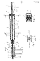
- the two diametrically opposite rotor blades are combined to form an integral component via a common spar part 2.
- the rotor blades 1 and the associated spar part 2 are made of fiber-reinforced plastic with fiber strands extending in the longitudinal direction of the blade, which run from the blade tip of one rotor blade to the blade tip of the other rotor blade for each component or pair of rotor blades and in the area between the two blade blades 1.1 the common, one-piece one Form spar part 2.
- the common spar part 2 is torsionally soft both with respect to the blade angle movements and flexible with respect to the blade stroke and blade pivoting movements. No separate mechanical joints are required for these leaf movements.
- the common spar part 2 of the respective rotor blade pair is clamped immovably in the rotor head 3, for example by means of a screw connection 4 with the rotor shaft 5 with the interposition of fiber-reinforced (rigid) plastic plates 3.1 a respective section of the spar between the rotor head 3 and the adjoining blade wing 1.1, for example also provided with a rigid support 6 consisting of fiber-reinforced synthetic material.
- this envelope-like carrier 6 has the function of limiting the rotor head 3 or the spar part clamping there relative to a flexible region 2.1 of the spar part 2.
- the rigid support 6 is rigidly connected to the spar part 2 at the point determined by the respectively desired length of the flexible spar portion 2.1, for example via a screw connection with the interposition of two fiber-reinforced plastic layers 6.1, and extends to the adjoining leaf wing 1.1 or one here also made with the spar part connection.
- This second blade wing-side connection by means of a radial elastomer bearing 7 is (consequently), in contrast to the first rotor head soapy connection between the carrier 6 and the spar part 2 (by means of the stiff plastic layers 6.1), only stiff in the radial direction.
- the carrier 6 is also intended to function as a bridge with respect to an area 2.2 created in that bending-stiffened spar part area of much higher torsional softness than the released flexible area 2.1.
- this blade-wing-side section 2.2 which is softer in terms of torsion, is kept free by the carrier 6 of any moments from the leaf bend and leaf pivoting bending, while, on the other hand, due to the higher torsion-softness of this section, section 2.2, that of the carrier 6 up to the rotor head 3 or There, the flexible part of the spar part 2.1 released by the blade angle adjustment movements is practically released table remains unaffected, but transmits the leaf impact and leaf swivel bending moments to the rotor head 3.
- this section of the spar section 2.2 can be split into individual strands 2.2.1, preferably by splitting by means of two longitudinal gaps 2.2.2 in the two longitudinal center planes of the section of the section spar.
- the longitudinal gaps 2.2.2 will be expedient - also under the criterion of optimal torsional softness of the spar partial region 2.2 - such that twisting of the strands 2.2.1 (as a result of a blade angle adjustment) prevents mutual contact.
- the spar part 2 is continuous from one blade wing 1.1 to the other (not shown) blade wing (of the second rotor blade) split into individual strands and, with the exception of the highly torsion-soft desired section of the spar 2.2, is stiffened in the longitudinal gaps between the strands 2.2.1 by filling material / 2.2.3.
- the carrier 6, which is free from the centrifugal force of the leaf relative to the spar part 2, can at least approximately have the shape of a shell of the spar part 2 for aerodynamic reasons.
- this (carrier) sleeve would be designed to be continuously open on one of its two longitudinal sides perpendicular to the rotor plane, in order to be able to place it laterally on the spar part 2.
- a design of the support 6 that is open on both sides, according to FIG. 2 only in the area between its two connections with the spar part 2, will have an advantageous effect under the criterion of reduced control forces for the collective blade angle adjustment.
- the blade control lever can be a component of the respective rotor blade 1, for example via a connection on the one hand to the blade wing 1.1 and on the other hand, rotatably movable in angle, with the rigid support 6.
Landscapes
- Engineering & Computer Science (AREA)
- Mechanical Engineering (AREA)
- Aviation & Aerospace Engineering (AREA)
- Life Sciences & Earth Sciences (AREA)
- Sustainable Development (AREA)
- Sustainable Energy (AREA)
- Chemical & Material Sciences (AREA)
- Combustion & Propulsion (AREA)
- General Engineering & Computer Science (AREA)
- Wind Motors (AREA)
- Turbine Rotor Nozzle Sealing (AREA)
- Toys (AREA)
Applications Claiming Priority (2)
| Application Number | Priority Date | Filing Date | Title |
|---|---|---|---|
| DE2903524 | 1979-01-31 | ||
| DE2903524A DE2903524C2 (de) | 1979-01-31 | 1979-01-31 | Schlag- und schwenkgelenkloser Anschluß von Rotorblättern eines Drehflügelflugzeuges |
Publications (2)
| Publication Number | Publication Date |
|---|---|
| EP0014748A2 true EP0014748A2 (fr) | 1980-09-03 |
| EP0014748A3 EP0014748A3 (fr) | 1981-07-01 |
Family
ID=6061746
Family Applications (1)
| Application Number | Title | Priority Date | Filing Date |
|---|---|---|---|
| EP79104686A Withdrawn EP0014748A3 (fr) | 1979-01-31 | 1979-11-24 | Connection non-articulée de pales de rotor pour avion à ailes rotatives |
Country Status (4)
| Country | Link |
|---|---|
| US (1) | US4345876A (fr) |
| EP (1) | EP0014748A3 (fr) |
| JP (1) | JPS55102799A (fr) |
| DE (1) | DE2903524C2 (fr) |
Cited By (1)
| Publication number | Priority date | Publication date | Assignee | Title |
|---|---|---|---|---|
| EP0033771A3 (en) * | 1980-02-07 | 1982-01-20 | Messerschmitt-Bolkow-Blohm Gesellschaft Mit Beschrankter Haftung | Elastomeric damping device |
Families Citing this family (22)
| Publication number | Priority date | Publication date | Assignee | Title |
|---|---|---|---|---|
| US4427340A (en) | 1982-06-24 | 1984-01-24 | Bell Helicopter Textron Inc. | Soft inplane bearingless helicopter rotor |
| US4543040A (en) * | 1982-09-30 | 1985-09-24 | The Boeing Company | Helicopter rotor system |
| DE3241754C2 (de) * | 1982-11-11 | 1986-02-06 | Messerschmitt-Bölkow-Blohm GmbH, 8000 München | Rotor, insbesondere eines Drehflügelflugzeuges |
| US4568246A (en) * | 1983-03-22 | 1986-02-04 | United Technologies Corporation | Fiber reinforced/epoxy matrix composite helicopter rotor torque tube |
| US4585393A (en) * | 1983-03-22 | 1986-04-29 | United Technologies Corporation | Fiber reinforced/epoxy matrix composite helicopter rotor yoke |
| US4568245A (en) * | 1983-03-22 | 1986-02-04 | United Technologies Corporation | Composite helicopter rotor hub |
| DE3464036D1 (en) * | 1983-08-22 | 1987-07-09 | Westland Plc | Helicopter rotors |
| DE3332417C2 (de) * | 1983-09-08 | 1986-04-03 | Messerschmitt-Bölkow-Blohm GmbH, 8012 Ottobrunn | Rotor, insbesondere für Drehflügelflugzeuge |
| DE3401737A1 (de) * | 1984-01-19 | 1985-07-25 | Messerschmitt-Bölkow-Blohm GmbH, 8012 Ottobrunn | Rotor, insbesondere eines drehfluegelflugzeuges |
| GB2165333A (en) * | 1984-09-26 | 1986-04-09 | Steven Odobasic | Laminated torsion elements |
| GB2165026A (en) * | 1984-09-26 | 1986-04-03 | Jose A Avila | Composite torsion link |
| ES2014235B3 (es) * | 1985-10-15 | 1990-07-01 | Westland Group Plc | Rotor de helicoptero. |
| NL8602097A (nl) * | 1986-08-18 | 1988-03-16 | Strijense Kunststof Technieken | Windturbinerotor met twee rotorbladen. |
| GB8922338D0 (en) * | 1989-10-04 | 1989-11-22 | Westland Helicopters | Helicopter rotors |
| DE9201280U1 (de) * | 1992-02-03 | 1992-05-21 | Sperl, Guido, Dipl.-Ing.(FH), 8203 Niederaudorf | Rotor, Propeller bzw. Windrad mit einer beliebigen Anzahl von Blättern mit Biege-/Drillelementen |
| FR2699497B1 (fr) * | 1992-12-23 | 1995-03-10 | Eurocopter France | Dispositif de liaison pale-moyeu à attache feuilletée, pale de rotor munie d'une telle attache, et rotor équipé de telles pales. |
| US6155784A (en) * | 1997-01-09 | 2000-12-05 | Cartercopters, Llc. | Variable pitch aircraft propeller |
| US6024325A (en) * | 1997-01-09 | 2000-02-15 | Cartercopters, Llc | Rotor for rotary wing aircraft |
| DE19701403C1 (de) * | 1997-01-17 | 1998-02-26 | Eurocopter Deutschland | Mehrblattrotor für ein Drehflügelflugzeug |
| US9884680B2 (en) | 2008-12-11 | 2018-02-06 | Sikorsky Aircraft Corporation | Elastomeric bearing system motion limiter |
| DE102010039705B4 (de) * | 2010-08-24 | 2020-02-27 | Airbus Operations Gmbh | Strukturelement für ein Luft- und Raumfahrzeug und Verfahren zum Herstellen eines derartigen Strukturelementes |
| US10059438B2 (en) * | 2011-12-26 | 2018-08-28 | Textron Innovations Inc. | Hub assembly with grease lubricated roller bearing and tension-torsion strap |
Family Cites Families (16)
| Publication number | Priority date | Publication date | Assignee | Title |
|---|---|---|---|---|
| US3026942A (en) * | 1959-07-07 | 1962-03-27 | Bell Helicopter Corp | Helicopter rotor system |
| US3261407A (en) * | 1964-08-05 | 1966-07-19 | Lockheed Aircraft Corp | Helicopter rotor system |
| DE1531374A1 (de) * | 1967-09-12 | 1970-01-29 | Messerschmitt Boelkow Blohm | Rotorblatt aus faserverstaerktem Kunststoff mit schlaufenartiger Blattwurzel |
| US3880551A (en) * | 1973-11-15 | 1975-04-29 | Boeing Co | Rotary head assembly for rotary wing aircraft |
| US3885887A (en) * | 1973-12-05 | 1975-05-27 | Boeing Co | Flexure for bearingless rotor |
| FR2285298A1 (fr) * | 1974-09-19 | 1976-04-16 | Aerospatiale | Agencement de rotor de queue pour giravions |
| US3999887A (en) * | 1975-07-09 | 1976-12-28 | Lord Corporation | Propeller assembly |
| DE2656296C3 (de) * | 1976-12-11 | 1980-10-16 | Messerschmitt-Boelkow-Blohm Gmbh, 8000 Muenchen | Rotor für ein Drehflügelflugzeug |
| US4093400A (en) * | 1976-12-15 | 1978-06-06 | United Technologies Corporation | Cross beam rotor |
| US4087203A (en) * | 1977-01-07 | 1978-05-02 | United Technologies Corporation | Cross beam rotor |
| DE2701519C3 (de) * | 1977-01-15 | 1980-11-20 | Messerschmitt-Boelkow-Blohm Gmbh, 8000 Muenchen | Rotor für ein Drehflügelflugzeug |
| FR2397325A1 (fr) * | 1977-07-13 | 1979-02-09 | Aerospatiale | Moyeu de rotor, en particulier pour le rotor principal d'un helicoptere |
| FR2397326A2 (fr) * | 1977-07-13 | 1979-02-09 | Aerospatiale | Rotor sans articulations, en particulier pour un giravion |
| FR2397327A1 (fr) * | 1977-07-13 | 1979-02-09 | Aerospatiale | Rotor a pas variable, en particulier pour un giravion |
| DE2753305C3 (de) * | 1977-11-30 | 1980-06-12 | Messerschmitt-Boelkow-Blohm Gmbh, 8000 Muenchen | Vierblattrotor, insbesondere fur Drehflügelflugzeuge |
| US4244677A (en) * | 1978-07-12 | 1981-01-13 | United Technologies Corporation | Cross-beam helicopter rotor with readily replaceable snubber |
-
1979
- 1979-01-31 DE DE2903524A patent/DE2903524C2/de not_active Expired
- 1979-11-24 EP EP79104686A patent/EP0014748A3/fr not_active Withdrawn
-
1980
- 1980-01-21 US US06/114,236 patent/US4345876A/en not_active Expired - Lifetime
- 1980-01-31 JP JP949780A patent/JPS55102799A/ja active Pending
Cited By (1)
| Publication number | Priority date | Publication date | Assignee | Title |
|---|---|---|---|---|
| EP0033771A3 (en) * | 1980-02-07 | 1982-01-20 | Messerschmitt-Bolkow-Blohm Gesellschaft Mit Beschrankter Haftung | Elastomeric damping device |
Also Published As
| Publication number | Publication date |
|---|---|
| EP0014748A3 (fr) | 1981-07-01 |
| US4345876A (en) | 1982-08-24 |
| DE2903524A1 (de) | 1980-08-14 |
| DE2903524C2 (de) | 1982-02-25 |
| JPS55102799A (en) | 1980-08-06 |
Similar Documents
| Publication | Publication Date | Title |
|---|---|---|
| EP0014748A2 (fr) | Connection non-articulée de pales de rotor pour avion à ailes rotatives | |
| DE2922469C2 (de) | Rotor für ein Drehflügelflugzeug | |
| DE2829605C2 (de) | Rotornabe | |
| EP0034210B1 (fr) | Rotor d'hélicoptère | |
| EP0019041B1 (fr) | Rotor non-articulé | |
| DE2949156A1 (de) | Hubschrauberrotor | |
| DE2755557A1 (de) | Hubschrauberrotor | |
| DE3633346C1 (de) | Rotor,insbesondere eines Drehfluegelfluegzeuges | |
| DE2919684C3 (de) | Schlag-, schwenk-und blattverstellgelenkloser Rotor | |
| EP0351577B1 (fr) | Rotor, en particulier pour un avion à voilure tournante | |
| DE2611245A1 (de) | Rotor fuer drehfluegelflugzeuge | |
| DE2733101B2 (de) | Schlag- und schwenkgelenklose Rotorblattlagerung | |
| DE2932441C2 (de) | Dämpfungseinrichtung für ein Rotorblatt | |
| DE2214262A1 (de) | Drehflügelanordnung | |
| DE2638167C3 (de) | Rotor für Drehflügelflugzeuge | |
| EP0085129A1 (fr) | Rotor, en particulier pour aéronef à voilure tournante | |
| DE69509732T2 (de) | Gelenkloser Rotor mit Zwischenringen für die Steuerung der Blattverstellung | |
| EP0067952A1 (fr) | Rotor avec jonction pale-moyen, ayant une pied de pale flexible permettant les mouvements de torsion, de trainée et de battement | |
| DE19837802C1 (de) | Rotorblatt für einen lagerlosen Rotor eines Hubschraubers | |
| DE3148903A1 (de) | Rotorblatt mit einer elastomeren daempfungseinrichtung | |
| DE3707333A1 (de) | Rotor, insbesondere eines drehfluegelflugzeugs | |
| DE2701519C3 (de) | Rotor für ein Drehflügelflugzeug | |
| DE102013111114A1 (de) | Rotorsteuervorrichtung mit Taumelscheibeninnenringmitnehmer | |
| DE1531375C3 (de) | Schlag- und schwenkgelenkloser, aber nicht starrer Rotor | |
| EP0141017B1 (fr) | Rotor, en particulier pour un aéronef à voilure tournante |
Legal Events
| Date | Code | Title | Description |
|---|---|---|---|
| AK | Designated contracting states |
Designated state(s): AT BE CH FR GB IT LU NL SE |
|
| PUAI | Public reference made under article 153(3) epc to a published international application that has entered the european phase |
Free format text: ORIGINAL CODE: 0009012 |
|
| AK | Designated contracting states |
Designated state(s): FR GB IT |
|
| PUAL | Search report despatched |
Free format text: ORIGINAL CODE: 0009013 |
|
| RHK1 | Main classification (correction) |
Ipc: B64C 27/34 |
|
| AK | Designated contracting states |
Designated state(s): FR GB IT |
|
| 17P | Request for examination filed |
Effective date: 19810623 |
|
| STAA | Information on the status of an ep patent application or granted ep patent |
Free format text: STATUS: THE APPLICATION HAS BEEN WITHDRAWN |
|
| 18W | Application withdrawn |
Withdrawal date: 19821204 |
|
| RIN1 | Information on inventor provided before grant (corrected) |
Inventor name: STEPHAN, MICHAEL Inventor name: SCHWARZ, ALOIS Inventor name: MAUTZ, KARL-HEINZ |