EP0014818A1 - Verfahren zur Herstellung einer Vorrichtung zum Messen der Temperatur - Google Patents
Verfahren zur Herstellung einer Vorrichtung zum Messen der Temperatur Download PDFInfo
- Publication number
- EP0014818A1 EP0014818A1 EP79850112A EP79850112A EP0014818A1 EP 0014818 A1 EP0014818 A1 EP 0014818A1 EP 79850112 A EP79850112 A EP 79850112A EP 79850112 A EP79850112 A EP 79850112A EP 0014818 A1 EP0014818 A1 EP 0014818A1
- Authority
- EP
- European Patent Office
- Prior art keywords
- temperature
- sensors
- sensor
- electric
- electric lines
- Prior art date
- Legal status (The legal status is an assumption and is not a legal conclusion. Google has not performed a legal analysis and makes no representation as to the accuracy of the status listed.)
- Granted
Links
- 238000000034 method Methods 0.000 title claims abstract description 15
- 230000008878 coupling Effects 0.000 claims abstract description 5
- 238000010168 coupling process Methods 0.000 claims abstract description 5
- 238000005859 coupling reaction Methods 0.000 claims abstract description 5
- 238000005259 measurement Methods 0.000 claims description 3
- 238000007689 inspection Methods 0.000 claims 1
- 238000004519 manufacturing process Methods 0.000 description 7
- 239000000463 material Substances 0.000 description 7
- RYGMFSIKBFXOCR-UHFFFAOYSA-N Copper Chemical compound [Cu] RYGMFSIKBFXOCR-UHFFFAOYSA-N 0.000 description 4
- 239000011889 copper foil Substances 0.000 description 3
- 238000009966 trimming Methods 0.000 description 3
- 238000009529 body temperature measurement Methods 0.000 description 2
- 239000004033 plastic Substances 0.000 description 2
- 229920003023 plastic Polymers 0.000 description 2
- 238000007789 sealing Methods 0.000 description 2
- 241001424392 Lucia limbaria Species 0.000 description 1
- 239000000853 adhesive Substances 0.000 description 1
- 230000001070 adhesive effect Effects 0.000 description 1
- 239000011230 binding agent Substances 0.000 description 1
- 230000015572 biosynthetic process Effects 0.000 description 1
- 238000007757 hot melt coating Methods 0.000 description 1
- 239000012943 hotmelt Substances 0.000 description 1
- 238000009413 insulation Methods 0.000 description 1
- 238000004080 punching Methods 0.000 description 1
- 230000001360 synchronised effect Effects 0.000 description 1
Images
Classifications
-
- G—PHYSICS
- G01—MEASURING; TESTING
- G01K—MEASURING TEMPERATURE; MEASURING QUANTITY OF HEAT; THERMALLY-SENSITIVE ELEMENTS NOT OTHERWISE PROVIDED FOR
- G01K7/00—Measuring temperature based on the use of electric or magnetic elements directly sensitive to heat ; Power supply therefor, e.g. using thermoelectric elements
- G01K7/16—Measuring temperature based on the use of electric or magnetic elements directly sensitive to heat ; Power supply therefor, e.g. using thermoelectric elements using resistive elements
- G01K7/22—Measuring temperature based on the use of electric or magnetic elements directly sensitive to heat ; Power supply therefor, e.g. using thermoelectric elements using resistive elements the element being a non-linear resistance, e.g. thermistor
- G01K7/223—Measuring temperature based on the use of electric or magnetic elements directly sensitive to heat ; Power supply therefor, e.g. using thermoelectric elements using resistive elements the element being a non-linear resistance, e.g. thermistor characterised by the shape of the resistive element
-
- G—PHYSICS
- G01—MEASURING; TESTING
- G01K—MEASURING TEMPERATURE; MEASURING QUANTITY OF HEAT; THERMALLY-SENSITIVE ELEMENTS NOT OTHERWISE PROVIDED FOR
- G01K13/00—Thermometers specially adapted for specific purposes
- G01K13/20—Clinical contact thermometers for use with humans or animals
Definitions
- the present invention relates to an apparatus for measuring temperature, comprising a temperature-sensitive preferably untrimmed sensor whose electric properties, for example, resistance, vary with the temperature, for example, a thermistor which is connected to two electric lines which, in turn, may bo connected to a read-off unit for reading off the values of current, voltage or the like corresponding to the temperature.
- a temperature-sensitive preferably untrimmed sensor whose electric properties, for example, resistance, vary with the temperature
- a thermistor which is connected to two electric lines which, in turn, may bo connected to a read-off unit for reading off the values of current, voltage or the like corresponding to the temperature.
- the apparatus according to the invention is primarily intended to use in medicinal temperature measurement.
- One aspect of the invention is, therefore, to make it so simple and economical that it may be disposed of after use, that is to say that it need not be reused.
- Swedish Patent Application 28.03046-7 U.S. Serial No. 779 152
- the two PCT Applications PCT/SE78/00012 and PCT/SE78/00013 describe different embodiments of an apparatus similar to that according to the invention and how the apparatus according t the invention may be used.
- the concept forming the basis of the present invention is, in this instance, int. al. to realize such an apparatus but of simpler type and adapted to a simpler manner of manufacture.
- the primary object of the present invention is to replace these relatively complicated trimming processes with a simple sorting process and subsequent combination of two or more sensors.
- the apparatus according to the invention is characterized by one or more further preferably untrimmed sensors which, together with the first-mentioned sensor, are selected and coupled such that they, at least within a determined temperature range, have a value of the above-mentioned electric property accurately corresponding to the temperature.
- the sensors are connected in series between the two electric lines and are selected such that the sum of their deviations from certain determined values have a predetermined value, for example, zero.
- the invention also relates to a method of producing the above-described apparatus.
- This method is characterized in that the above-mentioned electric property for a large number of sensors is measured, the property forming the basis of a sorting within carefully determined intervals, whereafter two or more sensors are selected for each apparatus, the sensors, on the desired coupling to the electric lines, giving a desired value of the above-mentioned electric property.
- the above-mentioned sensors are suitably constituted of two thermistors, fixedly disposed on a copper foil which will be described in greater detail in the following discussion under the title "Preferred embodiment of the invention".
- Sorting of these thermistors is, in this case, suitably effected in a temperature chamber whose temperature is stabilized at, for example, 38°C - 0.5°C or, if possible, better.
- Measurement of the resistance of the sample may be effected with a current of 300 pA, which gives a power consumption in the component of approximately 270 ⁇ W, which is so low that the temperature is not appreciably elevated.
- thermistors with resistance of 3000 ⁇ in compartments whose width is 0.5% (15 ⁇ ). These thermistors are then paired together in series coupling so that their respective resistances are added.
- a resistance of 6000 ⁇ can, for example, be obtained by two resistances of 3105 and 2895 or by two resistances of precisely 3000 ⁇ .
- substantially all thermistors can be utilized, that is to say with an effective level of 100%.
- Mounting may then be effected in that one thermistor from each respective batch is placed, by means of two vacuum pincettes, on a small copper foil piece and are fixedly welded thereto.
- the two thermistors may then be considered as a sensor, as is also the case in the following description, in the same manner as the description in co-filed Patent Application P CT/SE79/00018.
- the thermistors may be coupled in parallel, utilizing the formula . If, in this situation, a resistance of 6000 ⁇ is desired, this may be attained by a parallel coupling of, for example, one resistance of 12100.0 ⁇ and one of 11901.6 ⁇ .
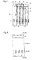
- Fi g . 6 shows one of the material layers used in the manufacture according to Fig. 5.
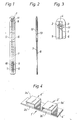
- the apparatus shown by way of example comprises, thus, a temperature-sensitive sensor which in its entirety is designated 1 in Figs. land 3 and 1', respectively, in Fig. 4.
- this sensor consists according to Figs. 1-3 of two thermistors 2 and 3 which are interconnected via an intermediate line 4.
- Each one of these thermistors constitutes, thus, a sensor in the sense that this word is used in the claims, at the same time as they form, in their entirety, one sensor, as will be apparent from the following discussion.
- the thermistors are, instead, designated 2' and 3', respectively, whereas the intermediate line consists of a copper foil designated 4'.
- the terminals of the one thermistor are designated 2a' and 2b', whereas the terminals of the second thermistor are designated 3a' and 3b'.
- the two thermistors 2 and 3 are connected to electric lines 5 and 6, respectively.
- the corresponding lines are connected to the terminals 2a' and 3a'.
- the electric lines 5 and 6 are encapsulated between two inner, insulating layers 7 and 8 which present mutually offset holes 9 and 10, respectively, each in register with their respective line 6 and 5, respectively. As a result, these lines 6 and 5 are disposed through the holes 9 and 10.
- the two insulating layers 7 and 8 suitably consist of plastics-coated paper, which facilitates manufacture, since heat sealing may be used to unite the two layers with each other and with other materials. At the same time, use is made possible of the apparatus according to the invention in a humide environment.
- the two insulating layers 7 and 8 present, furthermore, holes 11 in register with each other and with the sensor.
- the sensor 1 and the holes 11 in register therewith are covered by two insulating, outer layers 12 and 13. These outer layers are provided only along the forward end of the apparatus and do not, thus, cover the holes 9 and 10.
- the two electric lines 5 and 6 are of substantially the same length as the two elongate insulating layers 7 and 8, between which they are located, the sensor 1 being located proximal to one end which, as above and as in the following discussion, is designated the forward end of the apparatus, whereas the mutually offset holes 9 and 10 are located proximal the opposite end of the insulating layers.
- the two insulating, outer layers 12 and 13 extend out over the forward end of the two inner, insulating layers such that they also insulate the ends of the lines 5 and 6 located therebetween. As a result, this forward end may be rounded-off without exposing these lines.
- a composed sensor is produced consisting of two thermistors by means of sorting and combination as described above under the title "Sorting of sensors”.
- One line 14 for example, a thin copper wire, is led in zig-zag formation between two paper webs 7c and 8c. These webs are synchronously led through punched holes 15, 16, 17 and 18 which, for example, may run over sprockets or the like. Both of the webs are provided with holes 11 which, as a result of the synchronous advancement, will be located in register with each other. In register with the holes 11, the lines 5 and 6 formed by the wire 14 are also exposed, the sensor 1 being connected thereto. Therafter, the two outer edge portions of the webs 7c and 8c with the holes 15, 16, 17 and 18 may be cut off.
- Fig. 5 the manufacturing process is illustrated, naturally, schematically and in a highly concentrated state.
- the different manufacturing operations are effected by means of separate apparatuses in completely separate processes, for exaniple, in separate stations along a longer material web which is constructed gradually.
- Fig. 6 shows a material web which may constitute either of the material webs 7c and 8c which differ from each other only by the placing of the holes 9 and 10, respectively.
- the holes 17 and 18, and 15 and 16, respectively are identical, at the same time as both webs contain holes 11.
- plastics-coated paper layers 7 and 8 may be replaced by layers of waxed paper with, for example, a hotmelt coating on one side for the joining-together process.
- they may be replaced by normal paper without moisture insulation, since this may be realized by means of the outer layers 12 and 13.
- the sealing may be produced by means of a hotmelt, adhesive or other suitable binder.
Landscapes
- Physics & Mathematics (AREA)
- General Physics & Mathematics (AREA)
- Nonlinear Science (AREA)
- Measuring Temperature Or Quantity Of Heat (AREA)
- Thermistors And Varistors (AREA)
- Crystals, And After-Treatments Of Crystals (AREA)
- Joints Allowing Movement (AREA)
- Measuring Fluid Pressure (AREA)
- Extrusion Moulding Of Plastics Or The Like (AREA)
- Blow-Moulding Or Thermoforming Of Plastics Or The Like (AREA)
- Electrical Discharge Machining, Electrochemical Machining, And Combined Machining (AREA)
- Cookers (AREA)
Priority Applications (1)
| Application Number | Priority Date | Filing Date | Title |
|---|---|---|---|
| AT79850112T ATE7079T1 (de) | 1979-01-25 | 1979-12-18 | Verfahren zur herstellung einer vorrichtung zum messen der temperatur. |
Applications Claiming Priority (2)
| Application Number | Priority Date | Filing Date | Title |
|---|---|---|---|
| SE7900673A SE436660B (sv) | 1979-01-25 | 1979-01-25 | Anordning for metning av temperatur och sett att astadkomma en anordning for metning av temperatur |
| SE7900673 | 1979-01-25 |
Publications (2)
| Publication Number | Publication Date |
|---|---|
| EP0014818A1 true EP0014818A1 (de) | 1980-09-03 |
| EP0014818B1 EP0014818B1 (de) | 1984-04-11 |
Family
ID=20337106
Family Applications (1)
| Application Number | Title | Priority Date | Filing Date |
|---|---|---|---|
| EP79850112A Expired EP0014818B1 (de) | 1979-01-25 | 1979-12-18 | Verfahren zur Herstellung einer Vorrichtung zum Messen der Temperatur |
Country Status (16)
| Country | Link |
|---|---|
| US (1) | US4302972A (de) |
| EP (1) | EP0014818B1 (de) |
| JP (1) | JPS55101834A (de) |
| AT (1) | ATE7079T1 (de) |
| AU (1) | AU533519B2 (de) |
| BR (1) | BR8000386A (de) |
| CA (1) | CA1128337A (de) |
| DE (2) | DE2966899D1 (de) |
| DK (1) | DK149237C (de) |
| ES (2) | ES487424A1 (de) |
| FI (1) | FI70645C (de) |
| GR (1) | GR73173B (de) |
| IE (1) | IE48713B1 (de) |
| MX (1) | MX148077A (de) |
| NO (1) | NO155265C (de) |
| SE (1) | SE436660B (de) |
Cited By (5)
| Publication number | Priority date | Publication date | Assignee | Title |
|---|---|---|---|---|
| EP0063295A3 (en) * | 1981-04-15 | 1983-06-22 | Gambro Crafon Aktiebolag | Method for producing thermistors, thermistors produced by this method as well as thermometers containing such thermistors |
| EP0080768A3 (en) * | 1981-11-26 | 1985-09-25 | Philips Patentverwaltung Gmbh | Temperature sensor |
| EP0213239A1 (de) * | 1985-07-29 | 1987-03-11 | Milton Schonberger | Wegwerfthermometerfühler und Kalibrierungstechnik für denselben |
| WO1990010854A1 (en) * | 1989-03-08 | 1990-09-20 | Isis Innovation Limited | Thermometer |
| FR2703182A1 (fr) * | 1993-03-22 | 1994-09-30 | Murata Manufacturing Co | Procédé pour fournir des thermistances à coefficient de température positif et jeu de thermistances à coefficient de température positif fourni grâce à ce procédé. |
Families Citing this family (8)
| Publication number | Priority date | Publication date | Assignee | Title |
|---|---|---|---|---|
| US4382246A (en) * | 1980-09-25 | 1983-05-03 | Crafon Medical Ab | Apparatus for measuring temperature |
| US4507854A (en) * | 1980-09-25 | 1985-04-02 | Gambro Crafon Ab | Method of manufacturing temperature-sensitive instruments |
| JP2675344B2 (ja) * | 1988-08-25 | 1997-11-12 | テルモ株式会社 | 測温用プローブ |
| EP2155300A1 (de) | 2007-04-05 | 2010-02-24 | Velomedix, Inc | Automatisches therapiesystem und verfahren |
| CA2693774A1 (en) | 2007-07-09 | 2009-01-15 | Velomedix, Inc. | Hypothermia devices and methods |
| CN101609978A (zh) * | 2008-06-20 | 2009-12-23 | 鸿富锦精密工业(深圳)有限公司 | 电池过热保护装置和方法 |
| US9622670B2 (en) | 2010-07-09 | 2017-04-18 | Potrero Medical, Inc. | Method and apparatus for pressure measurement |
| EP2668479A2 (de) * | 2011-01-26 | 2013-12-04 | Velomedix, Inc. | Redundanter doppelter temperatursensor für einen thermistor |
Citations (1)
| Publication number | Priority date | Publication date | Assignee | Title |
|---|---|---|---|---|
| US3109227A (en) * | 1962-11-05 | 1963-11-05 | Fenwal Electronics Inc | Uniform thermistor manufacture |
Family Cites Families (8)
| Publication number | Priority date | Publication date | Assignee | Title |
|---|---|---|---|---|
| US3028756A (en) * | 1960-07-26 | 1962-04-10 | Takagishi Eijiro | Resistance networks with thermistors |
| US3110088A (en) * | 1962-04-06 | 1963-11-12 | Specialties Dev Corp | Method of making resistance elements |
| US3673538A (en) * | 1969-12-05 | 1972-06-27 | Texas Instruments Inc | Composite thermistor temperature sensor having step-function response |
| US3684996A (en) * | 1970-04-13 | 1972-08-15 | Barnes Eng Co | High-sensitivity, long-time-constant thermistor bolometer |
| FR2105486A5 (de) * | 1970-09-09 | 1972-04-28 | Electro Resistance | |
| US3750471A (en) * | 1971-03-04 | 1973-08-07 | N Bremer | Bifurcated thermometer probe |
| US3889362A (en) * | 1973-10-29 | 1975-06-17 | Robertshaw Controls Co | Method of making electrical resistance element |
| JPS52153483A (en) * | 1976-06-15 | 1977-12-20 | Matsushita Electric Works Ltd | Temperature detector |
-
1979
- 1979-01-25 SE SE7900673A patent/SE436660B/sv not_active IP Right Cessation
- 1979-06-01 US US06/044,387 patent/US4302972A/en not_active Expired - Lifetime
- 1979-12-04 IE IE2325/79A patent/IE48713B1/en not_active IP Right Cessation
- 1979-12-13 GR GR60747A patent/GR73173B/el unknown
- 1979-12-18 DE DE7979850112T patent/DE2966899D1/de not_active Expired
- 1979-12-18 EP EP79850112A patent/EP0014818B1/de not_active Expired
- 1979-12-18 AT AT79850112T patent/ATE7079T1/de not_active IP Right Cessation
- 1979-12-20 NO NO794188A patent/NO155265C/no unknown
-
1980
- 1980-01-03 ES ES487424A patent/ES487424A1/es not_active Expired
- 1980-01-03 ES ES487420A patent/ES487420A1/es not_active Expired
- 1980-01-14 FI FI800102A patent/FI70645C/fi not_active IP Right Cessation
- 1980-01-22 BR BR8000386A patent/BR8000386A/pt not_active IP Right Cessation
- 1980-01-23 CA CA344,288A patent/CA1128337A/en not_active Expired
- 1980-01-23 JP JP675180A patent/JPS55101834A/ja active Pending
- 1980-01-23 DE DE19808001678U patent/DE8001678U1/de not_active Expired
- 1980-01-23 MX MX180921A patent/MX148077A/es unknown
- 1980-01-23 DK DK28280A patent/DK149237C/da not_active IP Right Cessation
- 1980-01-24 AU AU54900/80A patent/AU533519B2/en not_active Expired
Patent Citations (1)
| Publication number | Priority date | Publication date | Assignee | Title |
|---|---|---|---|---|
| US3109227A (en) * | 1962-11-05 | 1963-11-05 | Fenwal Electronics Inc | Uniform thermistor manufacture |
Cited By (6)
| Publication number | Priority date | Publication date | Assignee | Title |
|---|---|---|---|---|
| EP0063295A3 (en) * | 1981-04-15 | 1983-06-22 | Gambro Crafon Aktiebolag | Method for producing thermistors, thermistors produced by this method as well as thermometers containing such thermistors |
| EP0080768A3 (en) * | 1981-11-26 | 1985-09-25 | Philips Patentverwaltung Gmbh | Temperature sensor |
| EP0213239A1 (de) * | 1985-07-29 | 1987-03-11 | Milton Schonberger | Wegwerfthermometerfühler und Kalibrierungstechnik für denselben |
| WO1990010854A1 (en) * | 1989-03-08 | 1990-09-20 | Isis Innovation Limited | Thermometer |
| FR2703182A1 (fr) * | 1993-03-22 | 1994-09-30 | Murata Manufacturing Co | Procédé pour fournir des thermistances à coefficient de température positif et jeu de thermistances à coefficient de température positif fourni grâce à ce procédé. |
| US5686830A (en) * | 1993-03-22 | 1997-11-11 | Muarata Manufacturing Co., Ltd. | Method of supplying positive temperature coefficient thermistor elements to the receiving and transmitting sides of a communication device |
Also Published As
| Publication number | Publication date |
|---|---|
| BR8000386A (pt) | 1980-10-14 |
| FI800102A7 (fi) | 1980-07-26 |
| IE48713B1 (en) | 1985-05-01 |
| GR73173B (de) | 1984-02-14 |
| IE792325L (en) | 1980-07-25 |
| ES487420A1 (es) | 1980-06-16 |
| EP0014818B1 (de) | 1984-04-11 |
| ATE7079T1 (de) | 1984-04-15 |
| AU533519B2 (en) | 1983-12-01 |
| MX148077A (es) | 1983-03-10 |
| DK28280A (da) | 1980-07-26 |
| JPS55101834A (en) | 1980-08-04 |
| DE2966899D1 (en) | 1984-05-17 |
| DK149237C (da) | 1986-09-22 |
| AU5490080A (en) | 1980-07-31 |
| FI70645B (fi) | 1986-06-06 |
| CA1128337A (en) | 1982-07-27 |
| FI70645C (fi) | 1986-09-24 |
| NO155265C (no) | 1987-03-11 |
| NO794188L (no) | 1980-07-28 |
| DE8001678U1 (de) | 1980-04-17 |
| SE436660B (sv) | 1985-01-14 |
| ES487424A1 (es) | 1980-06-16 |
| NO155265B (no) | 1986-11-24 |
| SE7900673L (sv) | 1980-07-26 |
| US4302972A (en) | 1981-12-01 |
| DK149237B (da) | 1986-04-01 |
Similar Documents
| Publication | Publication Date | Title |
|---|---|---|
| US4302972A (en) | Apparatus for measuring temperature and a method of producing same | |
| US4480376A (en) | Thermistors, their method of production | |
| US4382246A (en) | Apparatus for measuring temperature | |
| CH632842A5 (en) | Temperature sensor for electronic temperature measurements | |
| US4296633A (en) | Device for temperature measurement | |
| EP0026170B1 (de) | Apparat zum messen der temperatur | |
| US4507854A (en) | Method of manufacturing temperature-sensitive instruments | |
| US4349958A (en) | Device for temperature measurement and a method for the manufacture of such a device | |
| US3327271A (en) | Strain gauge | |
| US4617548A (en) | Current sensing resistance apparatus | |
| SE443485B (sv) | Sett att framstella elektroniska komponenter | |
| CA1125537A (en) | Device for temperature measurement and a method for the manufacture of such a device | |
| DE1573374C3 (de) | Folienwärmestrommesser für die Messung von Lokalwerten der Wärmeübergangszahlen und Verfahren zu dessen Herstellung | |
| IE49002B1 (en) | An apparatus for measuring temperature | |
| SU1331437A3 (ru) | Устройство дл измерени температуры | |
| SE421350B (sv) | Anordning for metning av temperatur samt sett att tillverka en sadan anordning | |
| ITMI950914A1 (it) | Procedimento per la produzione di resistori,particolarmente studiati per l'impiego nel settore automobilistico |
Legal Events
| Date | Code | Title | Description |
|---|---|---|---|
| PUAI | Public reference made under article 153(3) epc to a published international application that has entered the european phase |
Free format text: ORIGINAL CODE: 0009012 |
|
| AK | Designated contracting states |
Designated state(s): AT BE CH DE FR GB IT LU NL |
|
| 17P | Request for examination filed |
Effective date: 19810221 |
|
| RAP1 | Party data changed (applicant data changed or rights of an application transferred) |
Owner name: CRAFON MEDICAL AB |
|
| ITF | It: translation for a ep patent filed | ||
| GRAA | (expected) grant |
Free format text: ORIGINAL CODE: 0009210 |
|
| RAP1 | Party data changed (applicant data changed or rights of an application transferred) |
Owner name: GAMBRO CRAFON AKTIEBOLAG |
|
| AK | Designated contracting states |
Designated state(s): AT BE CH DE FR GB IT LU NL |
|
| REF | Corresponds to: |
Ref document number: 7079 Country of ref document: AT Date of ref document: 19840415 Kind code of ref document: T |
|
| REF | Corresponds to: |
Ref document number: 2966899 Country of ref document: DE Date of ref document: 19840517 |
|
| ET | Fr: translation filed | ||
| BECN | Be: change of holder's name |
Effective date: 19840411 |
|
| PLBE | No opposition filed within time limit |
Free format text: ORIGINAL CODE: 0009261 |
|
| STAA | Information on the status of an ep patent application or granted ep patent |
Free format text: STATUS: NO OPPOSITION FILED WITHIN TIME LIMIT |
|
| 26N | No opposition filed | ||
| ITPR | It: changes in ownership of a european patent |
Owner name: CAMBIO RAGIONE SOCIALE;CRAFON AG |
|
| REG | Reference to a national code |
Ref country code: CH Ref legal event code: PFA Free format text: CRAFON AKTIEBOLAG |
|
| REG | Reference to a national code |
Ref country code: FR Ref legal event code: CA |
|
| NLT1 | Nl: modifications of names registered in virtue of documents presented to the patent office pursuant to art. 16 a, paragraph 1 |
Owner name: CRAFON AKTIEBOLAG TE SOEDERTAELJE, ZWEDEN. |
|
| ITTA | It: last paid annual fee | ||
| REG | Reference to a national code |
Ref country code: LU Ref legal event code: CNA Free format text: 3820 16 CRAFON AKTIEBOLAG, C/O AB ASTRA LEGAL DEPARTMENT3820 16 -151 85 SOEDERTAELJE (SUEDE) |
|
| EPTA | Lu: last paid annual fee | ||
| PGFP | Annual fee paid to national office [announced via postgrant information from national office to epo] |
Ref country code: GB Payment date: 19971209 Year of fee payment: 19 Ref country code: FR Payment date: 19971209 Year of fee payment: 19 |
|
| PGFP | Annual fee paid to national office [announced via postgrant information from national office to epo] |
Ref country code: LU Payment date: 19971210 Year of fee payment: 19 |
|
| PGFP | Annual fee paid to national office [announced via postgrant information from national office to epo] |
Ref country code: AT Payment date: 19971212 Year of fee payment: 19 |
|
| PGFP | Annual fee paid to national office [announced via postgrant information from national office to epo] |
Ref country code: NL Payment date: 19971223 Year of fee payment: 19 |
|
| PGFP | Annual fee paid to national office [announced via postgrant information from national office to epo] |
Ref country code: CH Payment date: 19980108 Year of fee payment: 19 |
|
| PGFP | Annual fee paid to national office [announced via postgrant information from national office to epo] |
Ref country code: BE Payment date: 19980217 Year of fee payment: 19 |
|
| PG25 | Lapsed in a contracting state [announced via postgrant information from national office to epo] |
Ref country code: LU Free format text: LAPSE BECAUSE OF NON-PAYMENT OF DUE FEES Effective date: 19981218 Ref country code: GB Free format text: LAPSE BECAUSE OF NON-PAYMENT OF DUE FEES Effective date: 19981218 Ref country code: AT Free format text: LAPSE BECAUSE OF NON-PAYMENT OF DUE FEES Effective date: 19981218 |
|
| PGFP | Annual fee paid to national office [announced via postgrant information from national office to epo] |
Ref country code: DE Payment date: 19981229 Year of fee payment: 20 |
|
| PG25 | Lapsed in a contracting state [announced via postgrant information from national office to epo] |
Ref country code: CH Free format text: LAPSE BECAUSE OF NON-PAYMENT OF DUE FEES Effective date: 19981231 Ref country code: BE Free format text: LAPSE BECAUSE OF NON-PAYMENT OF DUE FEES Effective date: 19981231 |
|
| BERE | Be: lapsed |
Owner name: CRAFON A.B. Effective date: 19981231 |
|
| PG25 | Lapsed in a contracting state [announced via postgrant information from national office to epo] |
Ref country code: NL Free format text: LAPSE BECAUSE OF NON-PAYMENT OF DUE FEES Effective date: 19990701 |
|
| GBPC | Gb: european patent ceased through non-payment of renewal fee |
Effective date: 19981218 |
|
| REG | Reference to a national code |
Ref country code: CH Ref legal event code: PL |
|
| PG25 | Lapsed in a contracting state [announced via postgrant information from national office to epo] |
Ref country code: FR Free format text: LAPSE BECAUSE OF NON-PAYMENT OF DUE FEES Effective date: 19990831 |
|
| NLV4 | Nl: lapsed or anulled due to non-payment of the annual fee |
Effective date: 19990701 |
|
| REG | Reference to a national code |
Ref country code: FR Ref legal event code: ST |