EP0014819A1 - Cathode pour pulvérisation et appareil pour revêtir par pulvérisation cathodique des substrats de grande surface - Google Patents
Cathode pour pulvérisation et appareil pour revêtir par pulvérisation cathodique des substrats de grande surface Download PDFInfo
- Publication number
- EP0014819A1 EP0014819A1 EP79870031A EP79870031A EP0014819A1 EP 0014819 A1 EP0014819 A1 EP 0014819A1 EP 79870031 A EP79870031 A EP 79870031A EP 79870031 A EP79870031 A EP 79870031A EP 0014819 A1 EP0014819 A1 EP 0014819A1
- Authority
- EP
- European Patent Office
- Prior art keywords
- cathode
- target
- extending
- face portions
- target face
- Prior art date
- Legal status (The legal status is an assumption and is not a legal conclusion. Google has not performed a legal analysis and makes no representation as to the accuracy of the status listed.)
- Granted
Links
Images
Classifications
-
- H—ELECTRICITY
- H01—ELECTRIC ELEMENTS
- H01J—ELECTRIC DISCHARGE TUBES OR DISCHARGE LAMPS
- H01J37/00—Discharge tubes with provision for introducing objects or material to be exposed to the discharge, e.g. for the purpose of examination or processing thereof
- H01J37/32—Gas-filled discharge tubes
- H01J37/32431—Constructional details of the reactor
- H01J37/3244—Gas supply means
-
- C—CHEMISTRY; METALLURGY
- C23—COATING METALLIC MATERIAL; COATING MATERIAL WITH METALLIC MATERIAL; CHEMICAL SURFACE TREATMENT; DIFFUSION TREATMENT OF METALLIC MATERIAL; COATING BY VACUUM EVAPORATION, BY SPUTTERING, BY ION IMPLANTATION OR BY CHEMICAL VAPOUR DEPOSITION, IN GENERAL; INHIBITING CORROSION OF METALLIC MATERIAL OR INCRUSTATION IN GENERAL
- C23C—COATING METALLIC MATERIAL; COATING MATERIAL WITH METALLIC MATERIAL; SURFACE TREATMENT OF METALLIC MATERIAL BY DIFFUSION INTO THE SURFACE, BY CHEMICAL CONVERSION OR SUBSTITUTION; COATING BY VACUUM EVAPORATION, BY SPUTTERING, BY ION IMPLANTATION OR BY CHEMICAL VAPOUR DEPOSITION, IN GENERAL
- C23C14/00—Coating by vacuum evaporation, by sputtering or by ion implantation of the coating forming material
- C23C14/22—Coating by vacuum evaporation, by sputtering or by ion implantation of the coating forming material characterised by the process of coating
- C23C14/56—Apparatus specially adapted for continuous coating; Arrangements for maintaining the vacuum, e.g. vacuum locks
-
- H—ELECTRICITY
- H01—ELECTRIC ELEMENTS
- H01J—ELECTRIC DISCHARGE TUBES OR DISCHARGE LAMPS
- H01J37/00—Discharge tubes with provision for introducing objects or material to be exposed to the discharge, e.g. for the purpose of examination or processing thereof
- H01J37/32—Gas-filled discharge tubes
- H01J37/32431—Constructional details of the reactor
- H01J37/32733—Means for moving the material to be treated
- H01J37/32752—Means for moving the material to be treated for moving the material across the discharge
- H01J37/32761—Continuous moving
-
- H—ELECTRICITY
- H01—ELECTRIC ELEMENTS
- H01J—ELECTRIC DISCHARGE TUBES OR DISCHARGE LAMPS
- H01J37/00—Discharge tubes with provision for introducing objects or material to be exposed to the discharge, e.g. for the purpose of examination or processing thereof
- H01J37/32—Gas-filled discharge tubes
- H01J37/32431—Constructional details of the reactor
- H01J37/32733—Means for moving the material to be treated
- H01J37/32752—Means for moving the material to be treated for moving the material across the discharge
- H01J37/32761—Continuous moving
- H01J37/3277—Continuous moving of continuous material
-
- H—ELECTRICITY
- H01—ELECTRIC ELEMENTS
- H01J—ELECTRIC DISCHARGE TUBES OR DISCHARGE LAMPS
- H01J37/00—Discharge tubes with provision for introducing objects or material to be exposed to the discharge, e.g. for the purpose of examination or processing thereof
- H01J37/32—Gas-filled discharge tubes
- H01J37/34—Gas-filled discharge tubes operating with cathodic sputtering
- H01J37/3402—Gas-filled discharge tubes operating with cathodic sputtering using supplementary magnetic fields
- H01J37/3405—Magnetron sputtering
- H01J37/3408—Planar magnetron sputtering
Definitions
- the present invention relates to sputter coating systems and more particularly to sputter coating systems used for high volume production of relatively large size coated products.
- Sputtering is usually accomplished by bombarding a "target" formed from a desired coating material. such as gold, with ions so that individual atoms of the coating material are dislodged from the target and strike and adhere to the substrate.
- a desired coating material such as gold
- the sputtering process is carried out under low pressure conditions (e.g., pressures of from 1 to 50 microns) with the target forming part of a cathode electrode from which electrons are emitted.
- An inert gas, such as Argon is admitted to the vicinity of the cathode where the gas is ionized producing a plasma formed of positively charged gas ions and electrons.
- the ions are accelerated toward the target and strike the target with sufficient energy that target atoms are sputtered onto the substrate.
- Some prior art sputtering systems employed so-called "post" electrodes in that the cathode was formed by an elongated post-like rod, or tube, of target material connected to an negative terminal of a D.C. power supply. Electrons emitted from these electrodes tended to disperse in all directions from the electrode and ionize the gas.
- Efficiency of ionizing the gas was improved by the use of magnetic fields which were oriented to confine emitted electrons in regions close to the target surface.
- This technique known as magnetic enhancement, was carried out by supporting magnets on the cathodes in orientations assuring that emitted electrons were constrained to remain relatively close to the surface of the sputtering target. Confining electrons adjacent the target surface causes increased numbers of collisions between the gas and the electrons thus increasing the ionization efficiency. This tended to reduce the cathode voltage requirements because fewer electrons had to be produced to accomplish a given amount of sputtering. Moreover a smaller quantity of gas could be admitted to the chamber to achieve the same amount .of ionization. This permitted lower operating pressures with less interference between sputtered atoms and gas atoms in th-e enclosure.
- the shape of the magnetically enhanced cathode was such that the sputtering occurred primarily in a given direction.
- the cathode employed a planar target plate having bar magnets supported beneath it in an annular array.
- the fields from these magnets arched over the target surface and collectively defined a "race track", or loop shaped region over the target surface in which the electrons tended to be confined.
- the magnetic fields also induced motion of the electrons in one direction through the region so that a continuous flow of electrons circulated around the track, or loop, in a relatively narrow band adjacent the surface of the target.
- annular target had magnets supported about its outer periphery so that emitted electrons were swept around the inner peripheral face of the target.
- a substrate placed within the target periphery was sputtered from all directions around the target periphery. See, for example, U.S. patent 33878,085.
- Cathodes of the character referred to tended to be eroded along narrow zones in the immediate vicinity of the electron flow path. This reduced the life of the target.
- Targets are frequently constructed from materials which themselves are extremely costly and/or are difficult and expensive to fabricate. Accordingly localized severe target erosion is highly undesirable because it shortens the effective life of the target and requires relatively frequent electrode replacements.
- replacement of electrodes in large enclosures necessitates venting the enclosures to atmosphere for replacement and subsequently pumping the enclosures back down to operating vacuum level. This is a time consuming and expensive interruption of production. Still further because the sputtering occurred over a small target area the sputtering rate was limited , thus limiting the production rate.
- cathodes of the character referred to above was also somewhat ineffective for high volume production of articles such as architectural glass because only one face of one piece of glass could be coated at a time using one electrode. If, for example, two sheets of glass were to be coated simultaneously in order to increase production rates, two of the electrodes would have to be employed.
- a recent proposal has been made for constructing a two sided cathode formed by opposed separate target plates having a single array of magnets supported between them (e.g., as in U.S. Patent 4,116,806). The magnets confine the electrons and ions to continuous loops extending over each target plate.
- the present invention provides a new and improved sputtering system which is so constructed and arranged that substrates on opposite sides of a magnetically enhanced cathode target are simultaneously sputter coated as a result of establishment of a continuous band or belt of plasma which extends over broad target areas adjacent the respective substrates enabling relatively high production rates while increasing sputtering target life and efficiency.
- an evacuable enclosure is provided with a conveyor system along which substrates to be coated are moved on substantially parallel paths.
- a cathode supported between the paths creates the band or belt of plasma having first and second sections extending generally parallel to substrates moving along the respective paths and short return sections between ends of the first and second sections.
- the cathode includes first and second sputtering material faces which respectively extend adjacent and parallel to the first and second plasma belt sections and magnetic field directing structure for confining the plasma belt sections close to and distributed substantially uniformly across the first and second faces.
- the preferred cathode construction includes an elongated electrically conductive support structure connected to an electrical power supply, a sputtering target extending longitudinally of and circumferentially about the support structure , and a magnetic field directing system for confining emitted electrons in the vicinity of and distributed relatively uniformly across the target face.
- the target face is formed by first and second target face portions extending along the length of the supporting structure and facing differing directions. Bridging face portions extend between the target face portions at their opposite ends and across the ends of the electrode.
- the magnetic field directing system includes magnets for producing magnetic fields and magnetic field conducting members, the latter extending longitudinally along the support structure and along respective lateral sides of the target face portions.
- the field conducting members control the magnetic field adjacent the target faces to confine and distribute the plasma close to and over the full area of each target face. Accordingly, erosion due to the sputtering occurs relatively evenly across the target faces.
- the magnets can be of any type but are preferably permanent magnets magnetically coupled to the field conducting members and distributed along the target face to induce movement of emitted electrons about the electrode.
- the field directing members include-magnetically conductive elements which clamp the target faces in place to the electrode. This avoids the necessity for machining the target to provide mounting screw holes, etc. Target materials which are difficult to machine are readily usable with the new electrode because they only need to be formed from simple rectangular plates.
- the field directing members further include magnetically conductive plates#> one covering each lateral side of the electrode, to which the clamping elements are connected.
- the magnets are supported by and between the plates with the magnetic poles aligned so that the magnetically conductive plates have opposite polarities.
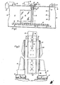
- FIG. 10 A portion of a sputter coating system 10 embodying the present invention is illustrated schematically by Figure'1 of the drawings.
- the system 10 includes an evacuable enclosure 12 containing a conveyor system 14 for moving substrates 16 to be coated along parallel spaced paths through the enclosure 12, a source 18 of inert, ionizable gas constructed-to introduce small quantities of the gas into the enclosure 12 and a magnetically enhanced cathode 20.
- the system 10 is a relatively large scale coating operation with the substrates 16, in the preferred embodiment of the invention, formed by sheets of architectural glass measuring 4-6 feet on a side.
- the cathode 20 is disposed between the substrate travel paths and is effective to establish a continuous band of plasma about it to produce sputtering from opposite faces of the cathode onto the substrates 16 passing the cathode.
- the enclosure 12 is illustrated schematically and in part as a pressure vessel having a generally cylindrical structurally strong wall 30 with a pumping duct 32 opening into it through which the enclosure is evacuated by a vacuum pump system schematically indicated by the reference character 34.
- the system 34 is schematically illustrated and preferably includes multiple pumps of different suitable types to enable quick and efficient pumping of the enclosure down to its operating pressure of from 1-3 microns.
- the enclosure 12 is equipped with one or more sealed bulkhead doors, not shown, to enable loading and unloading of substrates.
- the cathode 20 is illustrated as suspended from the uppermost section of the wall 30 via a sealed hatch-like cover 36 which is removable to enable cathode replacement.
- the conveyor system 14 is schematically illustrated in Figures 1 and 2 as formed by two identical conveyors effective to move substrates 16 along generally parallel paths through the enclosure 12.
- Each conveyor includes a supporting base 40 attached to the wall 30 and extending along and within the enclosure 12 and rollers 42 supported by the base by which substrates are moved through the enclosure.
- the rollers 42 are preferably "active" , or driven rollers connected by a suitable drive transmission to a driving motor.
- the transmission and driving motor may be of any suitable construction and are not illustrated by the drawings.
- substrate support frames 44 which are schematically illustrated as resting upon the rollers 4 2 and supporting the substrates on edge for movement along the respective paths.
- the supporting frames 44 are removable from the respective conveyors to enable loading and unloading of substrates outside the enclosure 12.
- the gas source 18 is effective to direct an inert ionizable gas, such as Argon, into the enclosure between the substrate paths of travel and generally towards the cathode 20.
- the gas source 18 is illustrated as including a storage tank 50 for liquefied or compressed Argon and a conduit 52 leading from the tank 50 through the wall 30 to a series of vertically spaced nozzles 54 located beyond the cathode 20 from the pumping duct 32.
- the mean free path of the gas molecules admitted into the enclosure is extremely long and it is important therefore to locate the nozzles 54 in line with the cathode 20 rather-than on one side or the other of the substrate paths of travel. Otherwise the substrates themselves would form "seals" and prevent the Argon molecules from reaching the vicinity of the cathode.
- the cathode 20 coacts with the gas to establish a plasma band, or belt, extending continuously about the electrode having first and second plasma belt sections extending along respective substrate faces and return sections extending transversely to the substrate travel direction.
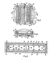
- the plasma belt location is illustrated by broken lines in Figures 3 and 4. Positive ions from the first and second plasma belt sections are accelerated into the cathode causing sputtering from the cathode to the adjacent substrate.
- the illustrated electrode mounting system 55 includes a mounting bracket which depends from the hatchway cover 36 and is attached to a cathode bracket by suitable detachable fasteners.
- the mounting brackets serve both to detachably connect the.cathode to the cover 36 for mounting the cathode and to electrically connect the cathode to the power supply 56.
- the mounting brackets can be of any suitable constructional size and shape, are preferably formed by a structurally strong electrically conductive nonmagnetic material, e.g. aluminum or copper, and are illustrated schematically.
- the mounting brackets are electrically insulated from the enclosure wall 30 which itself is electrically grounded to form the system anode.
- the power supply 56 can be of any suitable construction capable of providing at least 40 amps,D.C. at 600 volts.
- the negative power supply terminal is connected to the cathode while the positive terminal is grounded like the enclosure 12.
- the support structure 60 is constructed to enable easy replacement of the target.62,assure electrical continuity with the power supply 56 while avoiding interference with the fileds produced by the magnetic system 63, and to maintain the cathode at desirable operating temperature levels.
- the structure 60 includes a central core 70, a target support , or carrier 72 connected to the core 70 and a coolant system 74.
- the illustrated core 70 is formed by a nonmagnetic ellectrically conductive base member 76 and spacer bars 80.
- the member 76 is formed by a tubular aluminum extrusion or casting.
- the spacer bars extend longitudinally along the base member 76 and are spaced apart on opposite faces of the base member to define a slot-like longitudinal space on each of the base member faces.
- the spacer bars 80 are formed from the same kind of material as the core and are attached to the base member 76 by screws 82.
- the opposed lateral sides of the base member 76 define a series of openings which, in part, communicate the interior of the base member with the inside of the enclosure 12 so that the interior of the base member is evacuated when the enclosure is pumped down.
- the target support, or carrier, 72 assures electrical continuity between the target and the power supply and transfers heat from the target.
- the target carrier is mounted on the support structure 60 and formed of a nonmagnetic material which has a high heat and electrical conductivity (preferably copper).
- the carrier is shaped to define an elongated rectangular band detachably connected to the support structure 60 by screws 86 threaded into the spacer bars 80.
- the target carrier can be formed by individual planar rectangular copper members each assembled to the core or by a single unit of brazed, or otherwise bonded, copper plate components. However formed, all parts of the target carrier have electrical continuity with the remainder of the support structure 60 and each other part of the target carrier itself.
- the target carrier defines bight portions 72a which extend across the opposite ends of the cathode.
- the illustrated base member and spacer bars do not extend across the ends of the support structure 60 but the bight portions 72a are rigidly attached to the remainder of the target support and do not require additional support.
- the preferred coolant system 74 is formed by a copper coolant conduit 90 helically coiled about the inside of the target carrier in the slot-like space between the bars 80.
- the conduit '90 is soft soldered to the interior of the target support to assure maximum heat conduction from the target support to the coolant. Intake and discharge ends of the conduit 90 ' extend through the wall 30 via the cover 36 (See Figure 1) to a coolant source which can be a commonly available source of tapwater.
- the coolant conduit sections leading away from the outside of the enclosure are formed from plastic or other suitable electrical insulating material.
- the preferred sputtering target 62 extends about the cathode and conforms to the shape of the target carrier, i.e. the target has a rectangular band or belt-like configuration.
- the sputtering target is mounted in electrical continuity with the carrier 72 and core 70 so that the target is at the voltage level of the negative power supply terminal.
- the sputtering target includes first and second target face portions 92, 94, which face oppositely from the cathode toward a respective adjacent one of the substrate travel paths and bridging portions 96 extending between adjacent ends of the target face portions.
- the bridging target portions are fashioned from planar rectangular plates of nonmagnetic stainless steel or some other inexpensive easily formed nonmagnetic material while the first and second target face portions are formed from rectangular elongated plates of sputter coating material.
- the lengths of the first and second target face portions are such that the target face portions each extend at least 5 cm. beyond the upper and lower edges of the substrate being coated to assure substantially uniform coating of the marginal portions of the substrate (the distance between the planes of the substrate and target face portion being around 5 cm).
- sputtering does occur from the faces of the bridging portions 96, none of the material sputtered from these portions strikes the substrates. Sputtering occurs along a line-of-sight from the sputtering surface and since the planes of the bridging target portions are beyond the upper and lower edges of the substrates the material from the bridging target portions is not deposited on the substrates. Hence the sputter coating wich occurs is limited to the material forming the first and second target face portions. Erosion of the bridging portions 96 occurs but these portions are made from m a-terials which are inexpensively fabricated and usually of relatively low intrinsic value, at least compared to the value of the material forming the first and second target face portions.
- the system 68 includes a magnetic field producing structure 100 and field directing members 102, 104 which coact to establish and direct a magnetic field for. maintaining the plasma close to and distributed substantially uniformly across the width of the target face portions.
- the field directing members 102, 104 are formed by a paramagnetic material , such as magnetic stainless steel.
- Each field directing member includes a plate 106 shaped substantially to conform to the silhouette of the cathode and overlying one lateral side of the cathode, and a target clamping element 108 detachably connected to the periphery of the associated plate l06 by screws 110 ( Figure 3).
- the clamping element 108 is, in the illustrated embodiment, a rectangular shaped framework which fits snugly about the periphery of the plate 106 and extends along one lateral side of the target face portions 92, 94 and the bridging portions 96. When the screws 110 are tightened the clamping elements engage the face portions to both secure the target plates in place on the electrode and establish electrical contact between the target and the target carrier.
- the plates 106 and target clamping elements 108 coact to provide for positive mounting of target plates of virtually any desired material to the cathode without the necessity for machining the target plates by drilling holes, ect. which might otherwise be required for mounting.
- clamping elements and plates are magnetic conductors and as such direct the magnetic field over and across the target face portions 92, 94 as illustrated by broken lines in Figures 3 and 4. This effectively distributes the plasma evenly across the target plates so that sputtering occurs uniformly from the exposed target face portions and the life of the target is maximized.
- Figure 4 of the drawings illustrates the target erosion pattern in cross-section. The only portions of the target which are not consumed are the narrow marginal sections which are clamped by the elements 108 and these can be quite small.
- the plates l06 are detachably clamped to the support structure 60 by bolt and nut fasteners 112.
- the bolts extend through clearance holes 11 4 in the plates 106 and aligned openings in the core 70. Additional vent openings may be formed in the plates 106 which communicate directly with holes in the core 70 to assure that the central space of the core 70 is evacuated along with the rest of the enclosure 12.
- the magnetic field producing structure 100 both produces the plasma confining magnetic field and causes circulation of the plasma about the cathode.
- the structure 100 is preferably formed by a plurality of permanent bar-type magnets having their opposite ends supported respectively by the plates 106.
- the magnetic poles are aligned so that the north pole of each magnet is supported by one plate 106 and the respective south poles are supported by the other plate.
- the magnets are spaced apart about the cathode in.a belt-shaped array within the perimeter of the target and just inside the target carrier inner periphery. The spaced magnets are effective to induce movement of the electrons in the plasma around the cathode through the plasma region.
- the new cathode construction enables substantial flexibility of usage. For example, if desirable, side by side target plates of dissimilar sputtering materials can be clamped in place on the target carrier so that multiple sputtering materials can be placed on each of two substrates simultaneously from a single electrode.
- the new cathode can also be "compounded" simply by constructing a series of two or more cathodes connected in common to a power supply and coolant source with adjacent cathodes sharing the intervening magnetic field directing plate 106. This construction .enables the use of multiple target materials or increased sputtering rates of one target material applied to each of the compounded cathodes.
Landscapes
- Chemical & Material Sciences (AREA)
- Engineering & Computer Science (AREA)
- Physics & Mathematics (AREA)
- Plasma & Fusion (AREA)
- Analytical Chemistry (AREA)
- Materials Engineering (AREA)
- Mechanical Engineering (AREA)
- Metallurgy (AREA)
- Organic Chemistry (AREA)
- Chemical Kinetics & Catalysis (AREA)
- Physical Vapour Deposition (AREA)
- Surface Treatment Of Glass (AREA)
- Battery Electrode And Active Subsutance (AREA)
- Physical Deposition Of Substances That Are Components Of Semiconductor Devices (AREA)
- Saccharide Compounds (AREA)
- Organic Low-Molecular-Weight Compounds And Preparation Thereof (AREA)
- Coating By Spraying Or Casting (AREA)
- Fodder In General (AREA)
- Pharmaceuticals Containing Other Organic And Inorganic Compounds (AREA)
- Compounds Of Alkaline-Earth Elements, Aluminum Or Rare-Earth Metals (AREA)
- Medicines That Contain Protein Lipid Enzymes And Other Medicines (AREA)
- Chemically Coating (AREA)
- Application Of Or Painting With Fluid Materials (AREA)
Priority Applications (1)
| Application Number | Priority Date | Filing Date | Title |
|---|---|---|---|
| AT79870031T ATE3228T1 (de) | 1978-12-20 | 1979-12-19 | Zerstaeubungskathode und vorrichtung zum beschichten grossflaechiger substrate durch kathodenzerstaeubung. |
Applications Claiming Priority (2)
| Application Number | Priority Date | Filing Date | Title |
|---|---|---|---|
| US05/971,196 US4194962A (en) | 1978-12-20 | 1978-12-20 | Cathode for sputtering |
| US971196 | 1978-12-20 |
Publications (2)
| Publication Number | Publication Date |
|---|---|
| EP0014819A1 true EP0014819A1 (fr) | 1980-09-03 |
| EP0014819B1 EP0014819B1 (fr) | 1983-05-04 |
Family
ID=25518049
Family Applications (1)
| Application Number | Title | Priority Date | Filing Date |
|---|---|---|---|
| EP79870031A Expired EP0014819B1 (fr) | 1978-12-20 | 1979-12-19 | Cathode pour pulvérisation et appareil pour revêtir par pulvérisation cathodique des substrats de grande surface |
Country Status (12)
| Country | Link |
|---|---|
| US (1) | US4194962A (fr) |
| EP (1) | EP0014819B1 (fr) |
| JP (1) | JPS5585673A (fr) |
| AT (1) | ATE3228T1 (fr) |
| BR (1) | BR7908323A (fr) |
| CA (1) | CA1133424A (fr) |
| DE (1) | DE2965330D1 (fr) |
| DK (1) | DK157563C (fr) |
| ES (1) | ES487573A0 (fr) |
| FI (1) | FI63600C (fr) |
| IE (1) | IE49129B1 (fr) |
| NO (1) | NO152979C (fr) |
Cited By (5)
| Publication number | Priority date | Publication date | Assignee | Title |
|---|---|---|---|---|
| EP0105407A3 (en) * | 1982-09-30 | 1984-10-03 | Gte Products Corporation | A sputtering cathode apparatus |
| GB2152953A (en) * | 1984-01-19 | 1985-08-14 | Univ British Columbia | Planar magnetron sputtering device |
| EP0065277B1 (fr) * | 1981-05-20 | 1986-01-08 | Kabushiki Kaisha Toshiba | Procédé de gravure à sec à grande vitesse |
| EP0115119A3 (en) * | 1983-01-26 | 1986-04-16 | Materials Research Corporation | Shaped field magnetron electrode |
| FR2596920A1 (fr) * | 1986-04-03 | 1987-10-09 | Saint Roch Sa Glaceries | Cathode de pulverisation |
Families Citing this family (31)
| Publication number | Priority date | Publication date | Assignee | Title |
|---|---|---|---|---|
| US4265729A (en) * | 1978-09-27 | 1981-05-05 | Vac-Tec Systems, Inc. | Magnetically enhanced sputtering device |
| US4309261A (en) * | 1980-07-03 | 1982-01-05 | University Of Sydney | Method of and apparatus for reactively sputtering a graded surface coating onto a substrate |
| US4290877A (en) * | 1980-09-08 | 1981-09-22 | The United States Of America As Represented By The Secretary Of The Interior | Sputtering apparatus for coating elongated tubes and strips |
| US4361472A (en) * | 1980-09-15 | 1982-11-30 | Vac-Tec Systems, Inc. | Sputtering method and apparatus utilizing improved ion source |
| US4422896A (en) * | 1982-01-26 | 1983-12-27 | Materials Research Corporation | Magnetically enhanced plasma process and apparatus |
| US4525262A (en) * | 1982-01-26 | 1985-06-25 | Materials Research Corporation | Magnetron reactive bias sputtering method and apparatus |
| US4415427A (en) * | 1982-09-30 | 1983-11-15 | Gte Products Corporation | Thin film deposition by sputtering |
| US4597847A (en) * | 1984-10-09 | 1986-07-01 | Iodep, Inc. | Non-magnetic sputtering target |
| US5215639A (en) * | 1984-10-09 | 1993-06-01 | Genus, Inc. | Composite sputtering target structures and process for producing such structures |
| US4828668A (en) * | 1986-03-10 | 1989-05-09 | Semiconductor Energy Laboratory Co., Ltd. | Sputtering system for deposition on parallel substrates |
| US4812217A (en) * | 1987-04-27 | 1989-03-14 | American Telephone And Telegraph Company, At&T Bell Laboratories | Method and apparatus for feeding and coating articles in a controlled atmosphere |
| JPH0351971Y2 (fr) * | 1988-05-12 | 1991-11-08 | ||
| US4915805A (en) * | 1988-11-21 | 1990-04-10 | At&T Bell Laboratories | Hollow cathode type magnetron apparatus construction |
| DE3938267C2 (de) * | 1989-11-17 | 1997-03-27 | Leybold Ag | Vorrichtung zum Heizen von Substraten |
| DE4135939A1 (de) * | 1991-10-31 | 1993-05-06 | Leybold Ag, 6450 Hanau, De | Zerstaeubungskathode |
| US5322606A (en) * | 1991-12-26 | 1994-06-21 | Xerox Corporation | Use of rotary solenoid as a shutter actuator on a rotating arm |
| KR100327716B1 (ko) * | 1994-01-11 | 2002-06-27 | 노만 에이취. 폰드 | 진공처리시스템및진공처리시스템내에서의기판조작방법 |
| JPH07316810A (ja) * | 1994-05-27 | 1995-12-05 | Fuji Xerox Co Ltd | スパッタリング装置 |
| DE4428136A1 (de) * | 1994-08-09 | 1996-02-15 | Leybold Ag | Vakuum-Beschichtungsanlage |
| IL127236A0 (en) * | 1997-11-26 | 1999-09-22 | Vapor Technologies Inc | Apparatus for sputtering or arc evaporation |
| US5997705A (en) * | 1999-04-14 | 1999-12-07 | Vapor Technologies, Inc. | Rectangular filtered arc plasma source |
| US6309516B1 (en) | 1999-05-07 | 2001-10-30 | Seagate Technology Llc | Method and apparatus for metal allot sputtering |
| US7678198B2 (en) * | 2004-08-12 | 2010-03-16 | Cardinal Cg Company | Vertical-offset coater |
| WO2006028774A2 (fr) * | 2004-09-03 | 2006-03-16 | Cardinal Cg Company | Machine a enduire a systeme de transport a deux boucles separees |
| US7498587B2 (en) * | 2006-05-01 | 2009-03-03 | Vapor Technologies, Inc. | Bi-directional filtered arc plasma source |
| WO2008114718A1 (fr) * | 2007-03-16 | 2008-09-25 | National University Corporation Tohoku University | Appareil de pulvérisation magnétron |
| KR101166396B1 (ko) * | 2007-03-30 | 2012-07-23 | 도쿄엘렉트론가부시키가이샤 | 회전 마그넷 스퍼터 장치 |
| DE102007052524B4 (de) * | 2007-11-01 | 2012-05-31 | Von Ardenne Anlagentechnik Gmbh | Transportmittel und Vakuumbeschichtungsanlage für Substrate unterschiedlicher Größe |
| US8842357B2 (en) | 2008-12-31 | 2014-09-23 | View, Inc. | Electrochromic device and method for making electrochromic device |
| US9664974B2 (en) | 2009-03-31 | 2017-05-30 | View, Inc. | Fabrication of low defectivity electrochromic devices |
| US9966242B2 (en) * | 2014-09-29 | 2018-05-08 | Xinsheng Guo | High throughput vacuum deposition sources and system |
Citations (5)
| Publication number | Priority date | Publication date | Assignee | Title |
|---|---|---|---|---|
| US3414503A (en) * | 1964-03-12 | 1968-12-03 | Glaverbel | Apparatus for coating the surface of plates uniformly by cathode sputtering |
| FR2148245A1 (fr) * | 1971-08-04 | 1973-03-11 | Elektromat Veb | |
| US3956093A (en) * | 1974-12-16 | 1976-05-11 | Airco, Inc. | Planar magnetron sputtering method and apparatus |
| DE2655942A1 (de) * | 1976-12-10 | 1978-06-15 | Tokuda Seisakusho Kawasaki Kk | Zerstaeubungsvorrichtung |
| US4116806A (en) * | 1977-12-08 | 1978-09-26 | Battelle Development Corporation | Two-sided planar magnetron sputtering apparatus |
Family Cites Families (5)
| Publication number | Priority date | Publication date | Assignee | Title |
|---|---|---|---|---|
| FR2132033B1 (fr) * | 1971-04-02 | 1975-10-24 | Delog Detag Flachglas Ag | |
| US4041353A (en) * | 1971-09-07 | 1977-08-09 | Telic Corporation | Glow discharge method and apparatus |
| US3878085A (en) * | 1973-07-05 | 1975-04-15 | Sloan Technology Corp | Cathode sputtering apparatus |
| US4013532A (en) * | 1975-03-03 | 1977-03-22 | Airco, Inc. | Method for coating a substrate |
| US4126530A (en) * | 1977-08-04 | 1978-11-21 | Telic Corporation | Method and apparatus for sputter cleaning and bias sputtering |
-
1978
- 1978-12-20 US US05/971,196 patent/US4194962A/en not_active Expired - Lifetime
-
1979
- 1979-11-30 JP JP15450179A patent/JPS5585673A/ja active Pending
- 1979-12-18 IE IE2464/79A patent/IE49129B1/en not_active IP Right Cessation
- 1979-12-19 EP EP79870031A patent/EP0014819B1/fr not_active Expired
- 1979-12-19 CA CA342,241A patent/CA1133424A/fr not_active Expired
- 1979-12-19 DK DK543679A patent/DK157563C/da not_active IP Right Cessation
- 1979-12-19 BR BR7908323A patent/BR7908323A/pt unknown
- 1979-12-19 DE DE7979870031T patent/DE2965330D1/de not_active Expired
- 1979-12-19 NO NO794182A patent/NO152979C/no unknown
- 1979-12-19 FI FI793982A patent/FI63600C/fi not_active IP Right Cessation
- 1979-12-19 AT AT79870031T patent/ATE3228T1/de not_active IP Right Cessation
- 1979-12-20 ES ES487573A patent/ES487573A0/es active Granted
Patent Citations (5)
| Publication number | Priority date | Publication date | Assignee | Title |
|---|---|---|---|---|
| US3414503A (en) * | 1964-03-12 | 1968-12-03 | Glaverbel | Apparatus for coating the surface of plates uniformly by cathode sputtering |
| FR2148245A1 (fr) * | 1971-08-04 | 1973-03-11 | Elektromat Veb | |
| US3956093A (en) * | 1974-12-16 | 1976-05-11 | Airco, Inc. | Planar magnetron sputtering method and apparatus |
| DE2655942A1 (de) * | 1976-12-10 | 1978-06-15 | Tokuda Seisakusho Kawasaki Kk | Zerstaeubungsvorrichtung |
| US4116806A (en) * | 1977-12-08 | 1978-09-26 | Battelle Development Corporation | Two-sided planar magnetron sputtering apparatus |
Cited By (7)
| Publication number | Priority date | Publication date | Assignee | Title |
|---|---|---|---|---|
| EP0065277B1 (fr) * | 1981-05-20 | 1986-01-08 | Kabushiki Kaisha Toshiba | Procédé de gravure à sec à grande vitesse |
| EP0105407A3 (en) * | 1982-09-30 | 1984-10-03 | Gte Products Corporation | A sputtering cathode apparatus |
| EP0115119A3 (en) * | 1983-01-26 | 1986-04-16 | Materials Research Corporation | Shaped field magnetron electrode |
| GB2152953A (en) * | 1984-01-19 | 1985-08-14 | Univ British Columbia | Planar magnetron sputtering device |
| FR2596920A1 (fr) * | 1986-04-03 | 1987-10-09 | Saint Roch Sa Glaceries | Cathode de pulverisation |
| EP0241447A1 (fr) * | 1986-04-03 | 1987-10-14 | S.A. Glaceries de Saint-Roch | Cathode de pulvérisation |
| US4780190A (en) * | 1986-04-03 | 1988-10-25 | Glaceries De Saint-Roch | Sputtering cathode |
Also Published As
| Publication number | Publication date |
|---|---|
| ES8101129A1 (es) | 1980-12-16 |
| ES487573A0 (es) | 1980-12-16 |
| NO152979C (no) | 1985-12-27 |
| ATE3228T1 (de) | 1983-05-15 |
| BR7908323A (pt) | 1980-09-16 |
| FI793982A7 (fi) | 1980-06-21 |
| FI63600B (fi) | 1983-03-31 |
| NO794182L (no) | 1980-06-23 |
| DK157563C (da) | 1990-06-18 |
| EP0014819B1 (fr) | 1983-05-04 |
| DK157563B (da) | 1990-01-22 |
| US4194962A (en) | 1980-03-25 |
| DE2965330D1 (en) | 1983-06-09 |
| CA1133424A (fr) | 1982-10-12 |
| JPS5585673A (en) | 1980-06-27 |
| IE792464L (en) | 1980-06-20 |
| FI63600C (fi) | 1983-07-11 |
| IE49129B1 (en) | 1985-08-07 |
| NO152979B (no) | 1985-09-16 |
| DK543679A (da) | 1980-06-21 |
Similar Documents
| Publication | Publication Date | Title |
|---|---|---|
| EP0014819B1 (fr) | Cathode pour pulvérisation et appareil pour revêtir par pulvérisation cathodique des substrats de grande surface | |
| US5196105A (en) | System for coating substrates with magnetron cathodes | |
| EP0051635B1 (fr) | Cible à pulvérisation et appareil à décharge luminescente pour effectuer un revêtement | |
| US3956093A (en) | Planar magnetron sputtering method and apparatus | |
| US4946576A (en) | Apparatus for the application of thin layers to a substrate | |
| KR100659828B1 (ko) | 이온화 물리적 증착 방법 및 장치 | |
| CA1206914A (fr) | Appareil de pulverisation cathodique | |
| US4915805A (en) | Hollow cathode type magnetron apparatus construction | |
| US20020153103A1 (en) | Plasma treatment apparatus | |
| KR20010024668A (ko) | 마그네트론 스퍼터링 소스 | |
| JPH0627323B2 (ja) | スパツタリング方法及びその装置 | |
| US4798663A (en) | Sputtering installation for the reactive coating of a substrate with hard materials | |
| US4810347A (en) | Penning type cathode for sputter coating | |
| EP0081331B1 (fr) | Appareil pour pulvérisation sous vide | |
| EP1193729A2 (fr) | Procédé et appareil de pulvérisation magnétron | |
| US3616402A (en) | Sputtering method and apparatus | |
| US4175029A (en) | Apparatus for ion plasma coating of articles | |
| US4673480A (en) | Magnetically enhanced sputter source | |
| WO1992007970A1 (fr) | Procede de revetement par pulverisation par magnetron et appareil avec cathode a aimant rotatif | |
| EP0162643B1 (fr) | Source pour revêtement par pulvérisation ayant plusieurs cibles annulaires | |
| EP0715336A2 (fr) | Méthode et dispositif de pulvérisation par magnétron planaire | |
| US4780190A (en) | Sputtering cathode | |
| JP2555004B2 (ja) | スパッタリング装置 | |
| JP2001348663A (ja) | スパッタリング装置 | |
| JP2001335930A (ja) | 薄膜形成装置 |
Legal Events
| Date | Code | Title | Description |
|---|---|---|---|
| PUAI | Public reference made under article 153(3) epc to a published international application that has entered the european phase |
Free format text: ORIGINAL CODE: 0009012 |
|
| AK | Designated contracting states |
Designated state(s): AT BE CH DE FR GB IT LU NL SE |
|
| 17P | Request for examination filed |
Effective date: 19801020 |
|
| ITCL | It: translation for ep claims filed |
Representative=s name: ING. C. GREGORJ S.P.A. |
|
| TCAT | At: translation of patent claims filed | ||
| DET | De: translation of patent claims | ||
| ITF | It: translation for a ep patent filed | ||
| GRAA | (expected) grant |
Free format text: ORIGINAL CODE: 0009210 |
|
| AK | Designated contracting states |
Designated state(s): AT BE CH DE FR GB IT LU NL SE |
|
| REF | Corresponds to: |
Ref document number: 3228 Country of ref document: AT Date of ref document: 19830515 Kind code of ref document: T |
|
| ET | Fr: translation filed | ||
| REF | Corresponds to: |
Ref document number: 2965330 Country of ref document: DE Date of ref document: 19830609 |
|
| PLBE | No opposition filed within time limit |
Free format text: ORIGINAL CODE: 0009261 |
|
| STAA | Information on the status of an ep patent application or granted ep patent |
Free format text: STATUS: NO OPPOSITION FILED WITHIN TIME LIMIT |
|
| 26N | No opposition filed | ||
| ITTA | It: last paid annual fee | ||
| REG | Reference to a national code |
Ref country code: CH Ref legal event code: PUE Owner name: GLACERIES DE SAINT-ROCH, S.A. |
|
| REG | Reference to a national code |
Ref country code: GB Ref legal event code: 732E |
|
| REG | Reference to a national code |
Ref country code: FR Ref legal event code: TP |
|
| NLS | Nl: assignments of ep-patents |
Owner name: S.A. GLACERIES DE SAINT-ROCH TE SAMBREVILLE, BELGI |
|
| EPTA | Lu: last paid annual fee | ||
| PGFP | Annual fee paid to national office [announced via postgrant information from national office to epo] |
Ref country code: FR Payment date: 19941025 Year of fee payment: 16 |
|
| PGFP | Annual fee paid to national office [announced via postgrant information from national office to epo] |
Ref country code: BE Payment date: 19941031 Year of fee payment: 16 |
|
| PGFP | Annual fee paid to national office [announced via postgrant information from national office to epo] |
Ref country code: SE Payment date: 19941107 Year of fee payment: 16 |
|
| PGFP | Annual fee paid to national office [announced via postgrant information from national office to epo] |
Ref country code: GB Payment date: 19941111 Year of fee payment: 16 |
|
| PGFP | Annual fee paid to national office [announced via postgrant information from national office to epo] |
Ref country code: LU Payment date: 19941201 Year of fee payment: 16 |
|
| PGFP | Annual fee paid to national office [announced via postgrant information from national office to epo] |
Ref country code: AT Payment date: 19941212 Year of fee payment: 16 |
|
| PGFP | Annual fee paid to national office [announced via postgrant information from national office to epo] |
Ref country code: CH Payment date: 19941230 Year of fee payment: 16 |
|
| PGFP | Annual fee paid to national office [announced via postgrant information from national office to epo] |
Ref country code: NL Payment date: 19941231 Year of fee payment: 16 |
|
| PGFP | Annual fee paid to national office [announced via postgrant information from national office to epo] |
Ref country code: DE Payment date: 19950124 Year of fee payment: 16 |
|
| EAL | Se: european patent in force in sweden |
Ref document number: 79870031.6 |
|
| PG25 | Lapsed in a contracting state [announced via postgrant information from national office to epo] |
Ref country code: LU Free format text: LAPSE BECAUSE OF NON-PAYMENT OF DUE FEES Effective date: 19951219 Ref country code: GB Effective date: 19951219 Ref country code: AT Effective date: 19951219 |
|
| PG25 | Lapsed in a contracting state [announced via postgrant information from national office to epo] |
Ref country code: SE Effective date: 19951220 |
|
| PG25 | Lapsed in a contracting state [announced via postgrant information from national office to epo] |
Ref country code: CH Effective date: 19951231 Ref country code: BE Effective date: 19951231 |
|
| BERE | Be: lapsed |
Owner name: S.A GLACERIES DE SAINT-ROCH Effective date: 19951231 |
|
| PG25 | Lapsed in a contracting state [announced via postgrant information from national office to epo] |
Ref country code: NL Effective date: 19960701 |
|
| GBPC | Gb: european patent ceased through non-payment of renewal fee |
Effective date: 19951219 |
|
| REG | Reference to a national code |
Ref country code: CH Ref legal event code: PL |
|
| PG25 | Lapsed in a contracting state [announced via postgrant information from national office to epo] |
Ref country code: FR Effective date: 19960830 |
|
| NLV4 | Nl: lapsed or anulled due to non-payment of the annual fee |
Effective date: 19960701 |
|
| PG25 | Lapsed in a contracting state [announced via postgrant information from national office to epo] |
Ref country code: DE Effective date: 19960903 |
|
| REG | Reference to a national code |
Ref country code: FR Ref legal event code: ST |