EP0014916A1 - Einrichtung zur Druckentlastung von Räumen mittels Klappen - Google Patents
Einrichtung zur Druckentlastung von Räumen mittels Klappen Download PDFInfo
- Publication number
- EP0014916A1 EP0014916A1 EP80100645A EP80100645A EP0014916A1 EP 0014916 A1 EP0014916 A1 EP 0014916A1 EP 80100645 A EP80100645 A EP 80100645A EP 80100645 A EP80100645 A EP 80100645A EP 0014916 A1 EP0014916 A1 EP 0014916A1
- Authority
- EP
- European Patent Office
- Prior art keywords
- flaps
- pressure
- pressure relief
- rotation
- axes
- Prior art date
- Legal status (The legal status is an assumption and is not a legal conclusion. Google has not performed a legal analysis and makes no representation as to the accuracy of the status listed.)
- Granted
Links
- 239000000853 adhesive Substances 0.000 description 1
- 230000001070 adhesive effect Effects 0.000 description 1
- 239000000945 filler Substances 0.000 description 1
Images
Classifications
-
- E—FIXED CONSTRUCTIONS
- E06—DOORS, WINDOWS, SHUTTERS, OR ROLLER BLINDS IN GENERAL; LADDERS
- E06B—FIXED OR MOVABLE CLOSURES FOR OPENINGS IN BUILDINGS, VEHICLES, FENCES OR LIKE ENCLOSURES IN GENERAL, e.g. DOORS, WINDOWS, BLINDS, GATES
- E06B5/00—Doors, windows, or like closures for special purposes; Border constructions therefor
- E06B5/10—Doors, windows, or like closures for special purposes; Border constructions therefor for protection against air-raid or other war-like action; for other protective purposes
- E06B5/12—Doors, windows, or like closures for special purposes; Border constructions therefor for protection against air-raid or other war-like action; for other protective purposes against air pressure, explosion, or gas
- E06B5/125—Closures for relieving excess pressure inside the building
-
- E—FIXED CONSTRUCTIONS
- E06—DOORS, WINDOWS, SHUTTERS, OR ROLLER BLINDS IN GENERAL; LADDERS
- E06B—FIXED OR MOVABLE CLOSURES FOR OPENINGS IN BUILDINGS, VEHICLES, FENCES OR LIKE ENCLOSURES IN GENERAL, e.g. DOORS, WINDOWS, BLINDS, GATES
- E06B5/00—Doors, windows, or like closures for special purposes; Border constructions therefor
- E06B5/10—Doors, windows, or like closures for special purposes; Border constructions therefor for protection against air-raid or other war-like action; for other protective purposes
- E06B5/12—Doors, windows, or like closures for special purposes; Border constructions therefor for protection against air-raid or other war-like action; for other protective purposes against air pressure, explosion, or gas
-
- G—PHYSICS
- G21—NUCLEAR PHYSICS; NUCLEAR ENGINEERING
- G21C—NUCLEAR REACTORS
- G21C9/00—Emergency protection arrangements structurally associated with the reactor, e.g. safety valves provided with pressure equalisation devices
- G21C9/004—Pressure suppression
-
- Y—GENERAL TAGGING OF NEW TECHNOLOGICAL DEVELOPMENTS; GENERAL TAGGING OF CROSS-SECTIONAL TECHNOLOGIES SPANNING OVER SEVERAL SECTIONS OF THE IPC; TECHNICAL SUBJECTS COVERED BY FORMER USPC CROSS-REFERENCE ART COLLECTIONS [XRACs] AND DIGESTS
- Y02—TECHNOLOGIES OR APPLICATIONS FOR MITIGATION OR ADAPTATION AGAINST CLIMATE CHANGE
- Y02E—REDUCTION OF GREENHOUSE GAS [GHG] EMISSIONS, RELATED TO ENERGY GENERATION, TRANSMISSION OR DISTRIBUTION
- Y02E30/00—Energy generation of nuclear origin
- Y02E30/30—Nuclear fission reactors
Definitions
- the invention relates to a device for relieving pressure in rooms by means of flaps which are connected to the walls or ceilings of these rooms via swivel joints and release relief openings when a predetermined pressure is exceeded.
- the flaps should remain in the open position after pressure equalization.
- the flaps are designed as rotary wings, the axes of rotation of which run asymmetrically and are inclined in the direction of detenting.
- the flaps After the flaps have been pressurized, they open with their larger surface in the direction of pressure relief and release the relief cross-section. Due to the inclination of the axes of rotation, the flaps remain in the open position after the pressure compensation has been set.
- the axes of rotation are arranged such that the force from the area difference multiplied by the desired opening pressure is greater than the S of the holding forces. This measure ensures that the device responds at the specified opening pressure.
- FIGS. 1 to 3 The device according to the invention is described using an exemplary embodiment and the schematic drawings of FIGS. 1 to 3.
- a room 1 the walls 2 and ceilings 3 of which are made of concrete, has a relief opening 4 which is closed by two flaps 7.
- the axes of rotation 9 of which are inclined in the pressure relief direction 10.
- the axes of rotation 9 run parallel to the edges 12 of a flap, so that the flaps in their open position have the same inclination as the rotation Axes 9:
- the axes of rotation are arranged asymmetrically to the flaps 7 and divide the total area of a flap into two rectangular surfaces 13, 14 of different sizes.
- the axes of rotation are arranged so that the force from the area difference multiplied by the specified opening pressure is greater than the sum of the holding forces, such as frictional forces in the pivot bearings and adhesive forces of the seal.
- the flaps 7 with their larger surface 12 open in the pressure relief direction 10 and open the relief opening 4. Due to the inclination of the axes of rotation 11, the flaps remain in the open position after division of a pressure equalization.
- the device according to the invention can also be operated with only one flap 7 or with more than two flaps.
- the asymmetrical and inclined arrangement of the axes of rotation 11 is always essential.
- the proposed device creates a simple pressure relief which prevents damage to parts of the building or flaps.
Landscapes
- Engineering & Computer Science (AREA)
- Structural Engineering (AREA)
- Physics & Mathematics (AREA)
- Civil Engineering (AREA)
- Plasma & Fusion (AREA)
- General Engineering & Computer Science (AREA)
- High Energy & Nuclear Physics (AREA)
- Architecture (AREA)
- Building Environments (AREA)
- Control Of Fluid Pressure (AREA)
Abstract
Description
- Die Erfindung betrifft eine Einrichtung zur Druckentlastung von Räumen mittels Klappen die über Drehgelenke mit den Wänden oder Decken dieser Räume verbunden sind und bei Überschreiten eines vorgegebenen Druckes Entlastungsöffnungen freigeben.
- Eine derartige Einrichtung ist aus der DE-OS 26 53 694 bekannt. Die darin beschriebene Ausbildung hat den Nachteil, daß die Klappen beim Aufeinandertreffen beschädigt werden. Außerdem besteht die Gefahr, daß die Klappen nach erfolgtem Ausströmen wieder in ihre Schließstellung zurückfallen. Dieses frühzeitige Schließen ist bei verschiedenen Füllstoffen des entlasteten Raumes unerwünscht.
- Es ist die Aufgabe der Erfindung eine Einrichtung zur Druckentlastung von Räumen anzugeben bei deren Ansprechen eine Beschädigung von Gebäudeteilen durch die Klappen sowie der Klappen selbst ausgeschlossen ist. Außerdem sollen die Klappen nach erfolgtem Druckausgleich in Offenstellung bleiben.
- Gelöst wird die Aufgabe erfindungsgemäß dadurch, daß die Klappen als Drehflügel ausgebildet si d, deren Drehachsen asymetrisch verlaufen und in Druckent astungsrichtung geneigt sind.
- Nach einer Druckbeaufschlagung der Klappen öffnen dieselben mit ihrer größeren Fläche in Druckent astungsrichtung und geben den Entlastungsquerschnitt frei Bedingt durch die Neigung der Drehachsen verharren die lappen nach Einstellung des Druckausgleiches in geöf neter Stellung.
- Die Drehachsen sind dabei derart angeordnet, daß die Kraft aus der Flächendifferenz multipliziert mit dem gewünschten Öffnungsdruck größer ist als die S der Haltekräfte. Diese Maßnahme gewährleistet das Ansprechen der Einrichtung bei dem vorgegebenen Öffnungsdruck.
- An einem Ausführungsbeispiel und den schematischen Zeichnungen der Fig. 1 bis 3 wird die erfdindungsgemäße Einrichtung beschrieben.
- Es zeigen:
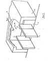
- Fig. 1 eine perspektivische Darstellung eines Raumes mit geöffneten Klappen,
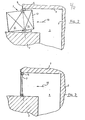
- Fig. 2 einen Schnitt entlang der Linie A-A der Fig. 1 mit geöffneten Klappen und
- Fig. 3 einen Schnitt entlang der Linie A-A der Fig. 1 mit geschlossenen Klappen.
- Ein Raum 1, dessen Wände 2 und Decken 3 aus Beton bestehen weist eine Entlastungsöffnung 4 auf die mit zwei Klappen 7 verschlossen ist.
- An den Wangen 6 und den Klappen 7 sind Anschläge 8 angebracht, deren Drehachsen 9 in Druckentlastungsrichtung 10 geneigt sind. Die Drehachsen 9 verlaufen dabei parallel zu den Kanten 12 einer Klappe, so daß die Klappen in ihrer Offenstellung die gleiche Neigung aufweisen wie die Drehachsen 9: Die Drehachsen sind asymetrisch zu den Klappen 7 angeordnet und unterteilen die Gesamtfläche einer Klappe in zwei verschieden große rechteckige Flächen 13,14. Die Anordnung der Drehachsen wird so vorgenommen, daß die Kraft aus der Flächendifferenz multipliziert mit dem vorgegebenen Öffnungsdruck größer ist als die Summe der Haltekräfte wie z.B. Reibungskräfte in den Drehlagern und Klebekräfte der Dichtung. Tritt in dem Raum 1 eine unzulässige Druckerhöhung auf, so öffnen die Klappen 7 mit ihrer größeren Fläche 12 in Druckentlastungsrichtung 10 und geben die Entlastungsöffnung 4 frei. Bedingt durch die Neigung der Drehachsen 11 verharren die Klappen nach Einteilung eines Druckausgleiches in geöffneter Stellung. Die erfindungsgemäße Einrichtung kann auch mit nur einer Klappe 7 oder mit mehr als zwei Klappen betrieben werden. Wesentlich ist immer das asymetrische und geneigte Anordnen der Drehachsen 11.
- Die vorgeschlagene Einrichtung schafft eine einfach aufgebaute Druckentlastung die eine Beschädigung an Gebäudeteilen bzw. Klappen ausschließt.
Claims (2)
Priority Applications (1)
| Application Number | Priority Date | Filing Date | Title |
|---|---|---|---|
| AT80100645T ATE2760T1 (de) | 1979-02-26 | 1980-02-08 | Einrichtung zur druckentlastung von raeumen mittels klappen. |
Applications Claiming Priority (2)
| Application Number | Priority Date | Filing Date | Title |
|---|---|---|---|
| DE2907430A DE2907430C2 (de) | 1979-02-26 | 1979-02-26 | Einrichtung zur Druckentlastung von Räumen mittels Klappen ' |
| DE2907430 | 1979-02-26 |
Publications (2)
| Publication Number | Publication Date |
|---|---|
| EP0014916A1 true EP0014916A1 (de) | 1980-09-03 |
| EP0014916B1 EP0014916B1 (de) | 1983-03-09 |
Family
ID=6063925
Family Applications (1)
| Application Number | Title | Priority Date | Filing Date |
|---|---|---|---|
| EP80100645A Expired EP0014916B1 (de) | 1979-02-26 | 1980-02-08 | Einrichtung zur Druckentlastung von Räumen mittels Klappen |
Country Status (3)
| Country | Link |
|---|---|
| EP (1) | EP0014916B1 (de) |
| AT (1) | ATE2760T1 (de) |
| DE (1) | DE2907430C2 (de) |
Cited By (1)
| Publication number | Priority date | Publication date | Assignee | Title |
|---|---|---|---|---|
| AT400231B (de) * | 1994-02-15 | 1995-11-27 | Scheuch Alois Gmbh | Druckentlastungsanordnung, insbesondere für absauganlagen in der holzindustrie |
Citations (4)
| Publication number | Priority date | Publication date | Assignee | Title |
|---|---|---|---|---|
| FR878552A (fr) * | 1940-04-05 | 1943-01-25 | Clapet de retenue pour installations d'aération, en particulier pour installations d'aération de chambres de protection, abris, et similaires | |
| US2794276A (en) * | 1953-01-30 | 1957-06-04 | Lely Cornelis Van Der | Non-obstructing type pivoted gate |
| US3314198A (en) * | 1964-06-15 | 1967-04-18 | Licentia Ekman & Brundin | Air sluice chamber |
| US3953940A (en) * | 1974-10-17 | 1976-05-04 | Joseph Zaslow | Counterforce assembly for doors |
-
1979
- 1979-02-26 DE DE2907430A patent/DE2907430C2/de not_active Expired
-
1980
- 1980-02-08 EP EP80100645A patent/EP0014916B1/de not_active Expired
- 1980-02-08 AT AT80100645T patent/ATE2760T1/de not_active IP Right Cessation
Patent Citations (4)
| Publication number | Priority date | Publication date | Assignee | Title |
|---|---|---|---|---|
| FR878552A (fr) * | 1940-04-05 | 1943-01-25 | Clapet de retenue pour installations d'aération, en particulier pour installations d'aération de chambres de protection, abris, et similaires | |
| US2794276A (en) * | 1953-01-30 | 1957-06-04 | Lely Cornelis Van Der | Non-obstructing type pivoted gate |
| US3314198A (en) * | 1964-06-15 | 1967-04-18 | Licentia Ekman & Brundin | Air sluice chamber |
| US3953940A (en) * | 1974-10-17 | 1976-05-04 | Joseph Zaslow | Counterforce assembly for doors |
Cited By (1)
| Publication number | Priority date | Publication date | Assignee | Title |
|---|---|---|---|---|
| AT400231B (de) * | 1994-02-15 | 1995-11-27 | Scheuch Alois Gmbh | Druckentlastungsanordnung, insbesondere für absauganlagen in der holzindustrie |
Also Published As
| Publication number | Publication date |
|---|---|
| ATE2760T1 (de) | 1983-03-15 |
| EP0014916B1 (de) | 1983-03-09 |
| DE2907430C2 (de) | 1980-12-11 |
| DE2907430B1 (de) | 1980-04-17 |
Similar Documents
| Publication | Publication Date | Title |
|---|---|---|
| EP0062696A1 (de) | Explosions-Verschlussplatte, insbesondere Explosions-Luke | |
| DE2119170C3 (de) | Keil | |
| DE29707800U1 (de) | Winkelverbinder | |
| EP0014916B1 (de) | Einrichtung zur Druckentlastung von Räumen mittels Klappen | |
| EP0221534A2 (de) | Sektionaltor für Gebäude und dgl. | |
| DE1708252A1 (de) | Vorrichtung mit Fluegel | |
| EP0416152B1 (de) | Fingerschutzprofil für Sektionaltore | |
| EP0037097B1 (de) | Scharnierverbindung zwischen einer Glasscheibe und einer Wand | |
| DE3300331C1 (de) | Tor | |
| DE2516098A1 (de) | Entlueftungseinrichtung, insbesondere rauch- und brandentlueftungseinrichtung | |
| DE2645671C2 (de) | Aus einzelnen Torfelder gebildetes Deckengliedertor | |
| DE3879936T2 (de) | Klemmvorrichtung für Explosionsplatten. | |
| DE69606990T2 (de) | Eckverbindung für einen Kabelkanal | |
| DE2063294C3 (de) | Dia-Projektor | |
| DE1803558C3 (de) | Schutzbau mit einem geschlossenen Schutzraum und einer den Schutzraum überdeckenden Abdeckung | |
| DE2728929C2 (de) | Vorrichtung zum Absperren eines Durchgangs in einer Wand zwischen zwei mit Wasser gefüllten Becken | |
| DE8111586U1 (de) | An einem bauwerk zu befestigender anker, insbesondere zum anschluss von geruesten an hinterluefteten fassaden | |
| DE4125710C2 (de) | Vorrichtung zur Druckentlastung | |
| DE2414731C2 (de) | Absperrklappe | |
| CH624473A5 (en) | Closure flap for ventilation systems | |
| DE3211882A1 (de) | Gelenkecke fuer schalungen | |
| DE3015325C2 (de) | Ausfahrbares Tragelement | |
| DE2238917C3 (de) | Vorrichtung zum Lüften von Hallen | |
| DE1708252C3 (de) | Drehkippbeschlag für Fenster, Türen o.dgl | |
| DE19509589A1 (de) | Raumeinwärts öffnende Verschlußklappe |
Legal Events
| Date | Code | Title | Description |
|---|---|---|---|
| PUAI | Public reference made under article 153(3) epc to a published international application that has entered the european phase |
Free format text: ORIGINAL CODE: 0009012 |
|
| AK | Designated contracting states |
Designated state(s): AT CH FR IT |
|
| 17P | Request for examination filed |
Effective date: 19810302 |
|
| RAP1 | Party data changed (applicant data changed or rights of an application transferred) |
Owner name: BROWN BOVERI REAKTOR GMBH |
|
| ITF | It: translation for a ep patent filed | ||
| GRAA | (expected) grant |
Free format text: ORIGINAL CODE: 0009210 |
|
| AK | Designated contracting states |
Designated state(s): AT CH FR IT |
|
| REF | Corresponds to: |
Ref document number: 2760 Country of ref document: AT Date of ref document: 19830315 Kind code of ref document: T |
|
| ET | Fr: translation filed | ||
| PGFP | Annual fee paid to national office [announced via postgrant information from national office to epo] |
Ref country code: FR Payment date: 19831230 Year of fee payment: 5 |
|
| PGFP | Annual fee paid to national office [announced via postgrant information from national office to epo] |
Ref country code: CH Payment date: 19840227 Year of fee payment: 5 |
|
| PGFP | Annual fee paid to national office [announced via postgrant information from national office to epo] |
Ref country code: AT Payment date: 19861216 Year of fee payment: 8 |
|
| PG25 | Lapsed in a contracting state [announced via postgrant information from national office to epo] |
Ref country code: AT Effective date: 19880208 |
|
| PG25 | Lapsed in a contracting state [announced via postgrant information from national office to epo] |
Ref country code: CH Effective date: 19880229 |
|
| PG25 | Lapsed in a contracting state [announced via postgrant information from national office to epo] |
Ref country code: FR Free format text: LAPSE BECAUSE OF NON-PAYMENT OF DUE FEES Effective date: 19881028 |
|
| REG | Reference to a national code |
Ref country code: CH Ref legal event code: PL |
|
| REG | Reference to a national code |
Ref country code: FR Ref legal event code: ST |
|
| PLBE | No opposition filed within time limit |
Free format text: ORIGINAL CODE: 0009261 |
|
| STAA | Information on the status of an ep patent application or granted ep patent |
Free format text: STATUS: NO OPPOSITION FILED WITHIN TIME LIMIT |