EP0014941A1 - Enveloppe refroidie pour turbine ou compresseur - Google Patents
Enveloppe refroidie pour turbine ou compresseur Download PDFInfo
- Publication number
- EP0014941A1 EP0014941A1 EP80100699A EP80100699A EP0014941A1 EP 0014941 A1 EP0014941 A1 EP 0014941A1 EP 80100699 A EP80100699 A EP 80100699A EP 80100699 A EP80100699 A EP 80100699A EP 0014941 A1 EP0014941 A1 EP 0014941A1
- Authority
- EP
- European Patent Office
- Prior art keywords
- cooling gas
- housing
- jacket
- inlet
- cooled turbine
- Prior art date
- Legal status (The legal status is an assumption and is not a legal conclusion. Google has not performed a legal analysis and makes no representation as to the accuracy of the status listed.)
- Granted
Links
- 239000000112 cooling gas Substances 0.000 claims abstract description 16
- 238000010438 heat treatment Methods 0.000 claims description 2
- 239000012530 fluid Substances 0.000 abstract description 4
- 238000001816 cooling Methods 0.000 description 8
- 239000007789 gas Substances 0.000 description 3
- 229910004298 SiO 2 Inorganic materials 0.000 description 1
- 229910000831 Steel Inorganic materials 0.000 description 1
- 230000001174 ascending effect Effects 0.000 description 1
- 239000002826 coolant Substances 0.000 description 1
- 239000000835 fiber Substances 0.000 description 1
- 230000017525 heat dissipation Effects 0.000 description 1
- 238000009413 insulation Methods 0.000 description 1
- 230000007257 malfunction Effects 0.000 description 1
- 238000000034 method Methods 0.000 description 1
- 239000011490 mineral wool Substances 0.000 description 1
- 239000010959 steel Substances 0.000 description 1
Images

Classifications
-
- F—MECHANICAL ENGINEERING; LIGHTING; HEATING; WEAPONS; BLASTING
- F01—MACHINES OR ENGINES IN GENERAL; ENGINE PLANTS IN GENERAL; STEAM ENGINES
- F01D—NON-POSITIVE DISPLACEMENT MACHINES OR ENGINES, e.g. STEAM TURBINES
- F01D25/00—Component parts, details, or accessories, not provided for in, or of interest apart from, other groups
- F01D25/08—Cooling; Heating; Heat-insulation
- F01D25/14—Casings modified therefor
-
- F—MECHANICAL ENGINEERING; LIGHTING; HEATING; WEAPONS; BLASTING
- F01—MACHINES OR ENGINES IN GENERAL; ENGINE PLANTS IN GENERAL; STEAM ENGINES
- F01D—NON-POSITIVE DISPLACEMENT MACHINES OR ENGINES, e.g. STEAM TURBINES
- F01D25/00—Component parts, details, or accessories, not provided for in, or of interest apart from, other groups
- F01D25/08—Cooling; Heating; Heat-insulation
- F01D25/14—Casings modified therefor
- F01D25/145—Thermally insulated casings
Definitions
- the invention relates to a cooled turbine or compressor housing, which is surrounded by a jacket, wherein the space between the jacket and the flow machine housing is flowed through by a cooling gas separated from the working medium and the cooling gas inlet and outlet openings open into the environment.
- Such a housing is described in CH-PS 210 654.
- the document shows and describes a gas turbine in which the turbine housing is flowed through by a gaseous coolant which enters and exits through relatively small openings, so that obviously additional conveying devices have to be provided.
- the direction of flow seen from the drawing of the aforementioned CH-PS also allows this conclusion.
- the additional conveying devices also increase the cost and susceptibility of the turbine or the compressor to malfunction.
- the housing according to the invention must also enable cooling in process gas turbines which are designed for operation with gases with temperatures higher than 700 ° C. Insulations which are applied directly to the outside of the housing are not suitable, particularly with these turbines, since they do not enable the necessary temperature reduction in the housing wall. The creep rupture strength is therefore not sufficiently guaranteed.
- Cooling channels are formed in the space between the jacket and the fluid machine housing.
- the cooling channels and their inlets and outlets are distributed and dimensioned such that a sufficient, natural convection flow can develop due to the thermal buoyancy.
- the housing according to the invention should therefore at least in the foot - or apex area have inlet and outlet openings for the cooling passages.
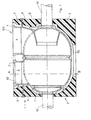
- a turbine housing 100 is shown in the figure. It is easily possible to transfer the inventive idea to a compressor housing, since the problem of temperature dissipation is the same for the two types of housing.
- the housing 100 shown in the sections according to FIGS. 1 and 2 consists of an upper shell 1 and a lower shell 2.
- the resulting housing 100 has an essentially uniform, egg-shaped shape.
- the upper shell 1 is equipped with connecting pieces 3, 4 projecting upward from the housing, the arrows showing the flow directions showing the inlet and outlet ports.
- the housing consisting of the shells 1 and 2 is surrounded by an insulating jacket 5, which consists, for example, of pressed rock wool or high-temperature resistant SiO 2 or A1 2 0 3 fibers.
- ribs, steel beams or the like are attached to the outside of the actual housing or to the connecting piece, which reach through the insulating jacket and fasten it. Such fastening ribs 6 are shown in FIG.
- Through the jacket 5 also extend the input and output shafts 19 ', 19 ", which are indicated by dashed lines in the drawing.
- a space is formed between the insulating jacket 5 and the housing and connecting piece walls 7, which serves as a cooling channel 8, which thus extends practically over the entire surface of the housing shells 1, 2.
- cooling gas openings 14 are also provided for the cooling channels in the central region, namely on the all-round joint on the longitudinal flanges between the upper and lower shell, the outside air flowing in there mixes with the convection air flow, amplifies and cools it. This improves heat dissipation.
- the cooling ducts are arranged in the area of the upper shell in such a way that they also extend along the connection pipe shell 13 and have an outlet opening 10 in the area of the pipe flange 11.
- inlet and outlet openings for the intermediate space is selected in such a way that a path with as little air resistance as possible is provided for the ascending cooling gases.
- inlet and outlet openings are all around in the area of the joint 9, d. H. in the axis plane, and in the foot area of the housing (at 12).
- a turbine housing can also be designed in such a way that main connecting pieces are present at the top and bottom.
- the cooling channels and insulating jacket of the lower shell are arranged in mirror image to that of the upper shell.
- the inlet temperature in the inlet connection 3 is 727 ° C.
- it is, for example, in the outlet connection 620 ° C.
- Temperatures occur in the interior of the housing, which are approximately between 400 ° C. and 700 ° C. It is plausible that when the insulating jacket rests directly on the outer wall of the housing, the resulting amounts of heat cannot be dissipated to a sufficient extent, so that the housing can overheat and thus shorten the stability of the turbine.
Landscapes
- Engineering & Computer Science (AREA)
- Mechanical Engineering (AREA)
- General Engineering & Computer Science (AREA)
- Turbine Rotor Nozzle Sealing (AREA)
- Structures Of Non-Positive Displacement Pumps (AREA)
Applications Claiming Priority (2)
| Application Number | Priority Date | Filing Date | Title |
|---|---|---|---|
| DE19792905564 DE2905564C2 (de) | 1979-02-14 | 1979-02-14 | Gekühltes Turbinen- oder Verdichtergehäuse |
| DE2905564 | 1979-02-14 |
Publications (2)
| Publication Number | Publication Date |
|---|---|
| EP0014941A1 true EP0014941A1 (fr) | 1980-09-03 |
| EP0014941B1 EP0014941B1 (fr) | 1982-03-31 |
Family
ID=6062875
Family Applications (1)
| Application Number | Title | Priority Date | Filing Date |
|---|---|---|---|
| EP19800100699 Expired EP0014941B1 (fr) | 1979-02-14 | 1980-02-12 | Enveloppe refroidie pour turbine ou compresseur |
Country Status (5)
| Country | Link |
|---|---|
| EP (1) | EP0014941B1 (fr) |
| JP (2) | JPS55109705A (fr) |
| BR (1) | BR8000882A (fr) |
| DE (1) | DE2905564C2 (fr) |
| MX (1) | MX149954A (fr) |
Cited By (7)
| Publication number | Priority date | Publication date | Assignee | Title |
|---|---|---|---|---|
| WO2000011324A1 (fr) * | 1998-08-18 | 2000-03-02 | Siemens Aktiengesellschaft | Carter de turbine |
| WO2003038242A1 (fr) * | 2001-10-30 | 2003-05-08 | Alstom Technology Ltd | Turbomachine |
| US7451598B2 (en) * | 2002-09-25 | 2008-11-18 | Dbt Australia Pty Limited | Turbocharged compression ignition engine |
| EP2065568A1 (fr) * | 2007-11-28 | 2009-06-03 | Siemens Aktiengesellschaft | Refroidissement d'une turbine à vapeur |
| WO2016010847A1 (fr) * | 2014-07-16 | 2016-01-21 | Borgwarner Inc. | Turbocompresseur à gaz d'échappement à enveloppe thermiquement isolée |
| CN109057887A (zh) * | 2018-09-25 | 2018-12-21 | 西安热工研究院有限公司 | 超临界工质透平壳体保温及内外对流冷却装置及其工作方法 |
| CN109083704A (zh) * | 2018-09-25 | 2018-12-25 | 西安热工研究院有限公司 | 超临界工质涡轮机组壳体保温散热装置及方法 |
Families Citing this family (1)
| Publication number | Priority date | Publication date | Assignee | Title |
|---|---|---|---|---|
| RU2230196C1 (ru) * | 2002-12-06 | 2004-06-10 | Акционерное общество открытого типа "Невский завод" | Способ защиты от перегрева корпусных деталей газовой турбины и устройство для его осуществления |
Citations (7)
| Publication number | Priority date | Publication date | Assignee | Title |
|---|---|---|---|---|
| DE367109C (de) * | 1922-02-28 | 1923-01-17 | Michael Knoerlein Dipl Ing | Luftkuehlung von Verbrennungskraftmaschinen, insbesondere Turbinen |
| DE507129C (de) * | 1927-11-27 | 1930-09-12 | Bbc Brown Boveri & Cie | Einrichtung zum Ausgleich der Waerme waehrend des Erkaltens einer ausser Betrieb gesetzten Dampf- oder Gasturbine |
| CH210654A (de) * | 1937-07-07 | 1940-07-31 | Es Ertek Talalmanykifejlesztoe | Gasturbine. |
| CH214696A (de) * | 1939-12-27 | 1941-05-15 | Maschf Augsburg Nuernberg Ag | Gasturbinenanlage. |
| CH245486A (de) * | 1944-12-22 | 1946-11-15 | Oerlikon Maschf | Verfahren zur Kühlung von Teilen einer Wärmekraftanlage. |
| CH271215A (de) * | 1950-04-28 | 1950-10-15 | Huldr Schneebeli Jac | Gasturbinenanlage. |
| CH425341A (de) * | 1965-07-23 | 1966-11-30 | Bbc Brown Boveri & Cie | Gasturbine mit Kühlung der Schaufelträger |
Family Cites Families (2)
| Publication number | Priority date | Publication date | Assignee | Title |
|---|---|---|---|---|
| DE1034924B (de) * | 1953-08-21 | 1958-07-24 | Sulzer Ag | Gasturbine mit verripptem Gehaeuse |
| JPS545921Y2 (fr) * | 1975-06-16 | 1979-03-17 |
-
1979
- 1979-02-14 DE DE19792905564 patent/DE2905564C2/de not_active Expired
-
1980
- 1980-02-12 EP EP19800100699 patent/EP0014941B1/fr not_active Expired
- 1980-02-13 BR BR8000882A patent/BR8000882A/pt not_active IP Right Cessation
- 1980-02-13 MX MX18117480A patent/MX149954A/es unknown
- 1980-02-13 JP JP1558480A patent/JPS55109705A/ja active Pending
-
1987
- 1987-09-11 JP JP1987138324U patent/JPH0329522Y2/ja not_active Expired
Patent Citations (7)
| Publication number | Priority date | Publication date | Assignee | Title |
|---|---|---|---|---|
| DE367109C (de) * | 1922-02-28 | 1923-01-17 | Michael Knoerlein Dipl Ing | Luftkuehlung von Verbrennungskraftmaschinen, insbesondere Turbinen |
| DE507129C (de) * | 1927-11-27 | 1930-09-12 | Bbc Brown Boveri & Cie | Einrichtung zum Ausgleich der Waerme waehrend des Erkaltens einer ausser Betrieb gesetzten Dampf- oder Gasturbine |
| CH210654A (de) * | 1937-07-07 | 1940-07-31 | Es Ertek Talalmanykifejlesztoe | Gasturbine. |
| CH214696A (de) * | 1939-12-27 | 1941-05-15 | Maschf Augsburg Nuernberg Ag | Gasturbinenanlage. |
| CH245486A (de) * | 1944-12-22 | 1946-11-15 | Oerlikon Maschf | Verfahren zur Kühlung von Teilen einer Wärmekraftanlage. |
| CH271215A (de) * | 1950-04-28 | 1950-10-15 | Huldr Schneebeli Jac | Gasturbinenanlage. |
| CH425341A (de) * | 1965-07-23 | 1966-11-30 | Bbc Brown Boveri & Cie | Gasturbine mit Kühlung der Schaufelträger |
Cited By (12)
| Publication number | Priority date | Publication date | Assignee | Title |
|---|---|---|---|---|
| WO2000011324A1 (fr) * | 1998-08-18 | 2000-03-02 | Siemens Aktiengesellschaft | Carter de turbine |
| US6478534B2 (en) | 1998-08-18 | 2002-11-12 | Siemnes Aktiengesellschaft | Turbine casing |
| CN1119511C (zh) * | 1998-08-18 | 2003-08-27 | 西门子公司 | 透平机壳体和避免其在关停透平机后发生弯曲变形的方法 |
| WO2003038242A1 (fr) * | 2001-10-30 | 2003-05-08 | Alstom Technology Ltd | Turbomachine |
| US6978622B2 (en) | 2001-10-30 | 2005-12-27 | Alstom Technology Ltd | Turbomachine |
| US7451598B2 (en) * | 2002-09-25 | 2008-11-18 | Dbt Australia Pty Limited | Turbocharged compression ignition engine |
| EP2065568A1 (fr) * | 2007-11-28 | 2009-06-03 | Siemens Aktiengesellschaft | Refroidissement d'une turbine à vapeur |
| WO2016010847A1 (fr) * | 2014-07-16 | 2016-01-21 | Borgwarner Inc. | Turbocompresseur à gaz d'échappement à enveloppe thermiquement isolée |
| CN109057887A (zh) * | 2018-09-25 | 2018-12-21 | 西安热工研究院有限公司 | 超临界工质透平壳体保温及内外对流冷却装置及其工作方法 |
| CN109083704A (zh) * | 2018-09-25 | 2018-12-25 | 西安热工研究院有限公司 | 超临界工质涡轮机组壳体保温散热装置及方法 |
| CN109083704B (zh) * | 2018-09-25 | 2023-10-20 | 西安热工研究院有限公司 | 超临界工质涡轮机组壳体保温散热装置及方法 |
| CN109057887B (zh) * | 2018-09-25 | 2023-12-12 | 西安热工研究院有限公司 | 超临界工质透平壳体保温及内外对流冷却装置及其工作方法 |
Also Published As
| Publication number | Publication date |
|---|---|
| EP0014941B1 (fr) | 1982-03-31 |
| DE2905564B1 (de) | 1981-01-29 |
| MX149954A (es) | 1984-02-15 |
| JPS6351102U (fr) | 1988-04-06 |
| JPH0329522Y2 (fr) | 1991-06-24 |
| BR8000882A (pt) | 1980-10-21 |
| DE2905564C2 (de) | 1981-08-27 |
| JPS55109705A (en) | 1980-08-23 |
Similar Documents
| Publication | Publication Date | Title |
|---|---|---|
| EP1032791B1 (fr) | Chambre de combustion et procede de refroidissement par vapeur d'une chambre de combustion | |
| DE602004009487T2 (de) | Dämpfungs- und Dichtungselement für Turbine | |
| DE2836539A1 (de) | Gasturbinengehaeuse | |
| EP0232782B1 (fr) | Méthode et dispositif de refroidissement des aubes de turbines thermiques | |
| EP1105623B1 (fr) | Carter de turbine | |
| DE2718661C2 (de) | Leitschaufelgitter für eine axial durchströmte Gasturbine | |
| EP2678627B1 (fr) | Refroidisseur de gaz d'échappement | |
| DE4411616C2 (de) | Verfahren zum Betreiben einer Strömungsmaschine | |
| DE2841343A1 (de) | Brennereinsatz | |
| DE2012949A1 (de) | Wandkonstruktion und Luftzufuhrlöcher für ein Gasturbinentriebwerk | |
| EP1954922B1 (fr) | Turbine a vapeur a entretoises porteuses | |
| EP0031174B1 (fr) | Aube refroidie pour turbine à gaz | |
| DE2712136A1 (de) | Gasturbinenanlage fuer den antrieb von fahrzeugen | |
| DE3228799A1 (de) | Gasturbine | |
| EP0377797B1 (fr) | Appareil de chauffage, notamment appareil de chauffage pour véhicule | |
| EP0014941B1 (fr) | Enveloppe refroidie pour turbine ou compresseur | |
| DE1938326C3 (de) | Flammrohr für ein Gasturbinentriebwerk | |
| EP2148045A1 (fr) | Section de boîtier pour une turbine à gaz | |
| DE2650922C2 (de) | Wärmetauscher zur Übertragung von in einem Hochtemperaturreaktor erzeugter Wärme an ein Zwischenkreislaufgas | |
| DE102012004954B4 (de) | Abgaskrümmer für eine Brennkraftmaschine | |
| DE102015215144B4 (de) | Vorrichtung und Verfahren zum Beeinflussen der Temperaturen in Innenringsegmenten einer Gasturbine | |
| DE3204813C2 (fr) | ||
| EP0070371A1 (fr) | Echangeur de chaleur | |
| AT402113B (de) | Brennkammer, in deren inneren ein brenner und darüber ein wärmetauscher angeordnet sind | |
| DE102017206735A1 (de) | Thermische Steuerung in einem Gehäuse mit rundem Querschnitt |
Legal Events
| Date | Code | Title | Description |
|---|---|---|---|
| PUAI | Public reference made under article 153(3) epc to a published international application that has entered the european phase |
Free format text: ORIGINAL CODE: 0009012 |
|
| AK | Designated contracting states |
Designated state(s): CH FR GB IT NL |
|
| ITCL | It: translation for ep claims filed |
Representative=s name: BARZANO' E ZANARDO MILANO S.P.A. |
|
| 17P | Request for examination filed | ||
| ITF | It: translation for a ep patent filed | ||
| GRAA | (expected) grant |
Free format text: ORIGINAL CODE: 0009210 |
|
| AK | Designated contracting states |
Designated state(s): CH FR GB IT NL |
|
| ITTA | It: last paid annual fee | ||
| REG | Reference to a national code |
Ref country code: GB Ref legal event code: 732E |
|
| PGFP | Annual fee paid to national office [announced via postgrant information from national office to epo] |
Ref country code: GB Payment date: 19990115 Year of fee payment: 20 Ref country code: FR Payment date: 19990115 Year of fee payment: 20 |
|
| PGFP | Annual fee paid to national office [announced via postgrant information from national office to epo] |
Ref country code: NL Payment date: 19990119 Year of fee payment: 20 |
|
| PGFP | Annual fee paid to national office [announced via postgrant information from national office to epo] |
Ref country code: CH Payment date: 19990201 Year of fee payment: 20 |
|
| PG25 | Lapsed in a contracting state [announced via postgrant information from national office to epo] |
Ref country code: GB Free format text: LAPSE BECAUSE OF EXPIRATION OF PROTECTION Effective date: 20000211 Ref country code: CH Free format text: LAPSE BECAUSE OF EXPIRATION OF PROTECTION Effective date: 20000211 |
|
| PG25 | Lapsed in a contracting state [announced via postgrant information from national office to epo] |
Ref country code: NL Free format text: LAPSE BECAUSE OF EXPIRATION OF PROTECTION Effective date: 20000212 |
|
| REG | Reference to a national code |
Ref country code: CH Ref legal event code: PL |
|
| REG | Reference to a national code |
Ref country code: GB Ref legal event code: PE20 Effective date: 20000211 |
|
| NLV7 | Nl: ceased due to reaching the maximum lifetime of a patent |
Effective date: 20000212 |
|
| PLBE | No opposition filed within time limit |
Free format text: ORIGINAL CODE: 0009261 |
|
| STAA | Information on the status of an ep patent application or granted ep patent |
Free format text: STATUS: NO OPPOSITION FILED WITHIN TIME LIMIT |