EP0014986A1 - Réflecteur tournant pour bicyclettes - Google Patents
Réflecteur tournant pour bicyclettes Download PDFInfo
- Publication number
- EP0014986A1 EP0014986A1 EP80100814A EP80100814A EP0014986A1 EP 0014986 A1 EP0014986 A1 EP 0014986A1 EP 80100814 A EP80100814 A EP 80100814A EP 80100814 A EP80100814 A EP 80100814A EP 0014986 A1 EP0014986 A1 EP 0014986A1
- Authority
- EP
- European Patent Office
- Prior art keywords
- revolving
- revolving reflector
- reflector
- bicycles
- bicycle
- Prior art date
- Legal status (The legal status is an assumption and is not a legal conclusion. Google has not performed a legal analysis and makes no representation as to the accuracy of the status listed.)
- Withdrawn
Links
- 230000002093 peripheral effect Effects 0.000 claims description 5
- 230000005540 biological transmission Effects 0.000 claims 2
- 239000000463 material Substances 0.000 description 9
- 229920001875 Ebonite Polymers 0.000 description 6
- 238000003466 welding Methods 0.000 description 5
- 238000010276 construction Methods 0.000 description 3
- 239000002184 metal Substances 0.000 description 2
- 229920003002 synthetic resin Polymers 0.000 description 2
- 239000000057 synthetic resin Substances 0.000 description 2
- 240000001114 Aniseia martinicensis Species 0.000 description 1
- 229910052754 neon Inorganic materials 0.000 description 1
- GKAOGPIIYCISHV-UHFFFAOYSA-N neon atom Chemical compound [Ne] GKAOGPIIYCISHV-UHFFFAOYSA-N 0.000 description 1
- 239000003973 paint Substances 0.000 description 1
- 238000007747 plating Methods 0.000 description 1
- 230000000007 visual effect Effects 0.000 description 1
Images


Classifications
-
- B—PERFORMING OPERATIONS; TRANSPORTING
- B62—LAND VEHICLES FOR TRAVELLING OTHERWISE THAN ON RAILS
- B62J—CYCLE SADDLES OR SEATS; AUXILIARY DEVICES OR ACCESSORIES SPECIALLY ADAPTED TO CYCLES AND NOT OTHERWISE PROVIDED FOR, e.g. ARTICLE CARRIERS OR CYCLE PROTECTORS
- B62J6/00—Arrangement of optical signalling or lighting devices on cycles; Mounting or supporting thereof; Circuits therefor
- B62J6/20—Arrangement of reflectors, e.g. on the wheel spokes ; Lighting devices mounted on wheel spokes
Definitions
- the present invention relates to a revolving reflector for bicycles and the like (hereafter referred to as bicycles), designed to help prevent accident at night by making the bicycles more readily visible to the drivers of cars.
- the reflectors of the first type are effective by and large from the viewpooint of the construction of bicycles, if they are properly attached to the rear fender and there is no problem in the angles of incidence and reflection in the reflectors.
- the reflectors themselves do not move, the drivers of approaching cars cannot see and recognize the relectors quickly, for example, under the following circumstances:
- the reflectors and fluorescent tapes attached to the pedals and pedal frames of bicycles of the second type are rotated together with the pedals and help the drivers of approaching cars to see and recognize the bicycle.
- their light reflection performance is " reduced significantly.
- the rider happens to wear shoes which may cover the pedals completely and make the reflectors and fluorescent tapes invisible to the drivers of cars the the reflectors and fluorescent tapes do not perform their intended function, while the rider does not notice it. Those shortcoming cannot be removed from the reflectors and fluorescent tapes of the second type.
- the reflectors attached to the spokes of the front wheels and rear wheels of bicylces of the third type make greater movement than the reflectors of the second type and are more effective in giving warnings to the car drivers than the reflectors of the first type and the second type.
- the reflectors of the third type are designed so as to be useful only when the rider crosses the road and therefore they are not readily visible to the drivers of cars approaching from behind or in front of the bicycles.
- Another object of the present invention is to provide a revolving reflector for bicycles which reflects light constantly so as to be visible to the drivers of cars at any condition.
- a further object of the present invention is to provide a revolving reflector for bicycles which is low in the cost but has a high light reflecting performance.
- a still further object of the present invention is to provide a revolving reflector for bicycles which is visible from any position.
- the revolving reflector comprises a revolving reflector member which is rotated by the wind, which reflects light, twinkling and sparkling by use of a spiral light reflecting material attached to a rotating member.
- a speed control apparatus for controlling the revolution of the rotating member, and even if the wind is weak or the bicycle is stopped, the rotating member is rotated by weak wind.
- the construction of the revolving reflector is simple and can be attached to any part of the bicycle by use of ordinary fixing parts.
- it can be attached to the hub of either wheel of the bicycle. Therefore, it is visible from any position.
- FIG. 1 there is shown an --embodiment of a revolving reflector for bicycles according to the invention.
- reference numeral 1 represents a main frame of the revolving reflector.
- the main frame 1 is made of a crosswise cut square pipe and a fixture la is fixed to the main frame by welding or ribets.
- a hole lb In the fixture la, there is formed a hole lb for allowing a bolt to pass therethrough in order to fix the main frame 1 to the bicycle.
- a rotation control drum 3 In an upper space within the main frame 1, there is disposed pivotally a rotation control drum 3, and in a lower space within the main frame 1, there is disposed pivotally a revolving reflector plate 2.
- Fig. 2 is a partly fragmentary view of the revolving reflector of Fig. 1 for a better understanding of its construction.
- a shoulder screw 4 which serves as a bearing, is caused to pass through the hole lc and a hole 3' formed in the central portion of the rotation control control drum 3 and is fixed to the main frame 1 by a nut 5.
- a shoulder scew 4a which also serves as a bearing, is likewise caused to pass through the hole ld and is fixed to the main frame 1 by a nut 5'.
- the revolving reflector plate 2 is disposed in the following manner.
- a top portion and a bottom portion of the revolving reflectc 2 on its vertical axis are respectively inserted tightly into the slots formed in shafts 2a, 2b, and in the shafts 2a, 2b, there are formed spot facings 4', 4a', respectively, and projected portions of the shoulder screws 4, 4a are fitted into the spot facings 4', 4a', so that the revolving reflector plate 2 can be rotated smoothly on the projected portions of the shoulder screws 4, 4d through the shafts 2a, 2b.
- the opposite sides of the revolving reflector plate 2 are curved in the opposite directions so as to be rotated efficiently in the wind.
- a speed control means for controlling the rotation of the revolving reflector plate 2 so as not to be revolved too fast in strong wind or when the speed of the bicycle is increased.
- the rotation of the reflector plate 2 is controlled by use of the centrifugal force generated when the revolving reflector plate 2 is revolted too fast.
- a spiral spring 3a is fixed to a top portion of the shaft 2a by a screw, and when the revolving reflector plate 2 is rotated too fast, the spiral spring 3a is pushed away from its center and its outer surface is brought into contact with the inner surface of the rotation control drum 3, so that the rotation of the revolving reflector plate 2 is controlled by the friction of the spiral spring 3a against the inner surface of the rotation control drum 3.
- a piece of hard rubber 3b in order to increase the centrifugal force of the spiral spring 3a as well as its speed control performance.
- the psiral spring 3a is entirely built in the rotation control drum 3.
- the elastic strength of the spiral spring 3a is adjusted in such a manner that the hard rubber 3b is positioned away from the inner surface of the rotation control drum 3 during normal rotation of the revolving reflector plate 2.
- one side of the revolving reflector plate 2 is plated to reflect light effectively and the other side is coated with a fluorescent paint. It will be more preferable that vh the reflector plate 2 be made of such a reflector as is used in the tail reflectors of cars.
- FIGs. 3 there is shown another rotation control device for controlling the rotation of the reflector plate 2, which corresponds to the spiral spring 3a in the above-mentioned embodiment.
- spring plates 3a', 3b' are fixed by screws to the opposite outer sides of the shaft 2a.
- Fig. 3 particularly shows perspectively the speed control device in operation.
- a further rotation control device for controlling the rotation of the reflector 2.
- the end portions of spring plates 6. 6( are attached to the opposite sides 2c, 2d of the reflector plate 2 whose opposite sides are bent in the opposite directions for effective rotation by the wind and hard rubber pieces 6a, 6b which are embedded respectively in the other end portions of the spring plates 6, 6'.
- the reflector plate 2 is rotated at a speed beyond a predetermined limit, the spring plates 6, 6' are moved outwards by centrifugal force, so that the hard rubber pieces 6a, 6b of the spring plates 6, 6' are caused to strike against the inner surface of the main frame 1 shown in Fig. 2.
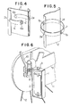
- Fig. 5 shows a still further rotation control device.
- the spring plates 6, 6' in Fig. 4 are replaced with a ring-shaped member which is represented by reference number 7.
- the ring member 7 is fixed to the revolving reflector 2 by welding or rivets at the opposite side portions 2e, 2f of the reflector plate 2, and at the central portions of the ring member 7 between the fixed portions thereof, there are embedded hard rubber pieces 7a, 7b.
- the ring member 7 becomes oval in the shape by centrifugal force and the hard rubber pieces 7a, 7b come into contact with the inner surface of the main frame 1, so that the rotation of the reflector plate 2ds controlled.
- the spring plates as mentioned above are selected such that they do not control the rotation of the revolving reflector plate 2 when the relector plate 2 is in normal rotation, from the viewpoint of the kind of material, thickness and width of the spring plate and the centrifugal force applied to the spring plates during the rotation of the reflector plate 2.
- Fig. 6 shows how the embodiment of the revolving reflector for bicycles as shown in Figs. 1 and 2 is attached to the bicycle in practice.
- the main frame 1 of the revolving reflector is attached to a shaft 8 of the rear wheel of a bicycle.
- the revolving reflector according to the invention can be attached to any portion of the bicycle as long as it is safe and suitable for the reflection of light from the reflector.
- Fig. 6 shows how the embodiment of the revolving reflector for bicycles as shown in Figs. 1 and 2 is attached to the bicycle in practice
- reference numeral 1 represents the main frame of the revolving reflector
- reference numeral 8 the shafts of the rear wheel of the bicycle
- reference numeral 8a a nut for fastening the shaft 8 of the rear wheel
- reference numeral 9 the body of the bicycle
- reference numeral 10 a support member for supporting a luggage-carrier
- reference numeral 11 a chain guard
- Fig. 7 is a perspective view of another embodiment of a revolving reflector for bicycles according to the invention, which includes a partial broken view of the revolving reflect
- a revolving reflector plate 14 is also rotated by the wind.
- the rotation shaft of the revolving reflector plate 14 is disposed horizontally.
- the attachment portion is S-shaped so that the revolving reflector can be attached to any type of bicycles.
- the revolving refelector plate 14 is pivotally mounted on a shaft 14e which is embedded into a central portion of the revovling reflector plate 14.
- the opposite end portins 14a, 14b of the revolving reflector plate 14 are curved as shown in Fig. 7 so that the reflector plate 14 is rotated by the wind when one rides the bicycle.
- reference numerals 14, 14d each represent bearing holes of the reflector plate 14.
- the revolving reflector plate 14 can be made of metal or synthetic resin.
- the reflector plate 14 can be made of a reflection mirror for cars, which reflects light intensely when it is illuminated by head light of cars at night.
- the reflection mirror is shown by cross stripes.
- the main frame 13 of the revolving reflector can be attached to any portion of the bicycle as long as it is safe and a sufficient wind for the rotation of the revolving reflector plate 14 can be obtained and a high light reflecting performance can be obtained.
- a main frame 15 of the revolving reflector is a ring which can be made, for example, by cutting crosswise a pipe.
- An attachment member 15a is fixed to the. main frame 15 by welding or rivets and inside the main frame 15, the propeller-like reflector plate 17 is rotatably disposed.
- the reflector plate 17 can be made of metal or synthetic resin and the front and back sides of a half portion of the propeller-like plate are made of the previously mentioned reflection mirror for cars.
- the thus constructed reflector plate 17 is pivotally mounted on. a bearing 16 and is supported by the main frame through a bearing support member 16a.
- Fig. 9 shows perspectively a still further embodiment of a revolving reflector for bicycles according to the invention.
- a revolving reflector plate 19 is rotated by the rotation of a wheel of bicycle, unlike the so-far explained revolving reflector plates which are rotated by the wind. Since a main frame 18 of the revolving reflector is the same as the main frame 1 in the embodiment of Figs. 1 and 2, its explanation is omitted here.
- the revolving reflector plate 19 is made in such a shape and size so as to be rotatable inside the main frame 18 and one side of the reflector plate 19 is finished like a mirror, for example, by plating, and the other side of the reflector plate 19 is made of the previously mentioned reflection mirror for cars or the reflection mirror is fixed to the other side of the revolving reflector plate 19.
- the thus-constructed revolving reflector plate 19 is fixed to shafts 19a, 19b in the same manner as in the case of the revolving reflector in Figs. 1 and 2. More specifically, a top portion and bottom portion of revolving reflector 19 on its vertical axis are respectively inserted tightly into the slots formed in the shafts 19a, 19b.
- a flexible shaft 21 is inserted into the shaft 19b and is supported rotatably in association with an upper bearing 20.
- the flexible shaft 21 passes through a protecting cable 21a.
- the other end of the flexible shaft 21 is connected to a speed meter which is attached to bicycles for sports, so as to follow the rotation of a wheel of the bicycle.
- a speed meter which is attached to bicycles for sports, so as to follow the rotation of a wheel of the bicycle.
- threads which engage with a knurled screw 21b which is attached to an end portion of the protecting cable 21a of the flexible shaft 21.
- FIG. 10 shows perspectively a further embodiment of a revolving relector for bicycles according to the invention, in which a revolving reflector is rotated by the wind.
- reference numeral 51 represents a main frame of the revolving reflector which is approximately in the shape of topped U.
- a central portion ofihe main frame 51 there is further formed a smaller toppled U-shaped portion in which an attachment hole 52 is formed.
- a bearing 53 To an end portion of an upper portion of the main frame 51, there is fixed a bearing 53 by a screw.
- To an end portion of a lower portion of the main frame 51 there is also fixed a bearing in the same manner as mentioned above.
- Inside the main frame 51 there is disposed rotatably rotating member between the above-mentioned upper bearing 53 and the lower bearing. The rotating member is rotated by the wind when the bicycle is running.
- FIG. 11 is a plan view of Fig. 10.
- reference numeral 54 represents a cyclinder to which peripheral surface of a spiral light reflecting material 54a having a predetermined width is attached.
- Reference numerals 55, 56 and 57 each represent wind receiving blades in the shape of a circular arc in their respective vertical directions.
- the wind receiving blades 55, 56, 57 are supported by the cylinder 54 and their upper portions are inserted into grooves 58b of a disc 58 and fixed thereto by welding, and their lower portions are also inserted into grooves 58b of a disc 58a and fixed thereto by welding.
- each of the discs 58, 58a there is further formed a hole, and a shaft which is longer than the cylinder 54 is passed through the holes and fixed thereto in a manner such that the opposite ends of the shaft are projected from the discs 58, 58a by an equal length.
- the wind receiving blades 55, 56, 57 are arranged in the same direction, so that inihis embodiment, the cylinder 54 is rotated clockwise by the wind.
- Fig. 12 perspectively shows a further embodiment of a revolving reflector for bicycles according to the invention. Also in this revolving reflector, a revolving reflector member is rotated by the wind.
- reference numeral 60 represents a main frame of the revolving reflector, which has an attachment hole 61 for attaching the revolving reflector to part of a bicycle.
- the whole shape of the main frame 60 is shaped like a quarter of a Silocco fan when it is viewed from the shaft of the fan.
- - bearings 62, 62a are fixed respectively by screws.
- a cylinder 63 around which a reflecting material is wound in spiral is disposed in a window 67 positioned in a central portion of a rotating member 64, and the rotating member 64 is pivotally mounted so as to be readily rotated by the wind which blows in the direction of the arrow in Fig. 12.
- Fig. 13 shows an enlarged perspective view of the rotating member 64.
- the rotating member 64 constitutes a wind receiving blade whose opposite side portions 64a, 64b are curved as shown in Fig. 13.
- To an uppermost portion and a lowermost portion on the vertical central axis of the rotating member 64 there are fixed respectively shafts 65; 65' by press fits 65a, 65b.
- a star mark represents a light reflecting material to be sticked on the rotating member-64.
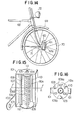
- Fig. 14 shows how to attach the revolving reflector as shown in Figs. 12 and 13 to a bicycle in practice.
- reference numeral 60 represents the main frame of the revolving reflector.
- the revolving reflector is fixed to the shaft of a front wheel of the bicycle by screws, utilizing the nut of the shaft.
- the rotating member 64 is rotated by the wind.
- the light reflecting material has a visual effect as if it moves upwards so that it is readily visible to the car drivers.
- the body of the bicycle is designated 68, a front fender 69, a tire 70, spokes 71, and a lamp 72.
- a main frame of the revolving reflector is designated 101, which has an attachment portion 102 for attaching the main frame 101 to part of the bicycle.
- attachment portion 102 there is formed an attachment hole 103.
- the main frame is in the shape of a crosswise cut square pipe.
- a screw hole In the central portion each of an upper and a lower portion of the main frame 101, there is formed a screw hole in which a conic bearing 104 can be screwed.
- the conic bearings are screwed'in the screw holes and fixed thereto by nuts 105 in both the upper and the lower portion of the main frame 101. Between both the conic bearings 104, there is rotatably disposed a rotating member.
- reference numeral 106 represents a cylinder having, on its peripheral surface, a spiral light reflecting material 107.
- the opposite upper and lower ends of the cylinder 106 are fixed to an upper disc 111 and a lower disc 112.
- the upper and lower discs lll, 112 there are embedded the opposite ends of wind receiving blades 108, 109, 110,which are disposed at an equal space therebetween parallel to a generating line of the cylinder 106.
- a shaft having sharp ends is disposed so as to pass through the central portions of the upper disc 11 and the lower disc 112 and to be fixed thereto, projecting from the upper and lower discs 111, 112 by an appropriate length.
- the cylinderl06 is supported by the conic bearings 104 between the upper and lower discs 111, 112 in the manner of anti-friction.
- Fig. 16 is a section taken on line A-A in Fig. 14.
- the wind receiving blades 108, 109, 110 are rectangular in the shape and are bent almost at right angle in the direction of their longitudinal axis.
- FIG. 17 there is perspectively shown a further embodiment of a revolving reflector of the type which is revolved by the wind according to the invention.
- reference numeral 114 represents a support member for supporting a rotating member, one end of which serves as a shaft having a sharp end as well and in which a groove for a retaining ring is formed, and the other end of which has an attachment hole for attaching the revolving reflector to part of a bicycle.
- Reference numeral 116 represents a cylinder having a spiral light reflecting material 117 on the peripheral surface of the cylinder 116, numerals 118, 119 and 120 each represent wind receiving blades, and numerals 121 and 122 represent members equivalent to the upper disc 111 and the lower disc 112 in Figs. 15 and 16.
- a conic bearing is embedded in a central portion of the bottom of the conic head portion represented by the numeral 121.
- One end of the shaft having the sharp end support member 114 is passed through the center of the skirt-like disc represented by the numeral 122, so that the cylinder 116 is supported by the above-mentioned bearing and the shaft in such a:manner of anti-friction.
- the retaining ring is provided so as to be rotatable in the groove formed in the support member 114 on the bottom side of the skirt-like disc 122.
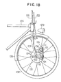
- Fig. 18 shows how to attach the revolving reflector as shown in Figs. 15 and 16 to a bicycle.
- the revolving reflector is attached to the right side of the front wheel of the bicycle.
- the numeral 101 represents a support member for supporting the rotatable member
- numeral 102 represents an attachment member for attaching the support member 101 to part of the bicycle.
- the support member 101 is fixed to the shaft 123 of the front wheel by passing the support.member 101 through the attachment hole 102, using a nut 124.
- a portion represented by the numeral 106 is a cylinder having a light reflecting material on its surface.
- Numerals 108, 110 and 109 represent wind receiving blades.
- Numeral 111 represents an upper disc, and numeral 112 a lower disc. Furthermore, the body of the bicycle is designated 125, a handle 126, fork blades of the front wheel 127, a front fender 128, a lamp 129, a tire 130, spokes 131, and a brake rod 132.
- Fig. 19 shows a further ,embodiment of the invention.
- a main frame 151 is designated 151, which is shaped like a crosswise cut square pipe.
- the main frame 151 has an attachment member 125 on one longer side thereof.
- an attachment hole 153 for attaching the revolving reflector to part of a bicycle therethrough.
- a rotating member is disposed inside the main frame 151. The rotating member will now be explained in reference to Fig. 19.
- wind receiving blades are designated 154, 155 and 156, which have light reflecting surfaces 154', 155' and 156' (cross lined portions in Fig. 19) whose positions are shifted in the axial direction of the wind receiving blades.
- the wind receiving blades are convex in the wind receiving direction.
- the upper ends and the lower ends of the wind receiving blades 154, 155, 156 are embedded in a ' disc 159 in which a shaft 157 is also embedded and in a disc 160 in which a shaft 158 is also embedded, respectively.
- the shafts 157, 158 are sharp in the other ends thereof.
- the thus constructed rotating member is attached to the main frame 151 in the following manner.
- a screw hole whose diameter is the same as the threads formed in an outer portion of a conic bearing 161.
- the conic bearing 161 is screwed in the above-mentioned screw hole and is fixed to the main frame 151 by a nut 163.
- Fig. 20 is a section taken on line A-A in Fig. 19, viewed from the direction of the arrow at the line A-A.
- the main frame is designated 151 and 152, the wind receiving blades 154, 155 and 156, and the disc 160.
- the wind receiving blade 154 a cross section of the previously mentioned light reflecting surface 154' is indicated, while in the wind receiving blade 155, a cross section of the convex wind receiving blade and an upper portion of the lower light reflecting surface.
- the wind receiving blade 156 only its convex cross section is indicated.
- the wind receiving blades 154, 155, 156 are embedded in the disc 160 with an equal space and an equal angle therebetween radially from the center of the disc 160.
- the convex portions of the blades 154, 155, 156 are arranged in the same direction, namely clockwise in this embodiment.
- Fig. 21 shows how to attach the revolving reflector as shown in Figs. 19 and 20 to part of a bicycle.
- the attachment hole 153 of the main frame 151 is fitted to a shaft portion of the front wheel on its right side and is fixed thereto by a nut.
- the axial direction of the revolving reflector is set so as to be vertical position, perpendicular to the ground, whereby the friction between the shafts 157, 158 having sharp ends and the conic bearings 161, 162 is reduced, so that the rotating member can be rotated by a-weak wind.
- the concave sides of the wind receiving blades 154, 155, 156 are directed against the wind, so that the rotating member is rotated clockwise.
- the main frame of the revolving reflector is designated 151 and 152, the shaft of a front wheel 164, a nut of the shaft 164', spokes 165, the fork blades 166, the rim 167, the tire 168, and body of the bicycle 169.
Landscapes
- Engineering & Computer Science (AREA)
- Mechanical Engineering (AREA)
- Lighting Device Outwards From Vehicle And Optical Signal (AREA)
Applications Claiming Priority (8)
| Application Number | Priority Date | Filing Date | Title |
|---|---|---|---|
| JP20020/79 | 1979-02-19 | ||
| JP2002079U JPS55119285U (fr) | 1979-02-19 | 1979-02-19 | |
| JP7097579U JPS55170190U (fr) | 1979-05-26 | 1979-05-26 | |
| JP70975/79 | 1979-05-26 | ||
| JP105044/79 | 1979-07-30 | ||
| JP10504479U JPS5622179U (fr) | 1979-07-30 | 1979-07-30 | |
| JP15853279U JPS5675081U (fr) | 1979-11-15 | 1979-11-15 | |
| JP158532/79 | 1979-11-15 |
Publications (1)
| Publication Number | Publication Date |
|---|---|
| EP0014986A1 true EP0014986A1 (fr) | 1980-09-03 |
Family
ID=27457299
Family Applications (1)
| Application Number | Title | Priority Date | Filing Date |
|---|---|---|---|
| EP80100814A Withdrawn EP0014986A1 (fr) | 1979-02-19 | 1980-02-18 | Réflecteur tournant pour bicyclettes |
Country Status (1)
| Country | Link |
|---|---|
| EP (1) | EP0014986A1 (fr) |
Cited By (10)
| Publication number | Priority date | Publication date | Assignee | Title |
|---|---|---|---|---|
| GB2124281A (en) * | 1982-02-19 | 1984-02-15 | Peter Robert Eric Picton | A reflector |
| US4479699A (en) * | 1981-03-12 | 1984-10-30 | Richard Bolte | Wind driven rotatable reflector for vehicles |
| US4747664A (en) * | 1985-04-29 | 1988-05-31 | Slaughter Harold W | Rotary reflective marker |
| US4767185A (en) * | 1986-12-15 | 1988-08-30 | Lyons Terry B | Rotating multicolored air driven reflector |
| US4852970A (en) * | 1988-01-21 | 1989-08-01 | Kitrell John V | Visual signal device for a bicycle |
| US4852971A (en) * | 1988-01-21 | 1989-08-01 | Kitrell John V | Fender mounted visual signal device for a bicycle |
| US5014641A (en) * | 1990-09-10 | 1991-05-14 | Johnson William M | Hazard warning device for vehicles |
| US5349920A (en) * | 1992-12-23 | 1994-09-27 | Toshio Koizumi | Safety reflector marker |
| WO1995005967A1 (fr) * | 1993-08-26 | 1995-03-02 | 'see Me' Sprl | Catadioptre rotatif arriere pour cycles |
| GB2287975A (en) * | 1994-03-31 | 1995-10-04 | Peter Robert Eric Picton | A reflector |
Citations (5)
| Publication number | Priority date | Publication date | Assignee | Title |
|---|---|---|---|---|
| US2701540A (en) * | 1953-07-09 | 1955-02-08 | Hamilton Neil | Warning signal and method of manufacturing thereof |
| US3758190A (en) * | 1972-05-08 | 1973-09-11 | Nu Pro Inc | Jumping reflex-reflection |
| DE2544957A1 (de) * | 1974-10-11 | 1976-04-22 | Norbert A Kirk | Reflektor fuer fahrraeder |
| US4103924A (en) * | 1976-12-06 | 1978-08-01 | Suhm Richard R | Vehicle safety device |
| US4105286A (en) * | 1977-01-27 | 1978-08-08 | Curran Mike H | Bicycle reflector assembly |
-
1980
- 1980-02-18 EP EP80100814A patent/EP0014986A1/fr not_active Withdrawn
Patent Citations (5)
| Publication number | Priority date | Publication date | Assignee | Title |
|---|---|---|---|---|
| US2701540A (en) * | 1953-07-09 | 1955-02-08 | Hamilton Neil | Warning signal and method of manufacturing thereof |
| US3758190A (en) * | 1972-05-08 | 1973-09-11 | Nu Pro Inc | Jumping reflex-reflection |
| DE2544957A1 (de) * | 1974-10-11 | 1976-04-22 | Norbert A Kirk | Reflektor fuer fahrraeder |
| US4103924A (en) * | 1976-12-06 | 1978-08-01 | Suhm Richard R | Vehicle safety device |
| US4105286A (en) * | 1977-01-27 | 1978-08-08 | Curran Mike H | Bicycle reflector assembly |
Cited By (12)
| Publication number | Priority date | Publication date | Assignee | Title |
|---|---|---|---|---|
| US4479699A (en) * | 1981-03-12 | 1984-10-30 | Richard Bolte | Wind driven rotatable reflector for vehicles |
| GB2124281A (en) * | 1982-02-19 | 1984-02-15 | Peter Robert Eric Picton | A reflector |
| US4747664A (en) * | 1985-04-29 | 1988-05-31 | Slaughter Harold W | Rotary reflective marker |
| US4767185A (en) * | 1986-12-15 | 1988-08-30 | Lyons Terry B | Rotating multicolored air driven reflector |
| US4852970A (en) * | 1988-01-21 | 1989-08-01 | Kitrell John V | Visual signal device for a bicycle |
| US4852971A (en) * | 1988-01-21 | 1989-08-01 | Kitrell John V | Fender mounted visual signal device for a bicycle |
| US5014641A (en) * | 1990-09-10 | 1991-05-14 | Johnson William M | Hazard warning device for vehicles |
| US5349920A (en) * | 1992-12-23 | 1994-09-27 | Toshio Koizumi | Safety reflector marker |
| WO1995005967A1 (fr) * | 1993-08-26 | 1995-03-02 | 'see Me' Sprl | Catadioptre rotatif arriere pour cycles |
| AU683292B2 (en) * | 1993-08-26 | 1997-11-06 | "See Me" Sprl | Rotary rear reflector for cycles |
| GB2287975A (en) * | 1994-03-31 | 1995-10-04 | Peter Robert Eric Picton | A reflector |
| GB2287975B (en) * | 1994-03-31 | 1997-09-17 | Peter Robert Eric Picton | A reflector |
Similar Documents
| Publication | Publication Date | Title |
|---|---|---|
| EP0014986A1 (fr) | Réflecteur tournant pour bicyclettes | |
| US4176390A (en) | Light | |
| US6857709B1 (en) | Non-rotating wheel cover | |
| US4121851A (en) | Spinner for bike hub | |
| US5800039A (en) | Warning device for bicycle having changeable patterns | |
| US3924928A (en) | Attachment for reflectors for spoke wheels | |
| US6709138B1 (en) | Tire with fluorescent tread and tread wear indicators | |
| US6860368B2 (en) | High friction brake shoe assembly | |
| US4103924A (en) | Vehicle safety device | |
| US5652677A (en) | Light reflecting bicycle safety apparatus | |
| US4105286A (en) | Bicycle reflector assembly | |
| WO1992003301A1 (fr) | Ensemble enjoliveur de roue | |
| GB2101541A (en) | Wheel rims | |
| US5121972A (en) | Device for cooling vehicle brake area | |
| US5287221A (en) | Dynamic flashing reflector rotatably mounted on vehicle wheel | |
| US5014641A (en) | Hazard warning device for vehicles | |
| US6789925B1 (en) | Lighting apparatus for bicycles | |
| US5349470A (en) | Spoked wheel reflective vest for bicycles and the like | |
| US4289376A (en) | Light reflectors | |
| US20070222179A1 (en) | Bicycle Wheel Spinner Assembly | |
| US4648694A (en) | Bicycle wheel safety attachment | |
| US20050093362A1 (en) | Oscillating wheel accessory | |
| US4047800A (en) | Bicycle reflector device | |
| US5361718A (en) | Reflective warning device for wheeled vehicles | |
| US11485438B2 (en) | Visible safely bicycle |
Legal Events
| Date | Code | Title | Description |
|---|---|---|---|
| PUAI | Public reference made under article 153(3) epc to a published international application that has entered the european phase |
Free format text: ORIGINAL CODE: 0009012 |
|
| AK | Designated contracting states |
Designated state(s): DE FR GB NL |
|
| STAA | Information on the status of an ep patent application or granted ep patent |
Free format text: STATUS: THE APPLICATION IS DEEMED TO BE WITHDRAWN |
|
| 18D | Application deemed to be withdrawn |
Effective date: 19811118 |