EP0015280B1 - Verfahren und vorrichtung zum abschneiden länglicher hohler elemente - Google Patents
Verfahren und vorrichtung zum abschneiden länglicher hohler elemente Download PDFInfo
- Publication number
- EP0015280B1 EP0015280B1 EP79900788A EP79900788A EP0015280B1 EP 0015280 B1 EP0015280 B1 EP 0015280B1 EP 79900788 A EP79900788 A EP 79900788A EP 79900788 A EP79900788 A EP 79900788A EP 0015280 B1 EP0015280 B1 EP 0015280B1
- Authority
- EP
- European Patent Office
- Prior art keywords
- milling cutter
- cutting
- cut
- rotating
- during
- Prior art date
- Legal status (The legal status is an assumption and is not a legal conclusion. Google has not performed a legal analysis and makes no representation as to the accuracy of the status listed.)
- Expired
Links
- 238000000034 method Methods 0.000 title claims description 8
- 238000003801 milling Methods 0.000 claims abstract description 41
- 230000008878 coupling Effects 0.000 description 3
- 238000010168 coupling process Methods 0.000 description 3
- 238000005859 coupling reaction Methods 0.000 description 3
- 230000033001 locomotion Effects 0.000 description 3
- 230000005540 biological transmission Effects 0.000 description 1
- 230000003247 decreasing effect Effects 0.000 description 1
- 238000005553 drilling Methods 0.000 description 1
- 238000004519 manufacturing process Methods 0.000 description 1
- 238000012986 modification Methods 0.000 description 1
- 230000004048 modification Effects 0.000 description 1
Images


Classifications
-
- B—PERFORMING OPERATIONS; TRANSPORTING
- B23—MACHINE TOOLS; METAL-WORKING NOT OTHERWISE PROVIDED FOR
- B23D—PLANING; SLOTTING; SHEARING; BROACHING; SAWING; FILING; SCRAPING; LIKE OPERATIONS FOR WORKING METAL BY REMOVING MATERIAL, NOT OTHERWISE PROVIDED FOR
- B23D21/00—Machines or devices for shearing or cutting tubes
- B23D21/04—Tube-severing machines with rotating tool-carrier
Definitions
- the present invention relates to a method for cutting off elongated hollow elements, such as tubes, wherein the element is inserted through a milling cutter having inwardly directed cutting means, the milling cutter is rotated relative to the element and the element and the milling cutter are maintained in fixed mutual axial interrelationship during the cut-off operation.
- the invention also relates to a device for cutting off elongated hollow elements, which comprises a milling cutter having a plurality of cutting means directed radially inwards, means for rotating the milling cutter and means for rotating the elongated element.
- the invention is particularly intended to be used in connection with oil drilling, where the well is supported by casings, i.e. tubes, having diameters ranging from about 10 to 90 centimeters.
- casings i.e. tubes, having diameters ranging from about 10 to 90 centimeters.
- the tubes have a length of 10 to 12 meters and are provided with external threads at each end.
- the tubes are mutually interconnected by means of internally threaded coupling sleeves.
- the coupling sleeves are manufactured by cutting off blanks from long (in the order of 10 to 12 meters) tubes, which blanks are machined on specially designed machines.
- the cut-off operation is a problem area in the manufacturing of the coupling sleeves. It has been suggested to rotate and cut off the tubes by means of a stationary cut-off tool. Due to the length and out-of roundness of the tubes, the cutting speed is limited. Further, the tools are often damaged by the tube element being cut at the moment when the tools break through the wall of the tube.
- US-A-1063789 discloses a machine for cutting off elongated elements by using a milling cutter having a plurality of cutting means directed radially inwards.
- the milling cutter is slidably mounted for cut-off movement. During the cut-off operation the elongated element is stationary.
- US-A-2247582 discloses a machine for milling external cylindrical surfaces.
- the machine comprises a milling cutter having inwardly directed cutting means. During the milling operation both the cutter and the cylindrical element are rotated. The required feeding movement of the milling cutter is obtained by a swingable support thereof.
- the present invention relates basically to a machine of the last-mentioned type and the object of the present invention is to provide a method and a device for cutting off tubes, where a comparatively high cutting speed can be used while simultaneously giving a smoother cutting and less risks for damage to the equipment and to the tube element being cut.
- a milling cutter of a type known per se, for instance by DE-A-1752091 is used in which the cutting edges of the cutting means are positioned in staggered axial interrelationship so that some of the cutting edges cut different zones than other cutting edges.
- Fig. 1 shows a top view of a device according to the embodiment of the invention.
- Fig. 1 shows a tube 10 mounted in a cut-off machine 11.
- the machine comprises holders 12 and 13 with rotatable chucks 14 for gripping the tube.
- the chucks 14 are driven in synchronism by motors 15.
- a guide bed 16 on which is slidably mounted a cutter housing 17 carrying a milling cutter 18.
- the cutter is rotated by a motor 19 and the housing 17 is moved along the guide bed 16 by a motor 20 through a screw transmission 21.
- the guide bed 16 is plane but the transverse motion of the cutter may have some other shape, for instance curved or circular.
- Fig. 3 shows the cutter 18 with a number of the insert sites.
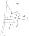
- Each site comprises a recess containing a backing up shim plate 22, a cutting insert 23 and a clamping screw 24 with a clamping wedge 25.
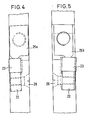
- the cutting inserts 23 are mounted in a staggered mutual interrelationship so that every other insert cuts about half of the thickness of the cut and every other insert cuts the other half, the halves slightly overlapping in the middle. This is illustrated in Figs. 4 and 5.
- the insert sites are orientated slightly obliquely together with the inserts 23 and the shims 22.
- the shims are fastened with screws 26.
- the wedges 25 are of two different types, 25a and 25b, depending on which side they are placed on.
- the cutting of a tube is carried out as described below.
- the tube 10 is positioned as shown in Fig. 1 and clamped by the chucks 14.
- the milling cutter 18, then, is rotated in counter-clockwise direction in Fig. 2 as indicated by arrow A by means of the motor 19.
- the milling cutter 18 is moved laterally by means of the motor 20 during the rotation of the milling cutter.
- the tube 10 is maintained stationary till the milling cutter 18 has cut through the wall of the tube 10.
- the motors 15 are started, thereby rotating the tube 10 slowly in clockwise direction in Fig. 2 as indicated by arrow B.
- the tube 10 is rotated till the cut-off around the whole tube is completed.
- the milling cutter is maintained stationary in its lateral position.
- the tube 10 and the milling cutter 18 are rotated simultaneously during the whole cut-off operation.
- the milling cutter 18 is moved laterally during the rotation of the milling cutter and the tube.
- the milling cutter 18 and the tube 10 have opposite rotational directions. According to the invention, however, the milling cutter and the tube can have the same rotational direction.
- the rotational speeds of the milling cutter and the tube and the speed of the lateral feed mechanism 20, 21 for the milling cutter are preferably adjusted in mutual relationship for obtaining optimal cutting with as small vibrations as possible.
- the rotational speed of the milling cutter shall be preferably much higher than the rotational speed of the tube. It is believed that the ratio therebetween should be larger than 50, with preference for values in the order of 60-120, in cases where the ratio between the diameters of the tube and the milling cutter is larger than 0.7.
- the ratio between the rotational speeds can be decreased in proportion to the decrease of the diameter of the tube.
- a cutting speed of 120 m/min i.e. a rotational speed of about 340 rpm when the diameters of the tube and the milling cutter are respectively 0.5 and 0.7 meter
- a rotational speed of the tube of about 3 rpm are believed to be suitable.
Landscapes
- Engineering & Computer Science (AREA)
- Mechanical Engineering (AREA)
- Milling Processes (AREA)
- Turning (AREA)
- Sawing (AREA)
Claims (8)
Applications Claiming Priority (2)
| Application Number | Priority Date | Filing Date | Title |
|---|---|---|---|
| DE2829762 | 1978-07-06 | ||
| DE19782829762 DE2829762A1 (de) | 1978-07-06 | 1978-07-06 | Verfahren und vorrichtung zum abstechen von rohren o.dgl. |
Publications (2)
| Publication Number | Publication Date |
|---|---|
| EP0015280A1 EP0015280A1 (de) | 1980-09-17 |
| EP0015280B1 true EP0015280B1 (de) | 1982-10-06 |
Family
ID=6043735
Family Applications (1)
| Application Number | Title | Priority Date | Filing Date |
|---|---|---|---|
| EP79900788A Expired EP0015280B1 (de) | 1978-07-06 | 1980-02-12 | Verfahren und vorrichtung zum abschneiden länglicher hohler elemente |
Country Status (4)
| Country | Link |
|---|---|
| EP (1) | EP0015280B1 (de) |
| JP (1) | JPS55500505A (de) |
| DE (2) | DE2829762A1 (de) |
| WO (1) | WO1980000138A1 (de) |
Families Citing this family (1)
| Publication number | Priority date | Publication date | Assignee | Title |
|---|---|---|---|---|
| DE8910709U1 (de) * | 1989-09-08 | 1991-01-17 | Waiko Möbelwerke GmbH & Co KG, 7071 Durlangen | Zerlegbare Schrankwand mit einem Profil aus Metall und Beschlagteilen |
Family Cites Families (4)
| Publication number | Priority date | Publication date | Assignee | Title |
|---|---|---|---|---|
| US2247582A (en) * | 1940-06-19 | 1941-07-01 | Ingersoll Milling Machine Co | Method of and machine for milling |
| CH427459A (de) * | 1959-09-09 | 1966-12-31 | Ernst Dr Techn Linsinger | Verfahren zum Umfangsfräsen unter Verwendung von hartmetallbestückten Fräsern und Fräsmaschine zur Durchführung des Verfahrens |
| DE1752091A1 (de) * | 1968-04-02 | 1970-03-05 | Karl Burgsmueller | Vorrichtung zur spanabhebenden Bearbeitung von Kurbellagerstellen od.dgl.unter Verwendung eines Wirbelhohlkreisels |
| US4116095A (en) * | 1977-08-05 | 1978-09-26 | Cousino Walter F | Metal sawing or milling machine |
-
1978
- 1978-07-06 DE DE19782829762 patent/DE2829762A1/de not_active Withdrawn
-
1979
- 1979-07-06 WO PCT/SE1979/000148 patent/WO1980000138A1/en not_active Ceased
- 1979-07-06 JP JP50110279A patent/JPS55500505A/ja active Pending
- 1979-07-06 DE DE7979900788T patent/DE2963809D1/de not_active Expired
-
1980
- 1980-02-12 EP EP79900788A patent/EP0015280B1/de not_active Expired
Also Published As
| Publication number | Publication date |
|---|---|
| WO1980000138A1 (en) | 1980-02-07 |
| DE2963809D1 (en) | 1982-11-11 |
| JPS55500505A (de) | 1980-08-07 |
| DE2829762A1 (de) | 1980-01-17 |
| EP0015280A1 (de) | 1980-09-17 |
Similar Documents
| Publication | Publication Date | Title |
|---|---|---|
| US4868969A (en) | Process for producing workpieces | |
| US5871314A (en) | Device for balancing rotors by material removal | |
| US4437366A (en) | Tool carrier for portable lathe | |
| RU2320467C2 (ru) | Способ шлифования снабженной продольным отверстием вращательно-симметричной машинной детали и устройство для его реализации | |
| US4738170A (en) | Machine tool | |
| JPH03178735A (ja) | 3―相―クランク軸加工 | |
| KR20070020282A (ko) | 작업편의 회전 대칭 표면을 기계 가공하기 위한 방법 및장치 | |
| US3442175A (en) | Multiple axis milling apparatus | |
| US5600879A (en) | Process and apparatus for peeling outer tubes from spent NaS cells by cutting and applying an impact force | |
| EP0015280B1 (de) | Verfahren und vorrichtung zum abschneiden länglicher hohler elemente | |
| GB2092934A (en) | A tube profiling tool | |
| EP0100291A1 (de) | Leistungsfähige, in zyklischer Weise Bearbeitungsvorgänge und kombinierte Translationsbewegungen ausführende automatische Bearbeitungsmaschine | |
| US4207786A (en) | Cam follower tool arrangement | |
| JPH11179601A5 (de) | ||
| US4116095A (en) | Metal sawing or milling machine | |
| CN215035556U (zh) | 一种铣床用固定工装 | |
| SE443937B (sv) | Sett och anordning for att borra ett ovalt hal | |
| CN109352027A (zh) | 一种带尾座支撑的双联长锥孔加工装置与加工方法 | |
| US3754488A (en) | Pipe grooving apparatus | |
| US3522747A (en) | Rotary severing method and apparatus | |
| RU2028882C1 (ru) | Трубоотрезной станок | |
| CN112404473A (zh) | 一种铣刀加工自动化卡盘操作方法 | |
| US2648259A (en) | Attachment for milling or slotting metal parts | |
| CN112171271A (zh) | 一种针织圆纬机三角智能控制生产系统及方法 | |
| CN2255325Y (zh) | 椭圆镗刀 |
Legal Events
| Date | Code | Title | Description |
|---|---|---|---|
| PUAI | Public reference made under article 153(3) epc to a published international application that has entered the european phase |
Free format text: ORIGINAL CODE: 0009012 |
|
| 17P | Request for examination filed | ||
| AK | Designated contracting states |
Designated state(s): DE FR GB SE |
|
| GRAA | (expected) grant |
Free format text: ORIGINAL CODE: 0009210 |
|
| AK | Designated contracting states |
Designated state(s): DE FR GB SE |
|
| REF | Corresponds to: |
Ref document number: 2963809 Country of ref document: DE Date of ref document: 19821111 |
|
| PGFP | Annual fee paid to national office [announced via postgrant information from national office to epo] |
Ref country code: FR Payment date: 19840621 Year of fee payment: 6 |
|
| PGFP | Annual fee paid to national office [announced via postgrant information from national office to epo] |
Ref country code: DE Payment date: 19840723 Year of fee payment: 6 |
|
| PGFP | Annual fee paid to national office [announced via postgrant information from national office to epo] |
Ref country code: SE Payment date: 19840930 Year of fee payment: 6 |
|
| PG25 | Lapsed in a contracting state [announced via postgrant information from national office to epo] |
Ref country code: SE Effective date: 19870707 |
|
| PG25 | Lapsed in a contracting state [announced via postgrant information from national office to epo] |
Ref country code: FR Free format text: LAPSE BECAUSE OF NON-PAYMENT OF DUE FEES Effective date: 19880331 |
|
| PG25 | Lapsed in a contracting state [announced via postgrant information from national office to epo] |
Ref country code: DE Effective date: 19880401 |
|
| GBPC | Gb: european patent ceased through non-payment of renewal fee | ||
| REG | Reference to a national code |
Ref country code: FR Ref legal event code: ST |
|
| PG25 | Lapsed in a contracting state [announced via postgrant information from national office to epo] |
Ref country code: GB Free format text: LAPSE BECAUSE OF NON-PAYMENT OF DUE FEES Effective date: 19881118 |
|
| EUG | Se: european patent has lapsed |
Ref document number: 79900788.5 Effective date: 19880831 |
|
| PLBE | No opposition filed within time limit |
Free format text: ORIGINAL CODE: 0009261 |
|
| STAA | Information on the status of an ep patent application or granted ep patent |
Free format text: STATUS: NO OPPOSITION FILED WITHIN TIME LIMIT |