EP0015492A2 - Dispositif de commande hydraulique indépendant de la charge pour la régulation du débit - Google Patents
Dispositif de commande hydraulique indépendant de la charge pour la régulation du débit Download PDFInfo
- Publication number
- EP0015492A2 EP0015492A2 EP80100962A EP80100962A EP0015492A2 EP 0015492 A2 EP0015492 A2 EP 0015492A2 EP 80100962 A EP80100962 A EP 80100962A EP 80100962 A EP80100962 A EP 80100962A EP 0015492 A2 EP0015492 A2 EP 0015492A2
- Authority
- EP
- European Patent Office
- Prior art keywords
- piston
- pressure
- pump
- holding
- balance
- Prior art date
- Legal status (The legal status is an assumption and is not a legal conclusion. Google has not performed a legal analysis and makes no representation as to the accuracy of the status listed.)
- Granted
Links
Images

Classifications
-
- F—MECHANICAL ENGINEERING; LIGHTING; HEATING; WEAPONS; BLASTING
- F15—FLUID-PRESSURE ACTUATORS; HYDRAULICS OR PNEUMATICS IN GENERAL
- F15B—SYSTEMS ACTING BY MEANS OF FLUIDS IN GENERAL; FLUID-PRESSURE ACTUATORS, e.g. SERVOMOTORS; DETAILS OF FLUID-PRESSURE SYSTEMS, NOT OTHERWISE PROVIDED FOR
- F15B13/00—Details of servomotor systems ; Valves for servomotor systems
- F15B13/02—Fluid distribution or supply devices characterised by their adaptation to the control of servomotors
- F15B13/04—Fluid distribution or supply devices characterised by their adaptation to the control of servomotors for use with a single servomotor
- F15B13/0416—Fluid distribution or supply devices characterised by their adaptation to the control of servomotors for use with a single servomotor with means or adapted for load sensing
- F15B13/0417—Load sensing elements; Internal fluid connections therefor; Anti-saturation or pressure-compensation valves
-
- Y—GENERAL TAGGING OF NEW TECHNOLOGICAL DEVELOPMENTS; GENERAL TAGGING OF CROSS-SECTIONAL TECHNOLOGIES SPANNING OVER SEVERAL SECTIONS OF THE IPC; TECHNICAL SUBJECTS COVERED BY FORMER USPC CROSS-REFERENCE ART COLLECTIONS [XRACs] AND DIGESTS
- Y10—TECHNICAL SUBJECTS COVERED BY FORMER USPC
- Y10T—TECHNICAL SUBJECTS COVERED BY FORMER US CLASSIFICATION
- Y10T137/00—Fluid handling
- Y10T137/2496—Self-proportioning or correlating systems
- Y10T137/2559—Self-controlled branched flow systems
- Y10T137/2574—Bypass or relief controlled by main line fluid condition
- Y10T137/2579—Flow rate responsive
-
- Y—GENERAL TAGGING OF NEW TECHNOLOGICAL DEVELOPMENTS; GENERAL TAGGING OF CROSS-SECTIONAL TECHNOLOGIES SPANNING OVER SEVERAL SECTIONS OF THE IPC; TECHNICAL SUBJECTS COVERED BY FORMER USPC CROSS-REFERENCE ART COLLECTIONS [XRACs] AND DIGESTS
- Y10—TECHNICAL SUBJECTS COVERED BY FORMER USPC
- Y10T—TECHNICAL SUBJECTS COVERED BY FORMER US CLASSIFICATION
- Y10T137/00—Fluid handling
- Y10T137/2496—Self-proportioning or correlating systems
- Y10T137/2559—Self-controlled branched flow systems
- Y10T137/2574—Bypass or relief controlled by main line fluid condition
- Y10T137/2579—Flow rate responsive
- Y10T137/2589—Pilot valve operated
-
- Y—GENERAL TAGGING OF NEW TECHNOLOGICAL DEVELOPMENTS; GENERAL TAGGING OF CROSS-SECTIONAL TECHNOLOGIES SPANNING OVER SEVERAL SECTIONS OF THE IPC; TECHNICAL SUBJECTS COVERED BY FORMER USPC CROSS-REFERENCE ART COLLECTIONS [XRACs] AND DIGESTS
- Y10—TECHNICAL SUBJECTS COVERED BY FORMER USPC
- Y10T—TECHNICAL SUBJECTS COVERED BY FORMER US CLASSIFICATION
- Y10T137/00—Fluid handling
- Y10T137/2496—Self-proportioning or correlating systems
- Y10T137/2559—Self-controlled branched flow systems
- Y10T137/2574—Bypass or relief controlled by main line fluid condition
- Y10T137/2579—Flow rate responsive
- Y10T137/2594—Choke
-
- Y—GENERAL TAGGING OF NEW TECHNOLOGICAL DEVELOPMENTS; GENERAL TAGGING OF CROSS-SECTIONAL TECHNOLOGIES SPANNING OVER SEVERAL SECTIONS OF THE IPC; TECHNICAL SUBJECTS COVERED BY FORMER USPC CROSS-REFERENCE ART COLLECTIONS [XRACs] AND DIGESTS
- Y10—TECHNICAL SUBJECTS COVERED BY FORMER USPC
- Y10T—TECHNICAL SUBJECTS COVERED BY FORMER US CLASSIFICATION
- Y10T137/00—Fluid handling
- Y10T137/8593—Systems
- Y10T137/87169—Supply and exhaust
- Y10T137/87177—With bypass
- Y10T137/87185—Controlled by supply or exhaust valve
Definitions
- a control device for load-independent flow control is known in which a so-called "pressure differential balance" is used to maintain a constant but adjustable pressure difference between a pump pressure line and a respective connected consumer.
- the differential pressure balance consists of a piston which is movable in a cylinder chamber and which is connected on one side to the pump pressure line o It is possible that this is not a direct connection, but that the pump pressure is initially increased or reduced by suitable hydraulic devices, if this seems appropriate to achieve better functioning of the differential pressure balance. It is only important that one side of the piston is pressurized, which follows the pump pressure according to a defined function.
- the other side of the piston is connected to the load pressure, ie the pressure that prevails in the consumer line.
- the piston is additionally supported on this so-called “load pressure side” against the pressure on the pump pressure side by a spring. This causes the piston to be in an equilibrium, which is determined on the one hand by the pump pressure and on the other hand by the sum of spring force and load pressure.
- the balance cylinder is connected to the tank through an opening which is opened and closed by a control edge of the balance piston. The opening and closing should preferably take place continuously.
- the consumer pressure does not have to be given directly to the load pressure side either. It is also sufficient here that a pressure is exerted which follows the load pressure according to a certain function.
- This described device which is referred to in the aforementioned DE-OS as "pressure differential balance" serves the purpose of maintaining a certain constant pressure difference between the pump line and the consumer line. This will cause. the flow from the pump to the consumer, which is dependent in particular on the pressure difference, is kept constant. This creates the possibility of operating the consumer at a predetermined constant speed regardless of its load.
- pressure differential balance continues to serve the purpose of shutting off the consumer line for a "pressureless” oil circulation, i.e. Ensure oil circulation against a low residual pressure when a pump with a constant flow is used.
- the invention allows on the one hand a practically lossless idling of the oil pump, but on the other hand also the adaptation of the residual pressure to the respective requirements of the circuit.
- the measure according to claim 2 serves the further purpose of avoiding that the large piston surface also on its surface facing away from its load pressure side, i.e. the ring area with which the load pressure is applied, which can result from leakage. Furthermore, the measure according to claim 2 also has the particular advantage that through a targeted leakage, which is completely irrelevant for the performance of the pump and the hydraulic system because of its insignificance, the load pressure side can be relieved when the consumer is switched off by when the consumer is switched off, the oil escapes from the load pressure side of the pressure differential balance through a leak to the tank.
- the measure according to claim 3 ensures that when the consumer is switched on, the pressure differential balance quickly comes into operation by first bringing the spring to its operating voltage before the load pressure side of the pressure differential balance is pressurized.
- the measures according to claim 5 and claim 6 serve the purpose of adjusting the switching path of the holding piston (differential piston) close.
- the spring force of the spring acting on the differential pressure balance during operation and / or when idling can be set as required by the control behavior of the connected consumer or is desirable in order to achieve the lowest possible power loss when idling.
- the differential piston sits in a cylinder different from the cylinder of the differential pressure compensator, in such a way that a relative movement between the two cylinders is possible and the axial distance between the two cylinders is adjustable.
- the invention according to claim 7 also makes use of the idea that the balance piston of the differential pressure balance is rendered inoperative in order to produce a circulation of the delivery flow that is as unpressurized as possible.
- the proposal according to claim 7 serves the purpose of increasing the force exerted by the pump pressure when idling and therefore compensating for the spring force acting on the balance piston to a far greater extent than during operation.
- the holding piston supporting the pressure compensating piston is acted upon in idle with the pump pressure or a pressure corresponding to this.
- the holding piston is switched back to a position facing away from the weighing piston.
- the holding cylinder, in which the holding piston is movable is hydraulically separated from the balance cylinder, any pressure present in the system can be used for this.
- the balance cylinder and holding cylinder preferably merge into one another. In this case, the holding piston is switched back when the consumer is switched on by the pressure on the pump pressure side of the balance piston.
- the balance piston 2 is movable in the cylinder housing 1.
- the cylinder housing has the pump pressure channel 3, wel cher is connected to the delivery side of the pump, not shown here, delivering a constant flow.
- the pump pressure is transmitted to the pump pressure side of the balance piston 2 through the overflow channel 4. This is pushed to the right by the pump pressure in the drawing.
- the cylinder housing 1 also has the consumer channel 9, which can be connected to the hydraulic consumer and is used via throttle 19 to transmit the consumer pressure to the load pressure side 8 of the balance piston 2.
- the balance piston 2 is still loaded by the spring 10 on the load pressure side.
- the load pressure on the load pressure side 8 builds up via leakage bore 24, tank connection channel 17 and tank connection 7.
- the balance piston 2 is now pressed to the right against the spring 10 and thus releases the connection between the pump pressure channel 3 and the tank outlet 7 via the control edge 6.
- the pump therefore only pumps into the tank (idle). It is desirable that the power required (idle power) is as low as possible. It is therefore desirable to have the lowest possible residual pump pressure when idling, which can only be achieved if the spring force 10 is as low as possible.
- the exemplary embodiment according to the invention has the holding element 11, which supports the spring 10 during the operation of the consumer.
- the holding element 11 is movable from the stop 12 to the left.
- the holding element on its back - i.e. against stop 12 - has oil passages and does not have a sealing effect against stop 12.
- the holding element 11 is supported by the differential piston 13.
- the differential piston consists of the small piston side 15 and the large piston side 14.
- the large piston side 14 is connected to the consumer pressure channel 9 on the load pressure side 16.
- the annular surface side 18 of the differential piston 13 is connected to the tank outlet 7 through the tank outlet channel 17.
- the small piston side 15 is acted upon by the pressure on the load pressure side 8.
- the differential piston 13 executes a defined switching path 21.
- the switching path 21 can be adjusted by means of the wedge-shaped stop 22 by means of the adjusting screw 23. This also sets the spring force 10.
- the pressure relief takes place on the load pressure side 8 and the load pressure side 16 of the differential piston.
- the throttle 19 has the effect that when the consumer pressure channel 9 is connected to the consumer 28, the pressure on the load pressure side 16 of the differential piston 13 is initially established and the spring 10 is thus switched into its operating position.
- differential piston 13 and its circuit is thus caused that the spring 10 receives its optimum voltage during operation of the consumer 28 and is relaxed to such an extent when the pump 26 is idle that an acceptable residual pump pressure is established.
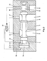
- Fig. 2 also shows a so-called "pressure differential balance" with cylinder housing 1, balance piston 2, pump pressure channel 3, pump pressure side 5, control edge 6, tank drain 7, load pressure side 8, consumer pressure channel (load pressure channel) 9, spring 10.
- This pressure differential balance can also in a hydraulic circuit can be included, as shown with the pump 26, valve 27 and consumer 28 in Fig. 1.
- the balance piston 2 has the same functions as discussed in FIG. 1.
- the connection between pump pressure channel 3 and pump pressure side 5 of the pressure differential balance is made through the overflow channel 29, in which the valve 30 is switched on.
- a holding piston 31 is provided in a holding cylinder 32.
- the holding piston has a plunger 33, which supports the balance piston 2 on the pump pressure side 5 ′.
- the piston area of the holding piston 31 on the working side 34 of the holding piston is substantially larger than the piston area of the balance piston on the pump pressure side 5.
- the holding cylinder 32 and pump pressure chamber 5 of the pressure differential balance 2 merge into one another. However, it is also possible that both are sealed against one another on the tappet 33.
- the valve 30 is provided for switching the functions of the holding piston 31 and the balance piston 2.
- the valve 30 is a two-position valve.
- the pump pressure channel 3 is connected to the working side 34 of the holding piston 31 via channel 37 and channel 38, and the pump pressure side 5 is connected to the tank discharge channel 7 via channel 29 and channel 36.
- the working side 34 of the holding piston 31 is acted on by the pump pressure.
- an increased force is therefore opposed to the spring 10, so that the balance piston 2 extends further to the right when idling and thus releases a larger flow at the control edge 6 between the pump and the tank. This can result in a low residual pump pressure.
- valve 30 If there is a consumer pressure on the consumer pressure side 8 of the differential pressure balance, i.e. In the operating positions of valve 27 according to FIG. 1, this consumer pressure via channel 35 is used to actuate valve 30. The valve 30 then releases a connection of the pump pressure channel 3 via channel 37 and channel 29 to the pump pressure side 5 of the balance piston 2 and on the other hand connects the working side 34 of the holding piston 31 via channel 38 to the tank drain 7. This means that when the pressure differential is applied to the load differential Holding piston 31 is moved away to the left and is deactivated.
Landscapes
- Engineering & Computer Science (AREA)
- Physics & Mathematics (AREA)
- Fluid Mechanics (AREA)
- Mechanical Engineering (AREA)
- General Engineering & Computer Science (AREA)
- Fluid-Pressure Circuits (AREA)
- Control Of Positive-Displacement Pumps (AREA)
- Safety Valves (AREA)
Applications Claiming Priority (2)
| Application Number | Priority Date | Filing Date | Title |
|---|---|---|---|
| DE2908018 | 1979-03-01 | ||
| DE19792908018 DE2908018A1 (de) | 1979-03-01 | 1979-03-01 | Hydraulische steuervorrichtung fuer lastunabhaengige durchflussregelung |
Publications (3)
| Publication Number | Publication Date |
|---|---|
| EP0015492A2 true EP0015492A2 (fr) | 1980-09-17 |
| EP0015492A3 EP0015492A3 (en) | 1981-02-18 |
| EP0015492B1 EP0015492B1 (fr) | 1984-01-04 |
Family
ID=6064215
Family Applications (1)
| Application Number | Title | Priority Date | Filing Date |
|---|---|---|---|
| EP80100962A Expired EP0015492B1 (fr) | 1979-03-01 | 1980-02-27 | Dispositif de commande hydraulique indépendant de la charge pour la régulation du débit |
Country Status (3)
| Country | Link |
|---|---|
| US (2) | US4303091A (fr) |
| EP (1) | EP0015492B1 (fr) |
| DE (1) | DE2908018A1 (fr) |
Families Citing this family (17)
| Publication number | Priority date | Publication date | Assignee | Title |
|---|---|---|---|---|
| DE3146322A1 (de) * | 1981-11-23 | 1983-06-01 | Danfoss A/S, 6430 Nordborg | Steuerventileinrichtung fuer einen hydraulischen verbraucher |
| US4693272A (en) * | 1984-02-13 | 1987-09-15 | Husco International, Inc. | Post pressure compensated unitary hydraulic valve |
| JPS60147574U (ja) * | 1984-03-13 | 1985-10-01 | 自動車機器株式会社 | 動力舵取装置 |
| US4663936A (en) * | 1984-06-07 | 1987-05-12 | Eaton Corporation | Load sensing priority system with bypass control |
| DE3690051C1 (de) * | 1985-02-23 | 1997-09-18 | Barmag Barmer Maschf | Proportionalventil mit einem einstellbaren Drosselventil zwischen Pumpe und Last sowie einer Druckwaage |
| US4738104A (en) * | 1985-03-23 | 1988-04-19 | Barmag Ag | Hydraulic power system |
| DE3521579A1 (de) * | 1985-06-15 | 1986-12-18 | J.M. Voith Gmbh, 7920 Heidenheim | Steuerventil |
| DE3625222A1 (de) * | 1986-07-25 | 1988-02-04 | Index Werke Kg Hahn & Tessky | Druckregler fuer hydraulisch gesteuerte werkzeugmaschinen |
| US4798126A (en) * | 1987-03-23 | 1989-01-17 | Caterpillar Inc. | Load responsive system using load responsive pump control of a bypass type |
| IT1213973B (it) * | 1987-07-17 | 1990-01-05 | Oleostar Srl | Valvola di controllo del flusso per circuito idraulico prioritario di potenza |
| DE4421357A1 (de) * | 1994-06-18 | 1995-12-21 | Bosch Gmbh Robert | Pneumatisches Wegeventil |
| KR100208732B1 (ko) * | 1996-05-21 | 1999-07-15 | 토니헬샴 | 가변 재생기능이 구비된 중장비용 콘트롤밸브 |
| DE19725472A1 (de) * | 1997-06-17 | 1998-12-24 | Bosch Gmbh Robert | Mengenregelventil |
| US10007276B2 (en) * | 2014-05-20 | 2018-06-26 | Hamilton Sundstrand Corporation | Pressure-regulating valves |
| US9791062B2 (en) | 2014-10-13 | 2017-10-17 | Fema Corporation Of Michigan | Hydraulic valve having pressure compensated flow control |
| CN110477999B (zh) * | 2019-08-29 | 2021-07-02 | 湖南瀚德微创医疗科技有限公司 | 一种输出恒定夹持力的手术夹钳 |
| CN113108102B (zh) * | 2021-03-30 | 2023-02-03 | 中国船舶重工集团公司第七0四研究所 | 一种用于提高大型海工波浪补偿装置安全性的限速切断阀 |
Family Cites Families (8)
| Publication number | Priority date | Publication date | Assignee | Title |
|---|---|---|---|---|
| CH444601A (de) * | 1966-12-13 | 1967-09-30 | Beringer Hydraulik Gmbh | Steuervorrichtung für hydraulisch betriebene Einrichtungen |
| US3631890A (en) * | 1970-04-06 | 1972-01-04 | Borg Warner | Flow extending bypass valve |
| CH534816A (de) * | 1972-02-18 | 1973-03-15 | Beringer Hydraulik Gmbh | Steuervorrichtung für lastunabhängige Durchflussregelung |
| US3777773A (en) * | 1972-02-22 | 1973-12-11 | Koehring Co | Pressure compensating valve mechanism |
| US4178962A (en) * | 1972-10-30 | 1979-12-18 | Tomco, Inc. | Control valve with flow control means |
| DE2320935B1 (de) * | 1973-04-25 | 1974-06-12 | Heilmeier & Weinlein, Fabrik Fuer Oel-Hydraulik, 8000 Muenchen | Leerlaufventil |
| US3971216A (en) * | 1974-06-19 | 1976-07-27 | The Scott & Fetzer Company | Load responsive system with synthetic signal |
| US3937129A (en) * | 1974-10-23 | 1976-02-10 | The Scott & Fetzer Company | Load responsive system with area change flow extender |
-
1979
- 1979-03-01 DE DE19792908018 patent/DE2908018A1/de not_active Withdrawn
-
1980
- 1980-02-27 US US06/125,096 patent/US4303091A/en not_active Expired - Lifetime
- 1980-02-27 EP EP80100962A patent/EP0015492B1/fr not_active Expired
-
1981
- 1981-09-23 US US06/304,716 patent/US4355655A/en not_active Expired - Fee Related
Also Published As
| Publication number | Publication date |
|---|---|
| US4303091A (en) | 1981-12-01 |
| EP0015492B1 (fr) | 1984-01-04 |
| US4355655A (en) | 1982-10-26 |
| EP0015492A3 (en) | 1981-02-18 |
| DE2908018A1 (de) | 1980-09-11 |
Similar Documents
| Publication | Publication Date | Title |
|---|---|---|
| DE19853355C1 (de) | Hydraulisch steuerbares Hubventil | |
| DE3323363C2 (fr) | ||
| DE69525896T2 (de) | Dämpfer | |
| EP0015492B1 (fr) | Dispositif de commande hydraulique indépendant de la charge pour la régulation du débit | |
| DE10021793A1 (de) | Einrichtung zur Ansteuerung von CVT-Getrieben | |
| DE102012208307A1 (de) | Dämpfungsvorrichtung | |
| EP0103250B1 (fr) | Soupape de contrôle pour contrôle hydraulique | |
| DE1917488C3 (fr) | ||
| DE2735559A1 (de) | Steuergeraet fuer hydraulische arbeitsgeraete | |
| DE4036564A1 (de) | Hydraulische einrichtung zur steuerung eines arbeitszylinders einer presse | |
| DE69206170T2 (de) | Proportionales Wegeventil und Steuersystem für mehrere hydraulische Verbrauchen, wobei jeder solch ein Ventil beinhaltet. | |
| DE1917488B2 (de) | Steuereinrichtung fuer eine hydromaschine | |
| DE3420990A1 (de) | Hydraulikanlage | |
| EP0600918B1 (fr) | Dispositif de reglage hydraulique | |
| DE3688346T2 (de) | Hydraulisches steuersystem. | |
| DE2336512C2 (de) | Ventil | |
| LU84377A1 (de) | Einstellbares drosselventil | |
| DE102004054108B4 (de) | Dreiwegeventil und dieses aufweisende Brennstoffeinspritzvorrichtung | |
| DE2112382A1 (de) | Hydraulische Maschine mit veraenderlicher Verdraengung | |
| DE69302443T2 (de) | Steuervorrichtung für mehrere hydraulische Verbraucher | |
| DE3039002C2 (de) | Druckregelventil | |
| DE2537957A1 (de) | Steuer- bzw. regelanordnung fuer pumpen mit variabler verdraengung | |
| EP1144885B1 (fr) | Systeme de commande hydraulique pour une transmission a variation continue | |
| EP1369596B1 (fr) | Agencement de distributeur hydraulique | |
| EP0375916B1 (fr) | Distributeur pour commander un cylindre hydraulique |
Legal Events
| Date | Code | Title | Description |
|---|---|---|---|
| PUAI | Public reference made under article 153(3) epc to a published international application that has entered the european phase |
Free format text: ORIGINAL CODE: 0009012 |
|
| AK | Designated contracting states |
Designated state(s): CH FR GB NL SE |
|
| PUAL | Search report despatched |
Free format text: ORIGINAL CODE: 0009013 |
|
| AK | Designated contracting states |
Designated state(s): CH FR GB NL SE |
|
| 17P | Request for examination filed |
Effective date: 19810523 |
|
| GRAA | (expected) grant |
Free format text: ORIGINAL CODE: 0009210 |
|
| AK | Designated contracting states |
Designated state(s): CH FR GB NL SE |
|
| PG25 | Lapsed in a contracting state [announced via postgrant information from national office to epo] |
Ref country code: SE Effective date: 19840104 Ref country code: NL Effective date: 19840104 |
|
| PGFP | Annual fee paid to national office [announced via postgrant information from national office to epo] |
Ref country code: CH Payment date: 19840206 Year of fee payment: 5 |
|
| NLV1 | Nl: lapsed or annulled due to failure to fulfill the requirements of art. 29p and 29m of the patents act | ||
| EN | Fr: translation not filed | ||
| PLBI | Opposition filed |
Free format text: ORIGINAL CODE: 0009260 |
|
| 26 | Opposition filed |
Opponent name: MANNESMANN REXROTH GMBH Effective date: 19840920 |
|
| PG25 | Lapsed in a contracting state [announced via postgrant information from national office to epo] |
Ref country code: GB Effective date: 19860227 |
|
| RDAG | Patent revoked |
Free format text: ORIGINAL CODE: 0009271 |
|
| STAA | Information on the status of an ep patent application or granted ep patent |
Free format text: STATUS: PATENT REVOKED |
|
| 27W | Patent revoked |
Effective date: 19860307 |
|
| REG | Reference to a national code |
Ref country code: CH Ref legal event code: PL |
|
| GBPC | Gb: european patent ceased through non-payment of renewal fee | ||
| GBPR | Gb: patent revoked under art. 102 of the ep convention designating the uk as contracting state |