EP0015529B1 - Appareil d'étiquetage - Google Patents
Appareil d'étiquetage Download PDFInfo
- Publication number
- EP0015529B1 EP0015529B1 EP80101053A EP80101053A EP0015529B1 EP 0015529 B1 EP0015529 B1 EP 0015529B1 EP 80101053 A EP80101053 A EP 80101053A EP 80101053 A EP80101053 A EP 80101053A EP 0015529 B1 EP0015529 B1 EP 0015529B1
- Authority
- EP
- European Patent Office
- Prior art keywords
- ribbon
- roll
- clamping device
- label
- take
- Prior art date
- Legal status (The legal status is an assumption and is not a legal conclusion. Google has not performed a legal analysis and makes no representation as to the accuracy of the status listed.)
- Expired
Links
- 238000002372 labelling Methods 0.000 title claims abstract description 25
- 239000000853 adhesive Substances 0.000 claims abstract description 15
- 230000033001 locomotion Effects 0.000 claims description 11
- 238000004804 winding Methods 0.000 claims description 8
- 230000005540 biological transmission Effects 0.000 claims description 5
- 230000008878 coupling Effects 0.000 claims description 2
- 238000010168 coupling process Methods 0.000 claims description 2
- 238000005859 coupling reaction Methods 0.000 claims description 2
- 230000004888 barrier function Effects 0.000 description 12
- 238000000034 method Methods 0.000 description 5
- 230000001960 triggered effect Effects 0.000 description 5
- 238000003825 pressing Methods 0.000 description 4
- 230000007257 malfunction Effects 0.000 description 3
- 230000001070 adhesive effect Effects 0.000 description 2
- 238000004519 manufacturing process Methods 0.000 description 2
- 230000001154 acute effect Effects 0.000 description 1
- 235000013405 beer Nutrition 0.000 description 1
- 210000000078 claw Anatomy 0.000 description 1
- 230000000694 effects Effects 0.000 description 1
- 239000013013 elastic material Substances 0.000 description 1
- 239000002360 explosive Substances 0.000 description 1
- 229920001821 foam rubber Polymers 0.000 description 1
- 238000012423 maintenance Methods 0.000 description 1
- 210000000056 organ Anatomy 0.000 description 1
Images

Classifications
-
- B—PERFORMING OPERATIONS; TRANSPORTING
- B65—CONVEYING; PACKING; STORING; HANDLING THIN OR FILAMENTARY MATERIAL
- B65C—LABELLING OR TAGGING MACHINES, APPARATUS, OR PROCESSES
- B65C9/00—Details of labelling machines or apparatus
- B65C9/40—Controls; Safety devices
- B65C9/42—Label feed control
- B65C9/44—Label feed control by special means responsive to marks on labels or articles
-
- B—PERFORMING OPERATIONS; TRANSPORTING
- B65—CONVEYING; PACKING; STORING; HANDLING THIN OR FILAMENTARY MATERIAL
- B65C—LABELLING OR TAGGING MACHINES, APPARATUS, OR PROCESSES
- B65C9/00—Details of labelling machines or apparatus
- B65C9/08—Label feeding
- B65C9/18—Label feeding from strips, e.g. from rolls
- B65C9/1865—Label feeding from strips, e.g. from rolls the labels adhering on a backing strip
- B65C9/1876—Label feeding from strips, e.g. from rolls the labels adhering on a backing strip and being transferred by suction means
- B65C9/1884—Label feeding from strips, e.g. from rolls the labels adhering on a backing strip and being transferred by suction means the suction means being a movable vacuum arm or pad
-
- Y—GENERAL TAGGING OF NEW TECHNOLOGICAL DEVELOPMENTS; GENERAL TAGGING OF CROSS-SECTIONAL TECHNOLOGIES SPANNING OVER SEVERAL SECTIONS OF THE IPC; TECHNICAL SUBJECTS COVERED BY FORMER USPC CROSS-REFERENCE ART COLLECTIONS [XRACs] AND DIGESTS
- Y10—TECHNICAL SUBJECTS COVERED BY FORMER USPC
- Y10T—TECHNICAL SUBJECTS COVERED BY FORMER US CLASSIFICATION
- Y10T156/00—Adhesive bonding and miscellaneous chemical manufacture
- Y10T156/17—Surface bonding means and/or assemblymeans with work feeding or handling means
- Y10T156/1702—For plural parts or plural areas of single part
- Y10T156/1705—Lamina transferred to base from adhered flexible web or sheet type carrier
- Y10T156/1707—Discrete spaced laminae on adhered carrier
- Y10T156/171—Means serially presenting discrete base articles or separate portions of a single article
Definitions
- the invention relates to a labeling device of the type specified in the preamble of claim 1.
- a labeling device of this type is known (DE-A1-2 516 195), which operates fully pneumatically and which is primarily intended for automatic operation in potentially explosive areas.
- the tape is fed there by means of preferred rollers pressing against each other and against the label tape, which can be driven by a pneumatic motor.
- the preferred mechanism is controlled by an air barrier that responds to control holes located in the label tape.
- the automatic operation of such a labeling device always leads to malfunctions, because the air barrier z. B. does not respond due to missing or clogged control holes in the label tape. This can lead to multiple labeling or label jams, which can make it necessary to switch off the labeling device and the conveyor system for the objects to be labeled.
- both for the preferred mechanism as well as for a possible tape rewinder under constant alternating stress gear motors are provided, which require frequent maintenance because of a prone to wear, especially during continuous operation.
- the pull-off roller braked by a friction member is driven by the pulling-off label tape, while the take-up roller for the empty label tape can be driven by means of a motor provided specifically for this purpose.
- a stationary belt clamping device which can be actuated in opposition to the latter is arranged and which is intended to prevent tape withdrawal from the take-up reel when the movable belt clamping device is moved back.
- the invention has for its object to improve the known labeling device of the type specified in the preamble of claim 1 with respect to its drive and control mechanism in such a way that reliable, fully automatic operation is ensured even if individual control markings fail.
- the preferred mechanism according to the invention with its linearly displaceable tape clamping device by means of which the label preference can be controlled both via the scanning device and also via the redundant switching element, which is preferably designed as a mechanical limit switch valve, also ensures trouble-free operation if there are occasionally missing control markings in the label tape.
- the tape tensioning mechanism acting on the take-up reel and the backstop enable the tape clamping device to be reliably pushed back without the label tape which may be adhering being unwantedly taken back again.
- the tape tension required for reliable operation is obtained according to a preferred embodiment of the invention in that the take-up roll is connected via a transmission gear containing a slip clutch to the take-off roll which can be driven by the pulling-off label tape essentially without slippage.
- the translation of the transmission gear corresponds at least to the ratio between the diameters of the empty take-up roll and the full take-up roll.
- the transmission gear can be designed as a belt drive, chain gear or gear transmission, while the slip clutch can be formed by a slip hub coupling the pull-off roller with the associated belt or driven pulley.
- a freewheel is preferably provided as a backstop on the side of the winding roll.
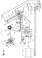
- the labeling systems shown schematically in the drawing essentially consist of a labeling device 6 arranged above a conveyor track 2 for the transport of the items 4 to be labeled, in which label tape 12 carrying a self-adhesive label 10 carries a self-adhesive label 10 from a supply and take-off roll 14 with the aid of a pneumatically operating preferred mechanism 8 withdrawn, past a pneumatically actuated printing unit 16, a scanning device 18, a dispensing edge 20 and a pneumatically actuated pressing mechanism 22 and is wound up on a take-up reel 23.
- the labeling process including tape advance and printing process, is triggered via a trigger mechanism 24 which is mechanically actuated by the objects to be labeled and which is arranged in the region of the conveyor track 2.
- the objects to be labeled are beer kegs 4, which are transported upright on a roller conveyor 2 and which are to be labeled on their lid as precisely as possible next to the bunghole.
- the label tape 12 coming from the take-off roller 14 passes via a deflection roller 26 and through the printing station 16 to the scanning device 18, which consists of an air barrier in which a transmitter nozzle 28 and a receiver nozzle 30 are arranged opposite one another on a fork-shaped part.
- the label tape 12 has holes 32 at the label spacing, as shown in FIG. 3.
- the label tape is preferred step by step, the step size normally being controlled via the scanning device 18 by scanning the holes 32.
- the label tape 12 with self-adhesive labels 10 pointing upward arrives at the sharp-edged dispensing edge 20, at which it is deflected such that the self-adhesive label 10 ′ previously arranged on the label tape 12 is detached from the base and a little further the dispensing edge 20 is pushed forward while the empty label band 12 'is pulled down at an acute angle.
- the self-adhesive label 10 'released is sucked in via suction air openings in the free lower surface of the stamp 40 of the pressing mechanism 22 and held there by the suction effect.
- the punch 40 is arranged at the end of a piston rod 42 of a relatively long pneumatic cylinder 44.
- the preferred mechanism 8 contains a pneumatic tape clamping device 50 which can be moved back and forth by means of a pneumatic cylinder 46 in the direction of the double arrow 48 and which is actuated in such a way that, during the forward movement, it holds the empty label tape 12 'by pressing the clamping claw 52 and takes it with it while moving it back is open.
- the preferred path of the label tape 12 is normally controlled by the scanning device 18, which emits a signal to open the tape clamp device 50 in the presence of a hole 32 in the label tape 12.
- the scanning device 18 which emits a signal to open the tape clamp device 50 in the presence of a hole 32 in the label tape 12.
- a redundant pneumatic limit switch valve 54 is additionally provided, which can be mechanically actuated directly by the belt clamping device 50 and which reverses the belt clamping device 50 after an adjustable feed path has been reached.
- the output signals of the limit switching valve 54 and the scanning device 18 are linked to one another via an OR logic 56.
- a stationary tape clamping device 58 which can be actuated in opposition to this and which should ensure that the empty label tape 12 'reaches the winding roller 23 when it is pulled forward and when the movable tape is moved back Band clamping device 50 is not inadvertently taken back by it.
- the symbols S and O identify the inputs for the closing or opening of the two belt clamping devices 50 and 58 and the two centering barriers 70 explained below.
- traces of adhesive are inevitably transferred from the empty label tape 12 'to the clamping jaws of the tape clamping devices 50, 58, which gradually accumulate there and cause sticking phenomena between the clamping jaws and guide the empty label tape 12 '.
- the movable tape clamping device 50 can tear away from the possibly adhering empty label tape 12 'under its own power when moving back, this is not readily the case with the stationary tape clamping device 58, so that it is there during tape feed due to the slackness of the empty label tape 12'. can easily lead to a belt jam and thus serious operational disruptions.
- the stationary tape clamping device 58 is omitted in the labeling device shown in FIG. 1a.
- a backstop 82, 83 is provided on the take-up roll 23, which ensures that the empty label tape 12 'wound on the take-up roll 23 cannot be pulled off again.
- the backstop is indicated as a spring-loaded pawl 83 which engages in a circumferential toothing 82 of the winding roller 23. It is more appropriate to use a freewheel, not shown, as a backstop, which enables a continuous winding.
- FIGS. 1 and 1 Another difference between the exemplary embodiments shown in FIGS. 1 and 1 lies in the type of reversal of the movable belt clamping device 50: While in the case of FIG. 1, the reversal of the direction of movement simultaneously with the opening of the belt clamping device 50 via the output signal of the OR gate 56 In the case of FIG. 1 a, the direction of movement is reversed solely via the output signal of the limit switch valve 54, after the tape clamping device 50 has normally been opened shortly beforehand via the scanning device 18 by actuation via the OR gate 56 and the tape advance has thus been interrupted . With the latter arrangement, a reliable switching sequence is obtained during the reversal. In both cases, the feed path of the movable tape clamping device 50 to the limit switching valve 54 is to be set slightly larger than the label spacing on the label tape 12.
- the take-off roller 14 is driven in a largely slip-free manner in the direction of the arrow 60 via the label tape 12 drawn off by the preferred mechanism 8. It is coupled to the pulley 64 via a slide hub (not shown), which in turn is connected via a belt drive 63 to the pulley 66 of the winding roller 23 in such a way that the winding roller 23 is driven in the direction of arrow 62.
- the ratio defined by the different diameters of the pulleys 64 and 66 is selected so that the empty take-up roll 23 is driven at full angular speed when the take-up roll 14 is full.
- the aforementioned slip hub ensures that a certain band tension is constantly maintained during winding.
- the labeling process is triggered by two switching valves of the trigger mechanism 24, identified by the symbols A and B, which are activated by means of two levers 72A, which engage laterally in the roller track 2, are linked to centering barriers 70 and arrive by means of a barrel 4 which can be pivoted against the centering barriers by the driven roller track 2.
- 72B can be operated.
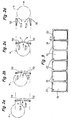
- the AND gate 74 causes the labeling process to be triggered only when both switching valves A, B are actuated simultaneously, which means that the barrel 4 is correctly centered (see FIGS. 2a-2c).
- the stamp 40 is first moved obliquely downward by displacing the piston rod 42 until it strikes the drum cover with its lower surface carrying the self-adhesive label 10 '.
- the plunger 40 is articulated on a transverse axis of the piston rod 42 and is connected to it via a plurality of independently compressible or expandable coil springs 41 and consists in its lower part of an elastic material, for example made of foam rubber.
- a pressure switching valve 76 which is acted upon by the internal pressure of the pneumatic cylinder 44, the stamp 40 is pulled back into its starting position, while the self-adhesive label 10 'remains adhering to the barrel lid.
- the plunger 40 actuates a switching valve 78 via an organ connected thereto, via which both the centering barriers 70 and the pneumatic cylinder 46 and the belt clamping device 50 of the preferred mechanism 8 and, in the case of FIG. 1, the belt clamping device 58 are controlled.
- the labeled drum 4 is released for further transport by opening the centering barriers 70 (see FIG. 2d).
- the renewed closing of the centering barriers 70 is triggered by a light barrier 80 which emits a signal when the labeled barrel 4 has left the area of the centering barriers 70.
- the label tape 12 is pulled forward by a hole spacing while detaching a new self-adhesive label 10 'for the stamp 40.
- the self-adhesive label 10 that has come under the printing unit 16 is then printed.
- the system is then ready for a further labeling process which is triggered by the next drum 4.
Landscapes
- Labeling Devices (AREA)
Claims (10)
Priority Applications (1)
| Application Number | Priority Date | Filing Date | Title |
|---|---|---|---|
| AT80101053T ATE284T1 (de) | 1979-03-12 | 1980-03-03 | Etikettiervorrichtung. |
Applications Claiming Priority (2)
| Application Number | Priority Date | Filing Date | Title |
|---|---|---|---|
| DE19792909655 DE2909655A1 (de) | 1977-05-04 | 1979-03-12 | Etikettiervorrichtung |
| DE2909655 | 1979-03-12 |
Publications (2)
| Publication Number | Publication Date |
|---|---|
| EP0015529A1 EP0015529A1 (fr) | 1980-09-17 |
| EP0015529B1 true EP0015529B1 (fr) | 1981-10-14 |
Family
ID=6065153
Family Applications (1)
| Application Number | Title | Priority Date | Filing Date |
|---|---|---|---|
| EP80101053A Expired EP0015529B1 (fr) | 1979-03-12 | 1980-03-03 | Appareil d'étiquetage |
Country Status (4)
| Country | Link |
|---|---|
| US (1) | US4270968A (fr) |
| EP (1) | EP0015529B1 (fr) |
| AT (1) | ATE284T1 (fr) |
| DE (1) | DE3060034D1 (fr) |
Families Citing this family (14)
| Publication number | Priority date | Publication date | Assignee | Title |
|---|---|---|---|---|
| US4427484A (en) | 1982-07-29 | 1984-01-24 | Camtron Systems, Inc. | Automatic labeling system |
| JPS5974040A (ja) * | 1982-10-08 | 1984-04-26 | 大日本印刷株式会社 | ラベル貼付方法及び装置 |
| US4869775A (en) * | 1988-04-26 | 1989-09-26 | Quittner John P | Tab depositing dispenser |
| US5370754A (en) * | 1991-06-27 | 1994-12-06 | Pfizer Inc. | Automatic motorless label applying system |
| US5188696A (en) * | 1991-07-31 | 1993-02-23 | Good Jr Kenneth W | Wrap around labeling machine |
| US5232540A (en) * | 1991-09-30 | 1993-08-03 | Ithaca Industries, Inc. | Automatic labeling machine and method |
| US5304264A (en) * | 1991-11-05 | 1994-04-19 | Automated Packaging Systems, Inc. | Item applicator and method |
| US5277741A (en) * | 1992-08-06 | 1994-01-11 | Bartlett Tool And Manufacturing, Inc. | Sealing apparatus |
| US5466328A (en) * | 1992-08-31 | 1995-11-14 | Fuji Xerox Co., Ltd. | Recorded sheet processing unit for image forming apparatus |
| JP2540824Y2 (ja) * | 1992-10-08 | 1997-07-09 | 株式会社サトー | ラベル貼付機のラベルピッチ切替装置 |
| DE9407305U1 (de) * | 1994-05-02 | 1994-09-22 | Czewo Plast Kunststofftechnik Gmbh, 93073 Neutraubling | Vorrichtung zur Abgabe von Auftrags-Material |
| US5849143A (en) * | 1997-04-18 | 1998-12-15 | Booth Manufacturing Company | Precision label application |
| US7328543B2 (en) * | 2006-05-17 | 2008-02-12 | Plitek, L.L.C. | Apparatus and method for the application of pressure relief valves |
| TWI557030B (zh) * | 2014-07-30 | 2016-11-11 | 迅智自動化科技股份有限公司 | 標籤機 |
Family Cites Families (6)
| Publication number | Priority date | Publication date | Assignee | Title |
|---|---|---|---|---|
| US2920780A (en) * | 1956-10-01 | 1960-01-12 | Western Electric Co | Apparatus for applying pressure sensitive adhesive labels to articles |
| US3779829A (en) * | 1972-01-24 | 1973-12-18 | Njm Inc | Labeling machine |
| US3953278A (en) * | 1974-11-04 | 1976-04-27 | J. P. Stevens & Co., Inc. | Sticker applicator |
| US4019935A (en) * | 1975-05-14 | 1977-04-26 | Diamond International Corporation | Automatic feeding of labels for application to bottles or other containers |
| DE2719957C3 (de) * | 1977-05-04 | 1982-02-11 | Etifix Gebr. Dudzik, 7441 Neckartailfingen | Etikettiervorrichtung |
| US4188252A (en) * | 1977-08-31 | 1980-02-12 | Automecha Ltd. | Label positioning and applying apparatus |
-
1980
- 1980-03-03 AT AT80101053T patent/ATE284T1/de not_active IP Right Cessation
- 1980-03-03 EP EP80101053A patent/EP0015529B1/fr not_active Expired
- 1980-03-03 DE DE8080101053T patent/DE3060034D1/de not_active Expired
- 1980-06-02 US US06/127,313 patent/US4270968A/en not_active Expired - Lifetime
Also Published As
| Publication number | Publication date |
|---|---|
| ATE284T1 (de) | 1981-10-15 |
| EP0015529A1 (fr) | 1980-09-17 |
| US4270968A (en) | 1981-06-02 |
| DE3060034D1 (en) | 1981-12-24 |
Similar Documents
| Publication | Publication Date | Title |
|---|---|---|
| EP0015529B1 (fr) | Appareil d'étiquetage | |
| DE2427324C2 (de) | Maschine zum wahlweisen Verarbeiten von Artikelkarten | |
| JPH07501014A (ja) | 固定用ツール及びそのためのテープ | |
| DE2809360C3 (de) | Verfahren und Vorrichtung zum Wickeln und Kassettieren eines Filmbandes | |
| DE1910157B2 (fr) | ||
| DE2710605C2 (de) | Etikettiermaschine | |
| DE102011108178A1 (de) | Foliendrucksystem und Verfahren zum positionsgenauen Bedrucken einer Kunststofffolie | |
| DE2223557C2 (de) | Verfahren zum Aufbringen von Aufklebern auf eine Endlosbahn | |
| DE102012223290A1 (de) | Vorrichtung und Verfahren zum Banderolieren von Stapeln | |
| DE3618542C2 (fr) | ||
| DE3215288C2 (fr) | ||
| DE2410332A1 (de) | Vorrichtung zum verschliessen von beuteln, schlaeuchen und aehnlichem folienartigen material | |
| EP0006179A1 (fr) | Mécanisme d'avance d'une bande de support pour étiquettes | |
| DE2217032C3 (de) | Vorrichtung zum Anbringen von aus einer fortlaufenden Bahn hergestellten Zuschnitten an Gegenständen | |
| DE2719957C3 (de) | Etikettiervorrichtung | |
| DE3310839C2 (fr) | ||
| DE2909655A1 (de) | Etikettiervorrichtung | |
| DE2858372C2 (fr) | ||
| DE2837164A1 (de) | Umreifungsmaschine fuer das umreifen von packguetern | |
| DE4132369A1 (de) | Vorrichtung zum bedrucken und ausgeben von auf einem traegermaterialstreifen haftenden etiketten | |
| DE3049248C2 (de) | Etikettiervorrichtung | |
| EP0123097A1 (fr) | Procédé pour l'étiquetage semi-automatique ou automatique d'articles ainsi que le dispositif d'étiquetage pour la réalisation de ce procédé | |
| US3626657A (en) | Tying mechanism for bails and the like | |
| DE1923994B1 (de) | Vorrichtung zum taktweisen Vorschub eines in Abstaenden mit abloesbaren Selbstklebeetiketten besetzten Traegerbandes | |
| DE3818793A1 (de) | Vorrichtung zum ausrichten und oeffnen flachliegender kunststoffsaecke |
Legal Events
| Date | Code | Title | Description |
|---|---|---|---|
| PUAI | Public reference made under article 153(3) epc to a published international application that has entered the european phase |
Free format text: ORIGINAL CODE: 0009012 |
|
| AK | Designated contracting states |
Designated state(s): AT BE CH DE FR GB IT NL SE |
|
| 17P | Request for examination filed | ||
| ITF | It: translation for a ep patent filed | ||
| GRAA | (expected) grant |
Free format text: ORIGINAL CODE: 0009210 |
|
| AK | Designated contracting states |
Designated state(s): AT BE CH DE FR GB IT NL SE |
|
| REF | Corresponds to: |
Ref document number: 284 Country of ref document: AT Date of ref document: 19811015 Kind code of ref document: T |
|
| REF | Corresponds to: |
Ref document number: 3060034 Country of ref document: DE Date of ref document: 19811224 |
|
| ITTA | It: last paid annual fee | ||
| EAL | Se: european patent in force in sweden |
Ref document number: 80101053.9 |
|
| PGFP | Annual fee paid to national office [announced via postgrant information from national office to epo] |
Ref country code: DE Payment date: 19950325 Year of fee payment: 16 |
|
| PGFP | Annual fee paid to national office [announced via postgrant information from national office to epo] |
Ref country code: NL Payment date: 19950331 Year of fee payment: 16 |
|
| PGFP | Annual fee paid to national office [announced via postgrant information from national office to epo] |
Ref country code: FR Payment date: 19950410 Year of fee payment: 16 |
|
| PGFP | Annual fee paid to national office [announced via postgrant information from national office to epo] |
Ref country code: GB Payment date: 19950413 Year of fee payment: 16 |
|
| PGFP | Annual fee paid to national office [announced via postgrant information from national office to epo] |
Ref country code: AT Payment date: 19950414 Year of fee payment: 16 |
|
| PGFP | Annual fee paid to national office [announced via postgrant information from national office to epo] |
Ref country code: SE Payment date: 19950418 Year of fee payment: 16 |
|
| PGFP | Annual fee paid to national office [announced via postgrant information from national office to epo] |
Ref country code: CH Payment date: 19950421 Year of fee payment: 16 |
|
| PGFP | Annual fee paid to national office [announced via postgrant information from national office to epo] |
Ref country code: BE Payment date: 19950428 Year of fee payment: 16 |
|
| PG25 | Lapsed in a contracting state [announced via postgrant information from national office to epo] |
Ref country code: GB Effective date: 19960303 Ref country code: AT Effective date: 19960303 |
|
| PG25 | Lapsed in a contracting state [announced via postgrant information from national office to epo] |
Ref country code: SE Effective date: 19960304 |
|
| PG25 | Lapsed in a contracting state [announced via postgrant information from national office to epo] |
Ref country code: CH Effective date: 19960331 Ref country code: BE Effective date: 19960331 |
|
| BERE | Be: lapsed |
Owner name: J. U. W. DUDZIK 0HG Effective date: 19960331 |
|
| PG25 | Lapsed in a contracting state [announced via postgrant information from national office to epo] |
Ref country code: NL Effective date: 19961001 |
|
| GBPC | Gb: european patent ceased through non-payment of renewal fee |
Effective date: 19960303 |
|
| REG | Reference to a national code |
Ref country code: CH Ref legal event code: PL |
|
| PG25 | Lapsed in a contracting state [announced via postgrant information from national office to epo] |
Ref country code: FR Effective date: 19961129 |
|
| NLV4 | Nl: lapsed or anulled due to non-payment of the annual fee |
Effective date: 19961001 |
|
| PG25 | Lapsed in a contracting state [announced via postgrant information from national office to epo] |
Ref country code: DE Effective date: 19961203 |
|
| EUG | Se: european patent has lapsed |
Ref document number: 80101053.9 |
|
| REG | Reference to a national code |
Ref country code: FR Ref legal event code: ST |
|
| PLBE | No opposition filed within time limit |
Free format text: ORIGINAL CODE: 0009261 |
|
| STAA | Information on the status of an ep patent application or granted ep patent |
Free format text: STATUS: NO OPPOSITION FILED WITHIN TIME LIMIT |