EP0015530B1 - Verfahren und Vorrichtung zur automatischen Wasserdosierung zum Betreiben einer Giessereikühltrommel für das gleichzeitige Kühlen von Form- und Kernsand und Guss - Google Patents
Verfahren und Vorrichtung zur automatischen Wasserdosierung zum Betreiben einer Giessereikühltrommel für das gleichzeitige Kühlen von Form- und Kernsand und Guss Download PDFInfo
- Publication number
- EP0015530B1 EP0015530B1 EP80101056A EP80101056A EP0015530B1 EP 0015530 B1 EP0015530 B1 EP 0015530B1 EP 80101056 A EP80101056 A EP 80101056A EP 80101056 A EP80101056 A EP 80101056A EP 0015530 B1 EP0015530 B1 EP 0015530B1
- Authority
- EP
- European Patent Office
- Prior art keywords
- water
- cooling drum
- sand
- cooling
- temperature
- Prior art date
- Legal status (The legal status is an assumption and is not a legal conclusion. Google has not performed a legal analysis and makes no representation as to the accuracy of the status listed.)
- Expired
Links
- 238000001816 cooling Methods 0.000 title claims abstract description 57
- XLYOFNOQVPJJNP-UHFFFAOYSA-N water Substances O XLYOFNOQVPJJNP-UHFFFAOYSA-N 0.000 title claims abstract description 55
- 239000004576 sand Substances 0.000 title claims abstract description 28
- 238000000034 method Methods 0.000 title claims abstract description 16
- 238000005266 casting Methods 0.000 title description 16
- 238000000465 moulding Methods 0.000 title 1
- 239000000463 material Substances 0.000 claims abstract description 8
- 238000005259 measurement Methods 0.000 claims description 13
- 239000007921 spray Substances 0.000 claims description 12
- 230000001681 protective effect Effects 0.000 claims description 4
- 230000000694 effects Effects 0.000 claims description 3
- 230000008878 coupling Effects 0.000 claims description 2
- 238000010168 coupling process Methods 0.000 claims description 2
- 238000005859 coupling reaction Methods 0.000 claims description 2
- 230000001105 regulatory effect Effects 0.000 claims description 2
- 230000001276 controlling effect Effects 0.000 claims 3
- 239000000428 dust Substances 0.000 description 4
- 238000012937 correction Methods 0.000 description 3
- 239000002184 metal Substances 0.000 description 3
- 229910052751 metal Inorganic materials 0.000 description 3
- 239000003110 molding sand Substances 0.000 description 3
- 230000033228 biological regulation Effects 0.000 description 2
- 238000009529 body temperature measurement Methods 0.000 description 2
- 238000011161 development Methods 0.000 description 2
- 230000008020 evaporation Effects 0.000 description 2
- 238000001704 evaporation Methods 0.000 description 2
- 229910001018 Cast iron Inorganic materials 0.000 description 1
- 229910000278 bentonite Inorganic materials 0.000 description 1
- 239000000440 bentonite Substances 0.000 description 1
- SVPXDRXYRYOSEX-UHFFFAOYSA-N bentoquatam Chemical compound O.O=[Si]=O.O=[Al]O[Al]=O SVPXDRXYRYOSEX-UHFFFAOYSA-N 0.000 description 1
- 230000005540 biological transmission Effects 0.000 description 1
- 238000004140 cleaning Methods 0.000 description 1
- 239000002817 coal dust Substances 0.000 description 1
- 230000001143 conditioned effect Effects 0.000 description 1
- 238000010276 construction Methods 0.000 description 1
- 238000013461 design Methods 0.000 description 1
- 238000010586 diagram Methods 0.000 description 1
- 239000007789 gas Substances 0.000 description 1
- 230000017525 heat dissipation Effects 0.000 description 1
- 238000009413 insulation Methods 0.000 description 1
- 238000004519 manufacturing process Methods 0.000 description 1
- 239000000155 melt Substances 0.000 description 1
- 238000010309 melting process Methods 0.000 description 1
- 238000012545 processing Methods 0.000 description 1
- 230000005855 radiation Effects 0.000 description 1
- 238000012546 transfer Methods 0.000 description 1
- 238000005303 weighing Methods 0.000 description 1
Images
Classifications
-
- B—PERFORMING OPERATIONS; TRANSPORTING
- B22—CASTING; POWDER METALLURGY
- B22C—FOUNDRY MOULDING
- B22C5/00—Machines or devices specially designed for dressing or handling the mould material so far as specially adapted for that purpose
- B22C5/08—Machines or devices specially designed for dressing or handling the mould material so far as specially adapted for that purpose by sprinkling, cooling, or drying
- B22C5/085—Cooling or drying the sand together with the castings
Definitions
- the invention relates to the fully automatic operation of a foundry cooling drum for the simultaneous cooling of mold and core sand and casting emptied from the mold, and to the automatic metering of the amount of water required for optimal cooling conditions.
- Such cooling drums are e.g. known from DE-A-2431 509 and DE-A-2822333.
- the cooling drums are important facilities. On the one hand, they allow a faster and automated operating process. On the other hand, a more uniform and stress-avoiding cooling is achieved in the demolded casting that is circulated together with the sand, and the molding sand is available for reuse more quickly. In addition to these production advantages, these cooling drums are becoming increasingly important because less noise, less heat radiation and less dust are produced compared to previous working methods, and more environmentally friendly and humane conditions are created at the workplace.
- These cooling drums are rotated around the horizontal or slightly inclined drum axis, whereby the material to be cooled moves from the inlet to the outlet.
- the cooling takes place by means of water evaporation and there is the problem at all times of supplying the amount of water with which the given conditions, which are subject to constant changes both at the inlet and during the passage, are currently taken into account: these conditions, especially the introduced one Amount of heat change, for example in that different casting temperatures are used, in that the time intervals between casting and entry into the cooling drum and thus in the inlet temperatures change, or in that there is a changing volume ratio of casting to sand.
- the passage of the casting through the cooling drum over time can also be subject to changes depending on the weight and shape of the casting.
- the amount of water should be measured so that the sand does not clump and remains free-flowing at every point of the drum, on the one hand so that it causes good water evaporation due to the large surface area, and on the other hand due to good and versatile contact with the metal surfaces .
- the sand must not become too dry either, since otherwise the heat dissipation will decrease, losses of bentonite and coal dust, which are not negligible due to the development of dust, and the exhaust air cleaning system will be heavily polluted.
- the sand should also be conditioned to a certain extent for reuse. For a good operation, it was found that the sand at the outlet of the drum should have a temperature below 50 ° C and a water content of 1 to 2% and the casting should have a temperature of 60 to 100 ° C.
- None of the known methods permits a metering of the water addition which responds directly to the current temperature, and much less a correction of the water addition in accordance with the temperature change over the course of the passage of the material to be cooled in the drum.
- the invention relates to a method and an apparatus for solving this problem.
- the method for automatic water metering for operating a foundry cooling drum for the simultaneous cooling of molding sand and core sand and cast iron is characterized in that in the interior of the cooling drum, the temperature emanating from the material to be cooled, which is to be cooled, is contactless and continuously at short intervals by means of at least one infrared camera it is measured that electrical signals corresponding to the measured temperatures are formed in a transmitter, that a control signal is formed from each of these signals or from the mean of several signals in a control device, which then controls the positioner of a motorized, pneumatic or hydraulic valve for the Water supply controls.
- the time intervals between two measurements can be approximately 0.1 to 10 seconds.
- Usable mean values are already obtained from two measurements. For the calculation of mean values, successive measured values of an infrared camera or the measured values of several infrared cameras can be used.
- each measuring range serves a complete and independently working dosing system.
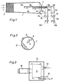
- the cooling drum 1 has an inlet 2 for the goods to be cooled and an outlet 3 where the cooled castings are removed.
- the cooled sand trickles through perforations at the outlet end of the cooling drum 1 on a conveyor belt.
- the infrared camera 4a is installed for the first measuring range, seen from the inlet.
- the optics of this infrared camera 4a (as well as any other infrared camera 4), as can be seen in FIG. 2, is preferably directed to a central location or a location of approximately the greatest thickness of the refrigerated goods 11, as is the result of the , the rotation of the cooling drum indicated by the arrow (see FIG. 2).
- the measuring object distance depends on the optics used.
- the first measuring and water metering area should be where the water brought along by the sand has largely evaporated and the lumps of sand coming out of the mold have disintegrated.
- the electrical line 15a leads from the infrared camera 4a or its built-in transmitter to the control device 5a.
- a control signal is formed and given to the positioner 6a of the motorized, hydraulically or pneumatically operated metering valve 7a in the water supply line 8a. Pneumatic positioners are preferably used.
- the individual measured value signals or an average of several successive measured value signals can be used to form the control signal.
- a plurality of infrared cameras can be used for each measuring and metering area, from whose measured value signals an average is formed.
- the water supply line 8a is led into the interior of the cooling drum 1, where it is opti through one or more outlet pipes, spray or spray nozzles 9a for the desired cooling and cohesion effect delivers the amount of water.
- the outlet pipes, spray or spray nozzles 9 are directed upward so that their mouths are above the water supply line 8a.
- shut-off valve 10a In the direction of flow before the metering valve 7a there is the shut-off valve 10a, with which the water supply is interrupted immediately when the cooling drum is at a standstill. It is advantageous to use an electromagnetically operated shut-off valve which is controlled by the control current of the cooling drum drive.
- the zero position of the metering valve 7a can be regulated.
- the device works fully automatically in such a way that the current temperature acts immediately and therefore very quickly and reliably on the water supply or its metering, and that only so much water is added per measuring and metering area that the sand remains capable of traveling, but not too dry becomes.
- a second measuring range with an independently operating metering system is also provided.
- This is constructed in the same way as the system described above and includes the infrared camera 4b, the electrical line 15b, the control device 5b, the positioner 6b, the metering valve 7b, the water supply line 8b, the outlet pipes, spray or spray nozzles 9b and that Shut-off valve 10b.
- the distance between the two measuring and dosing areas is dimensioned such that after the water added in the first area has largely evaporated, further water is added in the second area depending on the temperature measured there.
- the drum length and diameter as well as the speed of rotation also play a role.
- the arrangement of two and possibly even more ranges means that the temperature conditions in the interior of the cooling drum, or the ones introduced, are constantly and often irregularly changing both at the entrance and during the passage Amount of heat better recorded, so that the amount of water required just there is supplied to the cooling drum at every point and optimum cooling is achieved.
- multiple equipment e.g. Length, diameter, operating speed and other design and operating features of the cooling drum as well as the type of casting program are decisive.
- infrared cameras which in addition to the normal cooling jacket are provided with a further jacket through which compressed air is passed so that it exits around the camera lens and has a flow direction such that dust, vapors and gases are not used Lens can reach.
- 3 shows the diagram of such a camera.
- the infrared camera 4 is surrounded by a protective housing 12 so that a space is formed around the outer walls of the camera. Compressed air is introduced through the inlet connection 13 and flows around the camera, as indicated by the arrows, and flows out around the optics and then flows out through the protective tube 16 extending beyond the optics. 14 with the connecting cable and 17 with the pipeline for the flow medium of the normal cooling system.
- the protective housing 12 is also used for thermal insulation and protection against mechanical damage.
- the invention offers the advantage that for every casting program, every ratio of sand to metal and every casting size, the optimal amount of water is supplied fully automatically, this automatic also being fully effective in all irregularities that are unavoidable in the foundry operation and when the casting program is changed and the water supply is achieved in a matter of seconds adapts to the current situation.
- the device is structurally simple and adaptable, on the one hand to all cooling drum constructions, on the other hand to all operating characteristics.
Landscapes
- Engineering & Computer Science (AREA)
- Mechanical Engineering (AREA)
- Molds, Cores, And Manufacturing Methods Thereof (AREA)
- Casting Devices For Molds (AREA)
- Thermotherapy And Cooling Therapy Devices (AREA)
- Sampling And Sample Adjustment (AREA)
Priority Applications (1)
| Application Number | Priority Date | Filing Date | Title |
|---|---|---|---|
| AT80101056T ATE1570T1 (de) | 1979-03-07 | 1980-03-03 | Verfahren und vorrichtung zur automatischen wasserdosierung zum betreiben einer giessereikuehltrommel fuer das gleichzeitige kuehlen von form- und kernsand und guss. |
Applications Claiming Priority (2)
| Application Number | Priority Date | Filing Date | Title |
|---|---|---|---|
| DE2908861 | 1979-03-07 | ||
| DE2908861A DE2908861C3 (de) | 1979-03-07 | 1979-03-07 | Verfahren und Vorrichtung zur automatischen Wasserdosierung beim Betreiben einer Gießereikühltrommel für das gleichzeitige Kühlen von Form- und Kernsand und Guß |
Publications (2)
| Publication Number | Publication Date |
|---|---|
| EP0015530A1 EP0015530A1 (de) | 1980-09-17 |
| EP0015530B1 true EP0015530B1 (de) | 1982-09-22 |
Family
ID=6064696
Family Applications (1)
| Application Number | Title | Priority Date | Filing Date |
|---|---|---|---|
| EP80101056A Expired EP0015530B1 (de) | 1979-03-07 | 1980-03-03 | Verfahren und Vorrichtung zur automatischen Wasserdosierung zum Betreiben einer Giessereikühltrommel für das gleichzeitige Kühlen von Form- und Kernsand und Guss |
Country Status (4)
| Country | Link |
|---|---|
| EP (1) | EP0015530B1 (da) |
| AT (1) | ATE1570T1 (da) |
| DE (1) | DE2908861C3 (da) |
| DK (1) | DK160679C (da) |
Families Citing this family (2)
| Publication number | Priority date | Publication date | Assignee | Title |
|---|---|---|---|---|
| JPH06126383A (ja) * | 1992-10-23 | 1994-05-10 | Sintokogio Ltd | 金型鋳造設備における金型温度の制御方法およびその装置 |
| US5505247A (en) * | 1993-05-21 | 1996-04-09 | General Kinematics Corporation | Casting process and system |
Family Cites Families (8)
| Publication number | Priority date | Publication date | Assignee | Title |
|---|---|---|---|---|
| AT227978B (de) * | 1957-07-11 | 1963-06-25 | Dietert Co Harry W | Einrichtung zum Regulieren des Feuchtigkeitsgehaltes von körnigem Schüttgut |
| DE1808998C3 (de) * | 1968-11-15 | 1972-01-20 | Kurt Ahrenberg | Verfahren und Vorrichtung zur automatischen Befeuchtung von Mischguetern |
| US3599649A (en) * | 1969-04-10 | 1971-08-17 | Nat Eng Co | Apparatus for cooling granular material |
| NL7309900A (nl) * | 1973-07-16 | 1975-01-20 | Expert Nv | Koelerdroger van gietstukken en vormzand. |
| DE2607265C3 (de) * | 1976-02-23 | 1979-04-19 | Mec-Fond S.P.A., S. Prospero, Modena (Italien) | Vorrichtung zum Kühlen von Gußteilen und Formsand |
| DE2651154B1 (de) * | 1976-11-09 | 1977-12-29 | Fischer Ag Georg | Einrichtung zur temperaturkompensation bei der regelung der formbarkeit von koernigem material |
| DE2702301A1 (de) * | 1977-01-21 | 1978-07-27 | Polysius Ag | Verfahren und einrichtung zur bestimmung der temperaturverhaeltnisse bei einem drehrohrofen |
| GB1603082A (en) * | 1977-05-27 | 1981-11-18 | Wallwork & Co Ltd Henry | Casting installations |
-
1979
- 1979-03-07 DE DE2908861A patent/DE2908861C3/de not_active Expired
-
1980
- 1980-03-03 EP EP80101056A patent/EP0015530B1/de not_active Expired
- 1980-03-03 AT AT80101056T patent/ATE1570T1/de not_active IP Right Cessation
- 1980-03-06 DK DK097480A patent/DK160679C/da active
Also Published As
| Publication number | Publication date |
|---|---|
| DE2908861A1 (de) | 1980-09-18 |
| DE2908861C3 (de) | 1981-12-17 |
| EP0015530A1 (de) | 1980-09-17 |
| DE2908861B2 (de) | 1981-04-16 |
| DK97480A (da) | 1980-09-08 |
| DK160679B (da) | 1991-04-08 |
| ATE1570T1 (de) | 1982-10-15 |
| DK160679C (da) | 1991-09-23 |
Similar Documents
| Publication | Publication Date | Title |
|---|---|---|
| DE69837835T2 (de) | Verfahren und Vorrichtung zur Vorbereitung der Wände einer Giessform für den nächsten Vorgang zum Formen und zur Formgebung, Sprühvorrichtung mit zentrifugalen Zerstäubern und Luftzuführung, und deren Anwendung zur Zerstäubung von einem im wesentlichen lösungsmittelfreien Formwandbehandlungsmittel | |
| DE69915642T2 (de) | Verfahren zur steuerung der temperatur einer klimakammer und klimaanlage | |
| DE4417808C2 (de) | Verfahren zum Stranggießen eines Metallstranges | |
| EP0015530B1 (de) | Verfahren und Vorrichtung zur automatischen Wasserdosierung zum Betreiben einer Giessereikühltrommel für das gleichzeitige Kühlen von Form- und Kernsand und Guss | |
| DE69026103T2 (de) | Verfahren und vorrichtung zum rotationsschmelzen | |
| DE2430145C3 (da) | ||
| DE3532763A1 (de) | Verfahren und vorrichtung zum automatischen vergiessen von fluessigem metall | |
| DE2430145B2 (de) | Vorrichtung zum kuehlen eines heissen koernigen materials mittels eines zylinder-kuehlers, in dem wenigstens ein thermoelement zur messung der gutstemperatur angeordnet ist | |
| CH347610A (de) | Verfahren und Vorrichtung zum Giessen eines fortlaufenden Metallstreifens unmittelbar aus flüssigem Metall | |
| EP0828984A1 (de) | Antriebssystem für wasserlanzenbläser mit gehäuse für sperr- und spülmedium und verfahren zum betrieb | |
| DE1596571A1 (de) | Verfahren zur Steuerung des Gasdruckes in einem Glasschmelzofen | |
| EP0287597B1 (de) | Vorrichtung zum messen und regeln der temperatur in schmelzezuführungsleitungen zur herstellung von spritzgussteilen | |
| WO2020002065A1 (de) | Verfahren zum herstellen eines meltblown-vlieses und eine meltblown-anlage | |
| DE1504725A1 (de) | Vorrichtung zur Herstellung von Kunstoffrohren | |
| EP1491319A1 (de) | Verfahren und Vorrichtung zur Blasfolienherstellung | |
| DD146847A1 (de) | Kuehltunnel fuer die gesteuerte zwangskuehlung von erhitztem gut,insbesondere von gussstuecken | |
| DE1679803B1 (de) | Vorrichtung zum unterwasser-granulieren von thermoplastischem material | |
| DE2732012C2 (de) | Verfahren zur Herstellung von Glasfasern | |
| DE3536788C2 (de) | Fahrbare Ausbruchmaschine | |
| DE1964273B2 (de) | Verfahren und Vorrichtung zur Steuerung des Wärmeübergangs an einen länglichen Körper | |
| DE1956550B2 (de) | Vorrichtung zur schmelzenzufuhr fuer eine giessanordnung zum stranggiessen von draht | |
| DE3100028A1 (de) | Kuehltunnel fuer die gesteuerte zwangskuehlung von erhitztem gut, insbesondere von gussstuecken | |
| DE1652406A1 (de) | Geraet zum Bespruehen von Gegenstaenden mit einer Fluessigkeit | |
| DE454877C (de) | Einrichtung zum ununterbrochen fortlaufenden Ziehen von Roehren oder Staeben aus Glas | |
| DE3419769C2 (da) |
Legal Events
| Date | Code | Title | Description |
|---|---|---|---|
| PUAI | Public reference made under article 153(3) epc to a published international application that has entered the european phase |
Free format text: ORIGINAL CODE: 0009012 |
|
| AK | Designated contracting states |
Designated state(s): AT BE CH FR GB IT LU NL SE |
|
| 17P | Request for examination filed |
Effective date: 19801027 |
|
| ITF | It: translation for a ep patent filed | ||
| GRAA | (expected) grant |
Free format text: ORIGINAL CODE: 0009210 |
|
| AK | Designated contracting states |
Designated state(s): AT BE CH FR GB IT LU NL SE |
|
| REF | Corresponds to: |
Ref document number: 1570 Country of ref document: AT Date of ref document: 19821015 Kind code of ref document: T |
|
| PG25 | Lapsed in a contracting state [announced via postgrant information from national office to epo] |
Ref country code: LU Free format text: LAPSE BECAUSE OF NON-PAYMENT OF DUE FEES Effective date: 19830331 |
|
| REG | Reference to a national code |
Ref country code: CH Ref legal event code: PUE Owner name: CARL SCHENCK AG |
|
| REG | Reference to a national code |
Ref country code: FR Ref legal event code: TP |
|
| ITPR | It: changes in ownership of a european patent |
Owner name: CESSIONE;CARL SCHENCK AG |
|
| PGFP | Annual fee paid to national office [announced via postgrant information from national office to epo] |
Ref country code: FR Payment date: 19840215 Year of fee payment: 5 |
|
| REG | Reference to a national code |
Ref country code: GB Ref legal event code: 732 |
|
| PGFP | Annual fee paid to national office [announced via postgrant information from national office to epo] |
Ref country code: SE Payment date: 19840331 Year of fee payment: 5 |
|
| PGFP | Annual fee paid to national office [announced via postgrant information from national office to epo] |
Ref country code: LU Payment date: 19860404 Year of fee payment: 7 |
|
| PGFP | Annual fee paid to national office [announced via postgrant information from national office to epo] |
Ref country code: AT Payment date: 19870209 Year of fee payment: 8 |
|
| PG25 | Lapsed in a contracting state [announced via postgrant information from national office to epo] |
Ref country code: AT Effective date: 19880303 |
|
| PG25 | Lapsed in a contracting state [announced via postgrant information from national office to epo] |
Ref country code: SE Effective date: 19880304 |
|
| PG25 | Lapsed in a contracting state [announced via postgrant information from national office to epo] |
Ref country code: FR Free format text: LAPSE BECAUSE OF NON-PAYMENT OF DUE FEES Effective date: 19881130 |
|
| REG | Reference to a national code |
Ref country code: FR Ref legal event code: ST |
|
| PGFP | Annual fee paid to national office [announced via postgrant information from national office to epo] |
Ref country code: CH Payment date: 19940211 Year of fee payment: 15 |
|
| PGFP | Annual fee paid to national office [announced via postgrant information from national office to epo] |
Ref country code: BE Payment date: 19940224 Year of fee payment: 15 |
|
| PGFP | Annual fee paid to national office [announced via postgrant information from national office to epo] |
Ref country code: NL Payment date: 19940331 Year of fee payment: 15 |
|
| EUG | Se: european patent has lapsed |
Ref document number: 80101056.2 Effective date: 19881201 |
|
| PG25 | Lapsed in a contracting state [announced via postgrant information from national office to epo] |
Ref country code: CH Effective date: 19950331 Ref country code: BE Effective date: 19950331 |
|
| BERE | Be: lapsed |
Owner name: CARL SCHENCK A.G. Effective date: 19950331 |
|
| PG25 | Lapsed in a contracting state [announced via postgrant information from national office to epo] |
Ref country code: NL Effective date: 19951001 |
|
| REG | Reference to a national code |
Ref country code: CH Ref legal event code: PL |
|
| NLV4 | Nl: lapsed or anulled due to non-payment of the annual fee |
Effective date: 19951001 |
|
| PGFP | Annual fee paid to national office [announced via postgrant information from national office to epo] |
Ref country code: GB Payment date: 19960216 Year of fee payment: 17 |
|
| PG25 | Lapsed in a contracting state [announced via postgrant information from national office to epo] |
Ref country code: GB Effective date: 19970303 |
|
| GBPC | Gb: european patent ceased through non-payment of renewal fee |
Effective date: 19970303 |
|
| PLBE | No opposition filed within time limit |
Free format text: ORIGINAL CODE: 0009261 |
|
| STAA | Information on the status of an ep patent application or granted ep patent |
Free format text: STATUS: NO OPPOSITION FILED WITHIN TIME LIMIT |