EP0015742A1 - Turbine à vapeur humide - Google Patents
Turbine à vapeur humide Download PDFInfo
- Publication number
- EP0015742A1 EP0015742A1 EP80300654A EP80300654A EP0015742A1 EP 0015742 A1 EP0015742 A1 EP 0015742A1 EP 80300654 A EP80300654 A EP 80300654A EP 80300654 A EP80300654 A EP 80300654A EP 0015742 A1 EP0015742 A1 EP 0015742A1
- Authority
- EP
- European Patent Office
- Prior art keywords
- turbine
- water
- vanes
- rotor
- steam
- Prior art date
- Legal status (The legal status is an assumption and is not a legal conclusion. Google has not performed a legal analysis and makes no representation as to the accuracy of the status listed.)
- Granted
Links
- XLYOFNOQVPJJNP-UHFFFAOYSA-N water Substances O XLYOFNOQVPJJNP-UHFFFAOYSA-N 0.000 claims abstract description 62
- 239000007788 liquid Substances 0.000 claims abstract description 29
- 239000000203 mixture Substances 0.000 claims abstract description 14
- 239000012530 fluid Substances 0.000 claims description 17
- 238000010438 heat treatment Methods 0.000 claims description 8
- 238000005192 partition Methods 0.000 claims description 2
- 238000003303 reheating Methods 0.000 claims description 2
- 239000008400 supply water Substances 0.000 claims 3
- 238000002347 injection Methods 0.000 claims 1
- 239000007924 injection Substances 0.000 claims 1
- 238000010276 construction Methods 0.000 abstract description 3
- 239000000446 fuel Substances 0.000 abstract description 3
- 229920006395 saturated elastomer Polymers 0.000 description 7
- 238000010586 diagram Methods 0.000 description 6
- 230000001133 acceleration Effects 0.000 description 3
- 239000002826 coolant Substances 0.000 description 3
- 230000003068 static effect Effects 0.000 description 3
- 238000007599 discharging Methods 0.000 description 2
- 230000001172 regenerating effect Effects 0.000 description 2
- 239000007787 solid Substances 0.000 description 2
- 230000003190 augmentative effect Effects 0.000 description 1
- 238000006243 chemical reaction Methods 0.000 description 1
- 238000009833 condensation Methods 0.000 description 1
- 230000005494 condensation Effects 0.000 description 1
- 230000008878 coupling Effects 0.000 description 1
- 238000010168 coupling process Methods 0.000 description 1
- 238000005859 coupling reaction Methods 0.000 description 1
- 230000005574 cross-species transmission Effects 0.000 description 1
- 125000004122 cyclic group Chemical group 0.000 description 1
- 230000000694 effects Effects 0.000 description 1
- 239000002803 fossil fuel Substances 0.000 description 1
- 239000008240 homogeneous mixture Substances 0.000 description 1
- 238000012423 maintenance Methods 0.000 description 1
- 238000000034 method Methods 0.000 description 1
- 239000000126 substance Substances 0.000 description 1
- 230000007704 transition Effects 0.000 description 1
- 238000011144 upstream manufacturing Methods 0.000 description 1
- 239000002918 waste heat Substances 0.000 description 1
Images

Classifications
-
- F—MECHANICAL ENGINEERING; LIGHTING; HEATING; WEAPONS; BLASTING
- F01—MACHINES OR ENGINES IN GENERAL; ENGINE PLANTS IN GENERAL; STEAM ENGINES
- F01D—NON-POSITIVE DISPLACEMENT MACHINES OR ENGINES, e.g. STEAM TURBINES
- F01D1/00—Non-positive-displacement machines or engines, e.g. steam turbines
-
- F—MECHANICAL ENGINEERING; LIGHTING; HEATING; WEAPONS; BLASTING
- F01—MACHINES OR ENGINES IN GENERAL; ENGINE PLANTS IN GENERAL; STEAM ENGINES
- F01D—NON-POSITIVE DISPLACEMENT MACHINES OR ENGINES, e.g. STEAM TURBINES
- F01D1/00—Non-positive-displacement machines or engines, e.g. steam turbines
- F01D1/32—Non-positive-displacement machines or engines, e.g. steam turbines with pressure velocity transformation exclusively in rotor, e.g. the rotor rotating under the influence of jets issuing from the rotor, e.g. Heron turbines
-
- F—MECHANICAL ENGINEERING; LIGHTING; HEATING; WEAPONS; BLASTING
- F01—MACHINES OR ENGINES IN GENERAL; ENGINE PLANTS IN GENERAL; STEAM ENGINES
- F01K—STEAM ENGINE PLANTS; STEAM ACCUMULATORS; ENGINE PLANTS NOT OTHERWISE PROVIDED FOR; ENGINES USING SPECIAL WORKING FLUIDS OR CYCLES
- F01K21/00—Steam engine plants not otherwise provided for
- F01K21/005—Steam engine plants not otherwise provided for using mixtures of liquid and steam or evaporation of a liquid by expansion
Definitions
- This invention is concerned with a new class of heat engines where the working fluid, for example steam, is used in its two-phase region with vapor and liquid occurring simultaneously for at least part of.the cycle, in particular the nozzle expansion.
- the fields of use are primarily those where lower speeds and high torques are required, for example, as a prime mover driving an electric generator, an engine for marine and land propulsion, and generally as units of small power output. No restrictions are imposed on the heat source, which may be utilizing fossil fuels burned in air, waste heat, solar heat, or nuclear reaction heat and so on.
- the proposed turbine is related to existing steam turbine engines; however, as a consequence of using large fractions of liquid in the expanding part of the cycle, a much smaller number of stages may usually be required, and the turbine may handle liquid only. Also, the thermodynamic cycle may be altered considerably from the usual Rankine cycle, inasmuch as the expansion is taking place near the liquid line of the temperature-entropy diagram, as described below.
- the present turbine is intended to use a single-component working fluid, as for example water, to simplify the working fluid storage and handling, and to improve engine reliability by employing well proven working media of high chemical stability.
- a turbine is characterised by first nozzle means for expanding wet steam supplied from a heating means, a turbine rotor having first vanes to receive and pass water supplied via the first nozzle means and for forming a ring of water proximate said first vanes, the rotor also having second vanes to which steam is supplied via the first nozzle means, rotary means to receive feed water and to pressurize same, a recuperative zone communicating with said rotary means and with said second vanes to receive pressurized feed water and steam that has passed said second vanes for fluid mixing in said zone and for enabling direct heat exchange from the steam to the feed water, and means for withdrawing fluid mix from said zone for reheating by said heating means to produce wet steam for expansion in said first nozzle means.
- the invention provides an economical prime mover of low capital cost due to simple construction, low fuel consumption, high reliability, and minimum maintenance requirements.
- the objective of low fuel consumption is achieved in that the heat engine cycle is "Carnotized", in a fashion similar to regenerative feed-water preheating, by extracting expanding steam from the turbine in order to preheat feed water by condensation of the extracted steam. Since the pressure of the heat emitting condensing vapor and the heat absorbing feed-water can be made the same, a direct-contact heat exchanger is used, which is of high effectiveness and typically of very small size.
- the expanding steam may be of low quality, typically of 10% to 20% mass fraction of vapor in the total wet mixture flow.
- the enthalpy change across the first nozzle means is reduced to such a degree that a two-stage turbine, for example, is able to handle the entire expansion head at moderate stress levels.
- comparable conventional impulse steam turbines would require about fifteen stages.
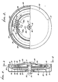
- FIG. 1 is an axial vertical elevation, in section, schematically showing a two-stage liquid turbine with recuperator in accordance with the invention
- FIGS. 1 to 3 show a prime mover in the form of a turbine which includes fixed, non-rotating structure 19 including a casing 20, an output shaft 21 rotatable about axis 22 to drive and do work upon external device 23; rotary structure 24 within the casing and directly connected to shaft 21; and a free wheeling rotor 25 within the casing.
- a bearing 26 mounts the rotor 25 to a casing flange 20a; a bearing 27 centers shaft 21 in the casing bore 20b; bearings 28 and 29 mount structure 24 on fixed structure 19; and bearing 30 centers rotor 25 relative to structure 24.
- First nozzle means as for example nozzle box 32, is associated with the fixed structure 19, and is supplied with wet steam for expansion in the box.
- the nozzle box 32 typically includes a series of nozzle segments 32a spaced about axis 22 and located between parallel walls 33 which extend in planes which are normal to that axis.
- the nozzles define venturis, including convergent portion 34, throat 35 and divergent portion 36.
- Walls 33 are integral with fixed structure 19.
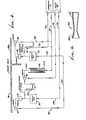
- Wet steam may be supplied from boiler BB along paths 135 and 136 to the nozzle box.
- Figs. 2 and 3 show the provision of fluid injectors 37 operable to inject fluid such as water into the wet steam path as defined by annular manifold 33, immediately upstream of the nozzles 32.
- Such fluid may be supplied via a fluid inlet 38 to a ringshaped manifold 39 to which the injectors are connected.
- Such injectors provide good droplet distribution in the wet steam, for optimum turbine operating efficiency, expansion of the steam through the nozzles accelerating the water droplets for maximum impulse delivery to the turbine vanes 42.
- a steam inlet is shown at 136a.
- Rotary turbine structure 24 provides first vanes, as for example at 42 spaced about axis 22, to receive and pass the water droplets in the steam in the nozzle means 32.
- first vanes may extend in axial radial planes, and are typically spaced about axis 22 in circular sequence. They extend between annular walls 44 and 45 of structure 24, to which an outer closure wall 46 is joined. Wall 46 may form one or more nozzles, two being shown at 47 in Fig. 3.
- Nozzles 47 are directed generally counterclockwise in Fig. 3
- nozzles 32 are directed generally clockwise, so that turbine structure 24 rotates clockwise in Fig. 3.
- the turbine structure is basically a drum that contains a ring of liquid (i.e.
- Water collecting in region 51 impinges on the freely rotating rotor 55 extending about turbine rotor structure 24, and tends to rotate that rotor with a rotating ring of water collecting at 56.
- a non-rotating scoop 57 extending into zone 51 collects water at the inner surface of the ring 56, the scoop communicating with second nozzle means 58 to be described, as via ducts or paths 159 to 163. Accordingly, expanded first stage liquid (captured by free-wheeling drum or rotor 55 and scooped up by pitot opening 57) may be supplied in pressurized state to the inlet of second stage nozzle 58.
- rotary means to receive feed water and to centrifugally pressurize same.
- Such means may-take the form of a centrifugal rotary pump 60 mounted as by bearings 61 to fixed structure 19.
- the pump may include a series of discs 62 which are normal to axis 22, and which are located within and rotate with pump casing 63 rotating at the same speed as the turbine structure 24.
- a connection 64 may extend between casing 63 and the turbine 24.
- the discs of such a pump are closely spaced apart so as to allow the liquid or water discharge from inlet spout 65 to distribute generally uniformly among the individual slots between the plates and to flow radially outwardly, while gaining pressure.
- a recuperative zone 66 is provided inwardly of the turbine wall structure 24a to communicate with the discharge 60a of rotating pump 60, and with the nozzle box 32 via a series of steam passing vanes 68.
- the latter are connected to the turbine rotor wall 24b to receive and pass steam discharging from nozzles 32, imparting further torque to the turbine rotor.
- the steam is drawn into direct heat exchange contact with the water droplets spun-off from the pump 60, in heat exchange, or recuperative zone 66. Both liquid droplets and steam have equal swirl velocity and are at equal static pressure in rotating zone 66, as they mix therein.
- a scoop 70 may be associated. with fixed structure 19, and extend into zone 66 to withdraw the fluid mix for supply via fixed ducts 71 and 72 to boiler or heater BB, from which the fluid mix is returned via path 135 to the nozzle means 32.
- the second stage nozzle means 58 receives water from scoop 57, as previously described, and also steam spill-over from space 66, as via paths 74 and 75 adjacent turbine wall 24c. Such pressurized steam mixed with liquid from scoop 57 is expanded in the second nozzle means 58 producing vapor and water, the vapor being ducted via paths 78 and 79 to condenser CC. Fourth vanes 81 attached to rotating turbine wall 24d receive pressure application from the flowing steam to extract energy from the steam and to develop additional torque. The condensate from the condenser is returned via path 83 to the inlet 65 of pump 60.
- the water from nozzle means 58 collects in a rotating ring in region 84, imparting torque to vanes 85 in that region bounded by turbine rotor walls 86 and 87, and outer wall 88.
- the construction may be the same as that of the first nozzle means 32, water ring 50, vanes 42 and walls 44 to 46.
- Nozzles 89 discharge water from the rotating ring in region 84, and correspond to nozzles 47.
- Free wheeling rotor 55 extends at 55a about nozzles 89, and collects water discharging from the latter, forming a ring in zone 91 due to centrifugal effect.
- Non- rotary scoop 90 collects water in the ring formed by rotor extent 55a, and ducts it at 92 to path 83 for return to the Tesla pump 60,
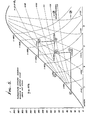
- Wet steam of condition A i.e. of dryness fraction 0.2
- nozzle box 32 Fig. 1
- the special two-phase nozzles used the expanding vapor for the acceleration of the liquid droplets so that the mixture of wet steam and water will enter the turbine ring 42 (Fig. 3) at nearly uniform velocity, with the steam at the thermodynamic condition B.
- the liquid will then separate from the vapor and issue through the nozzles 47 (Fig. 3) and collect in a rotating ring in the drum 55 (Fig. 1).
- the scoop 57 will deliver collected liquid to the nozzle box 58 at condition .
- the saturated expanded steam from nozzle 32 at a condition (off the diagram to the right) in the meantime will drive vanes 68 and enter the recuperator 66.
- the vapor will be partially condensed by direct contact with feed-water originally at condition E from scoop 90 in Fig. 1, mixed with condensate as it is returned from the condenser CC.
- Both streams of liquid (at condition E) whether supplied by scoop 90 or that returning from the condenser CC are pumped up at 60 to the static pressure of the steam entering zone 66 (Fig. 1).
- the heat exchange by direct contact occurs across the surfaces of spherical droplets that are spun-off from the rotating discs of the Tesla pump, and into zone 66.
- the heated liquid of condition that is derived from preheating by the steam and augmented by condensate formed at condition is scooped up at 70 and returned to the boiler BB by stationary lines 71 and 72.
- the mixture will be at a condition C, corresponding to the total amount of preheated liquid of condition and saturated vapor of condition .
- the subsequent nozzle expansion at 58 from condition C to D results in similar velocities as produced in the expansion A to B in nozzle 32.
- the issuing jet can therefore drive the second liquid turbine efficiently at the speed of the first turbine, so that direct coupling of the two stages is possible.
- the turbine described in Fig. 1 is a two-stage turbine with only one intermediate recuperator.
- An analysis of the efficiency of the thermodynamic cycle shows that the performance of such a turbine is improved among others by two factors:
- a more conventional turbine with buckets around the periphery may be employed and which admits a homogeneous mixture of saturated steam and saturated water droplets.
- the converging-diverging nozzle may be designed with a sharp-edged throat as a transition from a straight converging cone 200 to a straight diverging cone 201. See Fig. 6 showing such a nozzle 202.
- Fig. 1 also shows annular partition 95 integral with rotor 55, and separating rotary ring of water 56 from rotary ring 91 of water.
Landscapes
- Engineering & Computer Science (AREA)
- Mechanical Engineering (AREA)
- General Engineering & Computer Science (AREA)
- Chemical & Material Sciences (AREA)
- Combustion & Propulsion (AREA)
- Engine Equipment That Uses Special Cycles (AREA)
- Turbine Rotor Nozzle Sealing (AREA)
- Control Of Turbines (AREA)
- Organic Low-Molecular-Weight Compounds And Preparation Thereof (AREA)
- Centrifugal Separators (AREA)
- Massaging Devices (AREA)
- Heat Treatment Of Steel (AREA)
- Production Of Liquid Hydrocarbon Mixture For Refining Petroleum (AREA)
Priority Applications (1)
| Application Number | Priority Date | Filing Date | Title |
|---|---|---|---|
| AT80300654T ATE8691T1 (de) | 1979-03-05 | 1980-03-05 | Nassdampfturbine. |
Applications Claiming Priority (2)
| Application Number | Priority Date | Filing Date | Title |
|---|---|---|---|
| US06/017,456 US4258551A (en) | 1979-03-05 | 1979-03-05 | Multi-stage, wet steam turbine |
| US17456 | 1979-03-05 |
Related Child Applications (2)
| Application Number | Title | Priority Date | Filing Date |
|---|---|---|---|
| EP82110991.5 Division-Into | 1980-03-05 | ||
| EP82110991A Division EP0075965A3 (fr) | 1979-03-05 | 1980-03-05 | Turbine |
Publications (2)
| Publication Number | Publication Date |
|---|---|
| EP0015742A1 true EP0015742A1 (fr) | 1980-09-17 |
| EP0015742B1 EP0015742B1 (fr) | 1984-07-25 |
Family
ID=21782689
Family Applications (2)
| Application Number | Title | Priority Date | Filing Date |
|---|---|---|---|
| EP80300654A Expired EP0015742B1 (fr) | 1979-03-05 | 1980-03-05 | Turbine à vapeur humide |
| EP82110991A Withdrawn EP0075965A3 (fr) | 1979-03-05 | 1980-03-05 | Turbine |
Family Applications After (1)
| Application Number | Title | Priority Date | Filing Date |
|---|---|---|---|
| EP82110991A Withdrawn EP0075965A3 (fr) | 1979-03-05 | 1980-03-05 | Turbine |
Country Status (8)
| Country | Link |
|---|---|
| US (1) | US4258551A (fr) |
| EP (2) | EP0015742B1 (fr) |
| JP (2) | JPS55142906A (fr) |
| AT (1) | ATE8691T1 (fr) |
| AU (1) | AU538771B2 (fr) |
| CA (1) | CA1159264A (fr) |
| DE (1) | DE3068644D1 (fr) |
| MX (1) | MX149885A (fr) |
Cited By (4)
| Publication number | Priority date | Publication date | Assignee | Title |
|---|---|---|---|---|
| EP0032815A3 (en) * | 1980-01-17 | 1981-08-12 | Transamerica Delaval, Inc. | Two-phase reaction turbine |
| JPS6193246U (fr) * | 1984-11-22 | 1986-06-16 | ||
| EP0213586A1 (fr) * | 1985-08-29 | 1987-03-11 | Fuji Electric Co., Ltd. | Turbine à eau chaude et vapeur |
| WO2001055561A1 (fr) * | 2000-01-27 | 2001-08-02 | Yankee Scientific, Inc. | Systeme de cogeneration de petite dimension conçu pour produire de l'energie thermique et electrique |
Families Citing this family (48)
| Publication number | Priority date | Publication date | Assignee | Title |
|---|---|---|---|---|
| US4441322A (en) * | 1979-03-05 | 1984-04-10 | Transamerica Delaval Inc. | Multi-stage, wet steam turbine |
| US4463567A (en) * | 1982-02-16 | 1984-08-07 | Transamerica Delaval Inc. | Power production with two-phase expansion through vapor dome |
| US4502839A (en) * | 1982-11-02 | 1985-03-05 | Transamerica Delaval Inc. | Vibration damping of rotor carrying liquid ring |
| JPS59126001A (ja) * | 1982-12-30 | 1984-07-20 | Mitsui Eng & Shipbuild Co Ltd | 反動式二相流タ−ビン装置 |
| US4511309A (en) * | 1983-01-10 | 1985-04-16 | Transamerica Delaval Inc. | Vibration damped asymmetric rotor carrying liquid ring or rings |
| US5027602A (en) * | 1989-08-18 | 1991-07-02 | Atomic Energy Of Canada, Ltd. | Heat engine, refrigeration and heat pump cycles approximating the Carnot cycle and apparatus therefor |
| US5385446A (en) * | 1992-05-05 | 1995-01-31 | Hays; Lance G. | Hybrid two-phase turbine |
| US5664420A (en) | 1992-05-05 | 1997-09-09 | Biphase Energy Company | Multistage two-phase turbine |
| US6090299A (en) * | 1996-05-30 | 2000-07-18 | Biphase Energy Company | Three-phase rotary separator |
| US5750040A (en) * | 1996-05-30 | 1998-05-12 | Biphase Energy Company | Three-phase rotary separator |
| US5685691A (en) * | 1996-07-01 | 1997-11-11 | Biphase Energy Company | Movable inlet gas barrier for a free surface liquid scoop |
| US6890142B2 (en) | 2001-10-09 | 2005-05-10 | James G. Asseken | Direct condensing turbine |
| US6892539B2 (en) * | 2003-01-06 | 2005-05-17 | John Warner Jarman | Rotary heat engine |
| US8075668B2 (en) * | 2005-03-29 | 2011-12-13 | Dresser-Rand Company | Drainage system for compressor separators |
| US7731480B2 (en) * | 2006-04-07 | 2010-06-08 | Benjamin J Cooper | Efficient power turbine and electrical generation system |
| BRPI0716867A2 (pt) * | 2006-09-19 | 2013-10-15 | Dresser Rand Co | Vedação de tambor de separador rotativo |
| MX2009003119A (es) * | 2006-09-21 | 2009-04-06 | Dresser Rand Co | Tambor separador y ensamble propulsor de compresor. |
| EP2066983B1 (fr) * | 2006-09-25 | 2013-12-11 | Dresser-Rand Company | Système de montage pour compresseur |
| EP2066988A4 (fr) * | 2006-09-25 | 2012-01-04 | Dresser Rand Co | Système de protection de couplage |
| WO2008039446A2 (fr) * | 2006-09-25 | 2008-04-03 | Dresser-Rand Company | Déflecteur à fluides destiné à des dispositifs de séparation de fluides |
| EP2066949B1 (fr) * | 2006-09-25 | 2013-08-28 | Dresser-Rand Company | Connexion à tiroir mobile axialement |
| MX2009003175A (es) * | 2006-09-25 | 2009-04-03 | Dresser Rand Co | Cubierta de acceso para bobina conectora presurizada. |
| EP2066422B1 (fr) * | 2006-09-26 | 2012-06-27 | Dresser-Rand Company | Dispositif de séparation de fluides statique amélioré |
| BRPI0908051A2 (pt) * | 2008-03-05 | 2015-08-11 | Dresser Rand Co | Conjunto compressor que inclui separador e bomba ejetora |
| US8523539B2 (en) * | 2008-06-19 | 2013-09-03 | The Board Of Regents Of The University Of Texas Systems | Centrifugal pump |
| US8062400B2 (en) * | 2008-06-25 | 2011-11-22 | Dresser-Rand Company | Dual body drum for rotary separators |
| US8079805B2 (en) * | 2008-06-25 | 2011-12-20 | Dresser-Rand Company | Rotary separator and shaft coupler for compressors |
| US7922218B2 (en) * | 2008-06-25 | 2011-04-12 | Dresser-Rand Company | Shear ring casing coupler device |
| US8210804B2 (en) * | 2009-03-20 | 2012-07-03 | Dresser-Rand Company | Slidable cover for casing access port |
| US8087901B2 (en) * | 2009-03-20 | 2012-01-03 | Dresser-Rand Company | Fluid channeling device for back-to-back compressors |
| US8061972B2 (en) * | 2009-03-24 | 2011-11-22 | Dresser-Rand Company | High pressure casing access cover |
| BR112012005866B1 (pt) * | 2009-09-15 | 2021-01-19 | Dresser-Rand Company | aparelho para a separação de um fluido e método para a separação de um componente de peso específico mais alto de um componente de peso específico mais baixo de um fluido |
| US20110097216A1 (en) * | 2009-10-22 | 2011-04-28 | Dresser-Rand Company | Lubrication system for subsea compressor |
| EP2533905B1 (fr) | 2010-02-10 | 2018-07-04 | Dresser-Rand Company | Collecteur de fluide séparateur et procédé |
| US9314899B2 (en) | 2010-06-23 | 2016-04-19 | Puchegger Jilg Parkett Gross U. Einzelhandels Ges.M.B.H. | Grinding tool for the simultaneous sanding and polishing of floors |
| US8673159B2 (en) | 2010-07-15 | 2014-03-18 | Dresser-Rand Company | Enhanced in-line rotary separator |
| US8663483B2 (en) | 2010-07-15 | 2014-03-04 | Dresser-Rand Company | Radial vane pack for rotary separators |
| US8657935B2 (en) | 2010-07-20 | 2014-02-25 | Dresser-Rand Company | Combination of expansion and cooling to enhance separation |
| US8821362B2 (en) | 2010-07-21 | 2014-09-02 | Dresser-Rand Company | Multiple modular in-line rotary separator bundle |
| JP5936144B2 (ja) | 2010-09-09 | 2016-06-15 | ドレッサー ランド カンパニーDresser−Rand Company | 洗浄可能に制御された排水管 |
| WO2013064858A1 (fr) * | 2011-10-31 | 2013-05-10 | Heat Recovery Micro Systems Cc | Procédé et appareil de conversion d'énergie thermique en énergie mécanique |
| US9574563B2 (en) | 2013-04-09 | 2017-02-21 | Harris Corporation | System and method of wrapping flow in a fluid working apparatus |
| US9303514B2 (en) | 2013-04-09 | 2016-04-05 | Harris Corporation | System and method of utilizing a housing to control wrapping flow in a fluid working apparatus |
| US9297387B2 (en) | 2013-04-09 | 2016-03-29 | Harris Corporation | System and method of controlling wrapping flow in a fluid working apparatus |
| US9303533B2 (en) * | 2013-12-23 | 2016-04-05 | Harris Corporation | Mixing assembly and method for combining at least two working fluids |
| KR101667386B1 (ko) * | 2014-12-24 | 2016-10-19 | 포스코에너지 주식회사 | 축력 특성이 개선된 스팀 터빈 |
| CN115502745B (zh) * | 2022-09-22 | 2023-09-19 | 无锡正杰机械科技有限公司 | 一种汽车涡轮壳固定工装及固定方法 |
| CN115929431B (zh) * | 2022-12-21 | 2025-12-19 | 西安交通大学 | 一种强柔性燃煤发电系统及运行方法 |
Citations (10)
| Publication number | Priority date | Publication date | Assignee | Title |
|---|---|---|---|---|
| FR442585A (fr) * | 1912-04-16 | 1912-09-04 | Dwight Sipperley Cole | Perfectionnements aux turbines |
| GB162541A (en) * | 1920-05-04 | 1921-05-05 | Moses Solomon Okun | Improvements in or relating to hydraulic turbines |
| GB765216A (en) * | 1952-09-05 | 1957-01-09 | Dmytro Bolesta | Improvements in and relating to the generation of power |
| GB1205632A (en) * | 1967-03-28 | 1970-09-16 | William James Lithgow | Radial outflow steam turbine |
| FR2038059A1 (fr) * | 1969-03-17 | 1971-01-08 | Lemauff Gilbert | |
| FR2061881A5 (fr) * | 1969-10-01 | 1971-06-25 | Liautaud Jean | |
| US3879949A (en) * | 1972-11-29 | 1975-04-29 | Biphase Engines Inc | Two-phase engine |
| US3972195A (en) * | 1973-12-14 | 1976-08-03 | Biphase Engines, Inc. | Two-phase engine |
| US4063417A (en) * | 1976-02-04 | 1977-12-20 | Carrier Corporation | Power generating system employing geothermally heated fluid |
| US4141219A (en) * | 1977-10-31 | 1979-02-27 | Nasa | Method and turbine for extracting kinetic energy from a stream of two-phase fluid |
Family Cites Families (6)
| Publication number | Priority date | Publication date | Assignee | Title |
|---|---|---|---|---|
| US1803054A (en) * | 1926-01-09 | 1931-04-28 | Superheater Co Ltd | Method and apparatus for heating fluids |
| US3358451A (en) * | 1965-04-29 | 1967-12-19 | Joseph Kaye & Company Inc | Heat engine apparatus and method |
| US3758223A (en) * | 1971-09-30 | 1973-09-11 | M Eskeli | Reaction rotor turbine |
| US3930744A (en) * | 1973-10-10 | 1976-01-06 | Hollymatic Corporation | Pressure gas engine |
| US4106294A (en) * | 1977-02-02 | 1978-08-15 | Julius Czaja | Thermodynamic process and latent heat engine |
| US4143516A (en) * | 1977-10-25 | 1979-03-13 | Long Aden B | Air-water power generator |
-
1979
- 1979-03-05 US US06/017,456 patent/US4258551A/en not_active Expired - Lifetime
-
1980
- 1980-02-29 AU AU56016/80A patent/AU538771B2/en not_active Ceased
- 1980-03-04 CA CA000346953A patent/CA1159264A/fr not_active Expired
- 1980-03-05 EP EP80300654A patent/EP0015742B1/fr not_active Expired
- 1980-03-05 DE DE8080300654T patent/DE3068644D1/de not_active Expired
- 1980-03-05 AT AT80300654T patent/ATE8691T1/de not_active IP Right Cessation
- 1980-03-05 MX MX181433A patent/MX149885A/es unknown
- 1980-03-05 JP JP2785980A patent/JPS55142906A/ja active Pending
- 1980-03-05 EP EP82110991A patent/EP0075965A3/fr not_active Withdrawn
-
1985
- 1985-12-27 JP JP60299657A patent/JPS61192801A/ja active Pending
Patent Citations (10)
| Publication number | Priority date | Publication date | Assignee | Title |
|---|---|---|---|---|
| FR442585A (fr) * | 1912-04-16 | 1912-09-04 | Dwight Sipperley Cole | Perfectionnements aux turbines |
| GB162541A (en) * | 1920-05-04 | 1921-05-05 | Moses Solomon Okun | Improvements in or relating to hydraulic turbines |
| GB765216A (en) * | 1952-09-05 | 1957-01-09 | Dmytro Bolesta | Improvements in and relating to the generation of power |
| GB1205632A (en) * | 1967-03-28 | 1970-09-16 | William James Lithgow | Radial outflow steam turbine |
| FR2038059A1 (fr) * | 1969-03-17 | 1971-01-08 | Lemauff Gilbert | |
| FR2061881A5 (fr) * | 1969-10-01 | 1971-06-25 | Liautaud Jean | |
| US3879949A (en) * | 1972-11-29 | 1975-04-29 | Biphase Engines Inc | Two-phase engine |
| US3972195A (en) * | 1973-12-14 | 1976-08-03 | Biphase Engines, Inc. | Two-phase engine |
| US4063417A (en) * | 1976-02-04 | 1977-12-20 | Carrier Corporation | Power generating system employing geothermally heated fluid |
| US4141219A (en) * | 1977-10-31 | 1979-02-27 | Nasa | Method and turbine for extracting kinetic energy from a stream of two-phase fluid |
Cited By (4)
| Publication number | Priority date | Publication date | Assignee | Title |
|---|---|---|---|---|
| EP0032815A3 (en) * | 1980-01-17 | 1981-08-12 | Transamerica Delaval, Inc. | Two-phase reaction turbine |
| JPS6193246U (fr) * | 1984-11-22 | 1986-06-16 | ||
| EP0213586A1 (fr) * | 1985-08-29 | 1987-03-11 | Fuji Electric Co., Ltd. | Turbine à eau chaude et vapeur |
| WO2001055561A1 (fr) * | 2000-01-27 | 2001-08-02 | Yankee Scientific, Inc. | Systeme de cogeneration de petite dimension conçu pour produire de l'energie thermique et electrique |
Also Published As
| Publication number | Publication date |
|---|---|
| DE3068644D1 (en) | 1984-08-30 |
| EP0015742B1 (fr) | 1984-07-25 |
| MX149885A (es) | 1984-01-31 |
| ATE8691T1 (de) | 1984-08-15 |
| CA1159264A (fr) | 1983-12-27 |
| EP0075965A2 (fr) | 1983-04-06 |
| JPS61192801A (ja) | 1986-08-27 |
| US4258551A (en) | 1981-03-31 |
| AU538771B2 (en) | 1984-08-30 |
| EP0075965A3 (fr) | 1984-07-11 |
| AU5601680A (en) | 1980-09-11 |
| JPS55142906A (en) | 1980-11-07 |
Similar Documents
| Publication | Publication Date | Title |
|---|---|---|
| EP0015742B1 (fr) | Turbine à vapeur humide | |
| US4441322A (en) | Multi-stage, wet steam turbine | |
| US3972195A (en) | Two-phase engine | |
| US4298311A (en) | Two-phase reaction turbine | |
| US3879949A (en) | Two-phase engine | |
| AU698268B2 (en) | Hybrid two-phase turbine | |
| AU696828B2 (en) | Improved method and apparatus for power generation | |
| US4227373A (en) | Waste heat recovery cycle for producing power and fresh water | |
| US6089024A (en) | Steam-augmented gas turbine | |
| US5494355A (en) | Device for removal of lubricant from a bearing assembly | |
| US20110154822A1 (en) | Micro-scale engines, components, and methods for generating power | |
| US8671696B2 (en) | Method and apparatus for increasing thrust or other useful energy output of a device with a rotating element | |
| CN101652549A (zh) | 旋转装置 | |
| US5241815A (en) | Heat-recovering-thrust-turbine having rotational flow path | |
| US2569997A (en) | Jet device for discharging a mixture of fluids | |
| US11898469B2 (en) | Reaction turbine operating on condensing vapors | |
| US5045004A (en) | Turbo-hydroduct propulsion system | |
| CA1164228A (fr) | Turbine multi-etagee a vapeur humide | |
| US20070151246A1 (en) | Thermal combustion engine which converts thermal energy into mechanical energy and use thereof | |
| CA1160465A (fr) | Turbine multi-etagee a vapeur saturee | |
| US4060989A (en) | Thermodynamic machine with step type heat exchangers | |
| EP0098363A1 (fr) | Turbine à gaz avec surveillance de la température des aubes | |
| US2075648A (en) | Power plant | |
| US20090178386A1 (en) | Aircraft Propulsion System | |
| US4012912A (en) | Turbine |
Legal Events
| Date | Code | Title | Description |
|---|---|---|---|
| PUAI | Public reference made under article 153(3) epc to a published international application that has entered the european phase |
Free format text: ORIGINAL CODE: 0009012 |
|
| AK | Designated contracting states |
Designated state(s): AT BE CH DE FR GB IT LU NL SE |
|
| 17P | Request for examination filed |
Effective date: 19810220 |
|
| RAP1 | Party data changed (applicant data changed or rights of an application transferred) |
Owner name: TRANSAMERICA DELAVAL, INC. |
|
| ITF | It: translation for a ep patent filed | ||
| GRAA | (expected) grant |
Free format text: ORIGINAL CODE: 0009210 |
|
| AK | Designated contracting states |
Designated state(s): AT BE CH DE FR GB IT LU NL SE |
|
| REF | Corresponds to: |
Ref document number: 8691 Country of ref document: AT Date of ref document: 19840815 Kind code of ref document: T |
|
| REF | Corresponds to: |
Ref document number: 3068644 Country of ref document: DE Date of ref document: 19840830 |
|
| ET | Fr: translation filed | ||
| PG25 | Lapsed in a contracting state [announced via postgrant information from national office to epo] |
Ref country code: LU Free format text: LAPSE BECAUSE OF NON-PAYMENT OF DUE FEES Effective date: 19850331 |
|
| PLBE | No opposition filed within time limit |
Free format text: ORIGINAL CODE: 0009261 |
|
| STAA | Information on the status of an ep patent application or granted ep patent |
Free format text: STATUS: NO OPPOSITION FILED WITHIN TIME LIMIT |
|
| 26N | No opposition filed | ||
| PGFP | Annual fee paid to national office [announced via postgrant information from national office to epo] |
Ref country code: AT Payment date: 19860328 Year of fee payment: 7 |
|
| PGFP | Annual fee paid to national office [announced via postgrant information from national office to epo] |
Ref country code: NL Payment date: 19860331 Year of fee payment: 7 |
|
| PG25 | Lapsed in a contracting state [announced via postgrant information from national office to epo] |
Ref country code: AT Effective date: 19870305 |
|
| PG25 | Lapsed in a contracting state [announced via postgrant information from national office to epo] |
Ref country code: SE Effective date: 19870306 |
|
| PG25 | Lapsed in a contracting state [announced via postgrant information from national office to epo] |
Ref country code: CH Effective date: 19870331 |
|
| BERE | Be: lapsed |
Owner name: TRANSAMERICA DELAVAL INC. Effective date: 19870331 |
|
| PG25 | Lapsed in a contracting state [announced via postgrant information from national office to epo] |
Ref country code: NL Effective date: 19871001 |
|
| NLV4 | Nl: lapsed or anulled due to non-payment of the annual fee | ||
| PG25 | Lapsed in a contracting state [announced via postgrant information from national office to epo] |
Ref country code: FR Free format text: LAPSE BECAUSE OF NON-PAYMENT OF DUE FEES Effective date: 19871130 |
|
| REG | Reference to a national code |
Ref country code: CH Ref legal event code: PL |
|
| PG25 | Lapsed in a contracting state [announced via postgrant information from national office to epo] |
Ref country code: DE Effective date: 19871201 |
|
| REG | Reference to a national code |
Ref country code: FR Ref legal event code: ST |
|
| GBPC | Gb: european patent ceased through non-payment of renewal fee | ||
| PG25 | Lapsed in a contracting state [announced via postgrant information from national office to epo] |
Ref country code: GB Effective date: 19881118 |
|
| PG25 | Lapsed in a contracting state [announced via postgrant information from national office to epo] |
Ref country code: BE Effective date: 19890331 |
|
| EUG | Se: european patent has lapsed |
Ref document number: 80300654.3 Effective date: 19880215 |