EP0016469B1 - Dispositif de montage élastique d'une superstructure rigide sur un châssis déformable de véhicule - Google Patents
Dispositif de montage élastique d'une superstructure rigide sur un châssis déformable de véhicule Download PDFInfo
- Publication number
- EP0016469B1 EP0016469B1 EP80101500A EP80101500A EP0016469B1 EP 0016469 B1 EP0016469 B1 EP 0016469B1 EP 80101500 A EP80101500 A EP 80101500A EP 80101500 A EP80101500 A EP 80101500A EP 0016469 B1 EP0016469 B1 EP 0016469B1
- Authority
- EP
- European Patent Office
- Prior art keywords
- supports
- pair
- chassis frame
- bearing
- frame
- Prior art date
- Legal status (The legal status is an assumption and is not a legal conclusion. Google has not performed a legal analysis and makes no representation as to the accuracy of the status listed.)
- Expired
Links
- 229910052751 metal Inorganic materials 0.000 claims description 18
- 239000002184 metal Substances 0.000 claims description 16
- 239000006096 absorbing agent Substances 0.000 claims description 2
- 230000035939 shock Effects 0.000 claims description 2
- 238000005096 rolling process Methods 0.000 description 2
- 239000000725 suspension Substances 0.000 description 2
- 230000005540 biological transmission Effects 0.000 description 1
- 238000010276 construction Methods 0.000 description 1
- 238000013016 damping Methods 0.000 description 1
- 230000000694 effects Effects 0.000 description 1
- 230000036316 preload Effects 0.000 description 1
Images


Classifications
-
- B—PERFORMING OPERATIONS; TRANSPORTING
- B60—VEHICLES IN GENERAL
- B60G—VEHICLE SUSPENSION ARRANGEMENTS
- B60G99/00—Subject matter not provided for in other groups of this subclass
- B60G99/004—Other suspension arrangements with rubber springs
-
- B—PERFORMING OPERATIONS; TRANSPORTING
- B62—LAND VEHICLES FOR TRAVELLING OTHERWISE THAN ON RAILS
- B62D—MOTOR VEHICLES; TRAILERS
- B62D27/00—Connections between superstructure or understructure sub-units
- B62D27/04—Connections between superstructure or understructure sub-units resilient
-
- B—PERFORMING OPERATIONS; TRANSPORTING
- B62—LAND VEHICLES FOR TRAVELLING OTHERWISE THAN ON RAILS
- B62D—MOTOR VEHICLES; TRAILERS
- B62D33/00—Superstructures for load-carrying vehicles
- B62D33/06—Drivers' cabs
- B62D33/0604—Cabs insulated against vibrations or noise, e.g. with elastic suspension
-
- B—PERFORMING OPERATIONS; TRANSPORTING
- B62—LAND VEHICLES FOR TRAVELLING OTHERWISE THAN ON RAILS
- B62D—MOTOR VEHICLES; TRAILERS
- B62D33/00—Superstructures for load-carrying vehicles
- B62D33/08—Superstructures for load-carrying vehicles comprising adjustable means
- B62D33/10—Superstructures for load-carrying vehicles comprising adjustable means comprising means for the suspension of the superstructure on the frame
Definitions
- the invention relates to a device for resiliently supporting a torsionally rigid structure, e.g. a platform, on a torsionally soft chassis frame of motor vehicles through two flexible bearing pairs arranged transversely and symmetrically to the longitudinal central axis and a flexible bearing located at one end of the structure in the longitudinal central axis.
- a torsionally rigid structure e.g. a platform
- a torsionally soft chassis frame of motor vehicles through two flexible bearing pairs arranged transversely and symmetrically to the longitudinal central axis and a flexible bearing located at one end of the structure in the longitudinal central axis.
- the disadvantage is that the rolling moment can only be introduced into the rear frame part by the rigid structure, as a result of which the rear of the vehicle can tilt laterally more than the front part of the vehicle with the cab. As a result, the driver is unable to correctly estimate the true inclined position of the vehicle, so that there is a great risk of tipping over to the side. Furthermore, it should be noted that this type of support limits the torsion of the frame, which leads to major changes in the wheel load when driving over obstacles.
- This support also has the disadvantage that with larger frame twists, as e.g. occur when slowly driving over larger obstacles, the rolling moment of the body is also only introduced into the rear frame part, so that the risk of tipping over is very high even with this bearing.
- this support has the disadvantage that torsional vibrations emanating from the frame remain practically undamped, which only allows the vehicle to travel at low speeds in the field.
- this support has only 4 bearing points for the transmission of forces, which therefore have to be specially dimensioned, and which also causes a greater partial stress on the rigid structure and the vehicle frame.
- the invention is therefore based on the object of improving the known elastic supports in such a way that their disadvantages are avoided.
- the object is achieved according to the invention in that a pair of bearing points is arranged at the front end of the platform with hard suspension in the pushing direction and soft in the pulling direction and large compensation paths, the other pair of bearing points in the area of the rear axle and the individual bearing point at the rear end of the frame are arranged on the pair of bearing points in the area of the rear axle, the frame is kept freely movable relative to the platform within a horizontal plane and that the longitudinal and transverse forces can only be transmitted from the front and rear bearing points and the vertical forces from all bearing points.
- the bearing arrangement according to the invention has the advantage that the tipping moment of the payload can be supported much better on the front and rear axles, which results in improved tipping stability when cornering and off-road driving.
- the driver By forwarding the twist to the front frame part, it is also advantageous that the driver can better estimate the actual inclined position of the vehicle, so that the risk of tipping over can be recognized earlier and thus prevented.
- the bearing of the body in five points significantly reduces the stress on the vehicle frame compared to a three- or four-point bearing.
- the mounting according to the invention has the advantage over three- or four-point mounting that, when driving quickly over small obstacles, the connection of the bodywork in five points has a torsional stiffening effect on the frame, as a result of which higher driving speeds can be achieved off-road.
- the bearing arrangement according to the invention has the advantage, even when driving slowly over high obstacles, that the frame can twist largely freely without causing major changes in the wheel load.
- the pair of bearing points located in the region of the rear axle and the rear bearing point are designed as rubber joint bearings known per se.
- the individual bearing points each consist of at least one handlebar, the ends of which on the platform and frame side are each encased in rubber joint bearings.
- the use of handlebars in the middle bearing between the platform and the vehicle frame has the advantage that the frame can move freely within the horizontal plane at this point.
- the front bearing pair has a wide support base that is large ser than the support base of the middle pair of bearings.
- the individual bearings of the front bearing pair expediently consist of a conical rubber-metal element which is fastened to the chassis frame and on the outer metal shell of which a bell-type bearing cover fastened to the platform floor rests. Good centering of the platform at the individual bearing points is achieved by the bearing cap and the metal shell having the same cone angle.
- shock absorbers can be arranged on the front bearing pair for further damping.
- the connection between the platform-side part of the bearings and the chassis frame-side part takes place via a centrally arranged screw bolt which rests against the inner metal shell via a spring.
- the design of the spring essentially determines the individual compensation paths at the front bearing points.
- the platform is tensioned with respect to the vehicle frame by adjusting the springs on the front bearing pair or by adjusting the length of the handlebars of the middle bearing pair. This prevents the platform from rattling at the bearing points when the vehicle is running empty.
- a truck not shown, has a chassis frame 1 with the two side members 2 and 3.
- the side members 2 and 3 are connected to one another by cross members in such a way that a torsionally soft frame results.
- An auxiliary frame 4 is placed on the top of the side members and connected to them via known fastening means.
- On the subframe 4 a platform - of which only the platform floor 5 is shown - is elastically supported by the bearing according to the invention.
- the platform floor forms a torsion-resistant construction which essentially consists of a frame 6 enclosing the floor 5 on the outside, a central tube 7 running parallel to the longitudinal axis of the vehicle, and a plurality of cross members 8 connecting the frame 6 to the central tube 7.
- the torsionally rigid platform is supported at its front end in the direction of travel by a first pair of bearings 9, in the region of the rear axle by a second pair of bearings 10 and at the rear end by a single bearing point 11 located in the median longitudinal plane of the subframe 4.
- the bearing points 9-11 are designed so that the vertical forces of all bearing points and the horizontal managers are absorbed by the front bearing point pair 9 and the rear bearing point 11 when the chassis frame 1 is not twisted.
- the chassis frame when the chassis frame is twisted, the vertical forces are absorbed by the bearing of the front bearing pair 9, the second bearing pair 10 and the rear bearing 11, which is under pressure, and the horizontal managers are taken up by the front bearing and the rear bearing 11, which are under pressure.
- the front bearing which is subjected to tension, can yield to the tensile force acting on it and the second pair of bearings 10 can compensate for the movements occurring in the horizontal plane between frame 1 and platform.
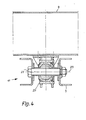
- each individual bearing of the front bearing pair consists of a conical rubber-metal element 13, which is composed of an outer conical metal shell 14, an inner conical base 15 and the rubber element 16 with hard suspension vulcanized on between both parts.
- the rubber metal element 13 is fastened to the bracket 12 via the base 15.
- two bell-type bearing caps 17 are attached, which rest on the outer metal shells of the rubber-metal elements 13, the bearing caps 17 and the metal shell 14 having the same cone angle because of an exact guidance of the platform in the horizontal vehicle plane.
- connection of the bearing cover 17 or the platform with the rubber-metal element 13 takes place via a screw bolt 18 which is inserted centrally through openings in the parts 14 to 17 and on the downwardly projecting length of which a rubber ring spring 19 is pushed, which is pushed against the by means of a nut 20 Underside of the metal base 15 is pressed with a low preload.
- a screw bolt 18 which is inserted centrally through openings in the parts 14 to 17 and on the downwardly projecting length of which a rubber ring spring 19 is pushed, which is pushed against the by means of a nut 20 Underside of the metal base 15 is pressed with a low preload.
- a rubber ring springs instead of the rubber ring springs, other types of springs, e.g. Disc springs are installed.
- the rubber ring spring 19 has a soft spring characteristic with long spring travel, whereby the bearing cap 17 can lift off the bearing shell 14 in the event of twisting of the frame at the bearing point that is subject to tension, so that squeezing of the platform floor is largely avoided.
- the individual bearing point of the middle bearing point pair 10 consists, according to FIG. 3, of a rubber joint bearing 21 and 22 fastened to the platform floor 5 and to the subframe 4, both of which by one on the inside and one on the outside side of the subframe 4 arranged tab 23 and 24 are interconnected.
- the axes of rotation of the spherical bearings 21 and 22 run in the transverse direction of the vehicle.
- the rear bearing 11 consists of a single rubber joint bearing 27 arranged between the platform floor 5 and the subframe 4, the axis of rotation 25 of which lies in the longitudinal direction of the vehicle.
- the inner part of the bearing is screwed onto the subframe 4 via a screw bolt 26 and the outer part onto the central tube 7.
Landscapes
- Engineering & Computer Science (AREA)
- Mechanical Engineering (AREA)
- Chemical & Material Sciences (AREA)
- Combustion & Propulsion (AREA)
- Transportation (AREA)
- Body Structure For Vehicles (AREA)
Claims (9)
Applications Claiming Priority (2)
| Application Number | Priority Date | Filing Date | Title |
|---|---|---|---|
| DE19792911722 DE2911722A1 (de) | 1979-03-24 | 1979-03-24 | Vorrichtung zum elastischen abstuetzen eines verwindungssteifen aufbaues auf einem verwindungsweichen fahrgestellrahmen von kraftfahrzeugen |
| DE2911722 | 1979-03-24 |
Publications (2)
| Publication Number | Publication Date |
|---|---|
| EP0016469A1 EP0016469A1 (fr) | 1980-10-01 |
| EP0016469B1 true EP0016469B1 (fr) | 1983-01-12 |
Family
ID=6066382
Family Applications (1)
| Application Number | Title | Priority Date | Filing Date |
|---|---|---|---|
| EP80101500A Expired EP0016469B1 (fr) | 1979-03-24 | 1980-03-21 | Dispositif de montage élastique d'une superstructure rigide sur un châssis déformable de véhicule |
Country Status (2)
| Country | Link |
|---|---|
| EP (1) | EP0016469B1 (fr) |
| DE (2) | DE2911722A1 (fr) |
Families Citing this family (12)
| Publication number | Priority date | Publication date | Assignee | Title |
|---|---|---|---|---|
| DE2949232A1 (de) * | 1979-12-07 | 1981-06-11 | Magirus-Deutz Ag, 7900 Ulm | Elastische lagerung einer verwindungsarmen pritsche auf einem verwindungsweichen fahrzeugrahmen |
| ES8608426A1 (es) * | 1984-06-26 | 1986-07-16 | Matra Werke Gmbh | Vehiculo multieje con un chasis poco tendente a torsion |
| DE3423544A1 (de) * | 1984-06-26 | 1986-01-02 | Matra-Werke GmbH, 6000 Frankfurt | Kraftfahrzeug mit einem kastenaufbau und einem kran |
| DE3423545A1 (de) * | 1984-06-26 | 1986-01-09 | Matra-Werke GmbH, 6000 Frankfurt | Mehrachsiges kraftfahrzeug mit einem aufbau |
| FR2674926B1 (fr) * | 1991-04-08 | 1993-07-30 | Hutchinson | Dispositif elastique de support d'une structure de vehicule sur une structure de suspension. |
| ZA933714B (en) * | 1992-06-24 | 1994-01-03 | Alusuisse Lonza Services Ag | Sound proofing and vibration dampening elastic connecting element |
| DE10106495C2 (de) * | 2001-02-13 | 2003-08-07 | Crossmobil Gmbh | Lastfahrzeug |
| AU2007201785B2 (en) * | 2007-04-23 | 2009-05-07 | Wayne Peter Jackson | A Vehicle Tray Mounting System |
| GB2458122A (en) * | 2008-03-04 | 2009-09-09 | Agco Sa | Cab mounting mechanism. |
| SK842009A3 (sk) * | 2009-11-08 | 2011-06-06 | Július Chrobák | Upevnenie automobilovej nadstavby |
| DE102019124460A1 (de) | 2019-09-11 | 2021-03-11 | Rheinmetall MAN Military Vehicles Österreich GesmbH | Fahrgestell und Nutzfahrzeug |
| CN111924014A (zh) * | 2020-08-18 | 2020-11-13 | 南京英德利汽车有限公司 | 一种车辆改装用柔性连接件及其连接结构 |
Family Cites Families (11)
| Publication number | Priority date | Publication date | Assignee | Title |
|---|---|---|---|---|
| FR663652A (fr) * | 1928-11-08 | 1929-08-23 | Châssis de véhicule | |
| DE831952C (de) * | 1949-05-07 | 1952-02-18 | Daimler Benz Ag | Elastische Lagerung, insbesondere einer Fahrzeugkarosserie auf dem Fahrgestellrahmen |
| FR1038576A (fr) * | 1951-02-21 | 1953-09-30 | Dispositif perfectionné d'attache des carrosseries aux longerons des châssis des véhicules automobiles, remorques ou semi-remorques | |
| DE1290830B (de) * | 1956-02-18 | 1969-03-13 | Maschf Augsburg Nuernberg Ag | Befestigung des Fahrerhauses von Lastkraftwagen am Fahrzeugrahmen |
| DE1216127B (de) * | 1956-10-05 | 1966-05-05 | Maschf Augsburg Nuernberg Ag | Befestigung des Fahrerhauses von Kraftfahrzeugen am Fahrzeugrahmen |
| DE1109539B (de) * | 1958-09-11 | 1961-06-22 | Daimler Benz Ag | Fahrerhausbefestigung, insbesondere fuer Nutzkraftfahrzeuge |
| NL126138C (fr) * | 1962-03-10 | |||
| DE1917937A1 (de) * | 1969-04-09 | 1970-10-15 | Clouth Gummiwerke Ag | Abfederung fuer Fahrzeuge |
| FR2094359A5 (fr) * | 1970-06-18 | 1972-02-04 | Chausson Usines Sa | |
| DE2345890A1 (de) * | 1973-09-12 | 1975-03-27 | Daimler Benz Ag | Lastkraftwagen mit einem fahrgestellrahmen |
| FR2305644A1 (fr) * | 1975-03-26 | 1976-10-22 | Mitsubishi Motors Corp | Amortisseur de chocs pour vehicule |
-
1979
- 1979-03-24 DE DE19792911722 patent/DE2911722A1/de not_active Withdrawn
-
1980
- 1980-03-21 DE DE8080101500T patent/DE3061570D1/de not_active Expired
- 1980-03-21 EP EP80101500A patent/EP0016469B1/fr not_active Expired
Also Published As
| Publication number | Publication date |
|---|---|
| DE2911722A1 (de) | 1980-10-02 |
| DE3061570D1 (en) | 1983-02-17 |
| EP0016469A1 (fr) | 1980-10-01 |
Similar Documents
| Publication | Publication Date | Title |
|---|---|---|
| DE19521875C2 (de) | Achsaufhängung für Starrachsen in Fahrzeugen | |
| EP0290587B1 (fr) | Suspension indépendante pour un véhicule, particulièrement pour un autobus | |
| DE60008009T2 (de) | Einzelradaufhängung | |
| EP1404536A1 (fr) | Essieu arriere d'un vehicule automobile dote de cinq bras oscillants | |
| DE1430938C3 (de) | Radaufhaengung von Kraftfahrzeugen | |
| EP0016469B1 (fr) | Dispositif de montage élastique d'une superstructure rigide sur un châssis déformable de véhicule | |
| EP0464412B1 (fr) | Suspension pneumatique à bras longitudinaux | |
| EP0352541A1 (fr) | Suspension élastique d'essieu pour véhicules automobiles, notamment pour véhicules utilitaires | |
| DE69613707T2 (de) | Hinterradaufhängung für kraftfahrzeuge | |
| EP1123821B2 (fr) | Suspension à cinq bras pour une roue arrière de véhicule | |
| DE1530490A1 (de) | Doppelachsaufhaengung | |
| EP0167712B1 (fr) | Stabilisateur pour véhicules | |
| DE10055859A1 (de) | Achskonstruktion für nichtangetriebene Fahrzeugachsen | |
| EP0464415B1 (fr) | Suspension à bras longitudinaux pour véhicules à moteur et remorques | |
| DE69304236T2 (de) | Radaufhängungsvorrichtung für einen lenkbaren Vorderradsatz eines Nutzfahrzeuges | |
| DE10011417B4 (de) | Einzelradaufhängung mit radführenden Schräglenkern | |
| DE69325134T2 (de) | Hinterradaufhängung für Kraftfahrzeug mit unabhängigen Rädern | |
| DE3742599A1 (de) | Einrichtung zur hoehenverstellung eines fahrzeugrades | |
| DE2949232A1 (de) | Elastische lagerung einer verwindungsarmen pritsche auf einem verwindungsweichen fahrzeugrahmen | |
| DE1138645B (de) | Hinterradabfederung, insbesondere fuer Kraftfahrzeuge | |
| DE10014878A1 (de) | Mehrlenker-Radaufhängung eines Kraftfahrzeugs | |
| DE3875237T2 (de) | Hintere kraftfahrzeugaufhaengung mit unabhaengigen raedern. | |
| DE3207109C2 (de) | Hinterachse für Kraftfahrzeuge | |
| DE102014200420A1 (de) | Einzelradaufhängung sowie Hinterachsmodul mit Einzelradaufhängungen für ein Fahrzeug und entsprechend ausgestattetes Fahrzeug | |
| DE3928134A1 (de) | Federnde aufhaengung fuer ein einzelrad eines kraftfahrzeugs |
Legal Events
| Date | Code | Title | Description |
|---|---|---|---|
| PUAI | Public reference made under article 153(3) epc to a published international application that has entered the european phase |
Free format text: ORIGINAL CODE: 0009012 |
|
| AK | Designated contracting states |
Designated state(s): DE FR GB IT SE |
|
| 17P | Request for examination filed |
Effective date: 19810307 |
|
| ITF | It: translation for a ep patent filed | ||
| GRAA | (expected) grant |
Free format text: ORIGINAL CODE: 0009210 |
|
| AK | Designated contracting states |
Designated state(s): DE FR GB IT SE |
|
| ET | Fr: translation filed | ||
| REF | Corresponds to: |
Ref document number: 3061570 Country of ref document: DE Date of ref document: 19830217 |
|
| ITPR | It: changes in ownership of a european patent |
Owner name: CAMBIO RAGIONE SOCIALE;IVECO MAGIRUS AG |
|
| RAP2 | Party data changed (patent owner data changed or rights of a patent transferred) |
Owner name: IVECO MAGIRUS AKTIENGESELLSCHAFT |
|
| PGFP | Annual fee paid to national office [announced via postgrant information from national office to epo] |
Ref country code: DE Payment date: 19840127 Year of fee payment: 5 |
|
| PGFP | Annual fee paid to national office [announced via postgrant information from national office to epo] |
Ref country code: FR Payment date: 19840330 Year of fee payment: 5 |
|
| REG | Reference to a national code |
Ref country code: FR Ref legal event code: CD |
|
| PGFP | Annual fee paid to national office [announced via postgrant information from national office to epo] |
Ref country code: SE Payment date: 19840331 Year of fee payment: 5 |
|
| PG25 | Lapsed in a contracting state [announced via postgrant information from national office to epo] |
Ref country code: SE Effective date: 19850322 |
|
| GBPC | Gb: european patent ceased through non-payment of renewal fee | ||
| PG25 | Lapsed in a contracting state [announced via postgrant information from national office to epo] |
Ref country code: FR Free format text: LAPSE BECAUSE OF NON-PAYMENT OF DUE FEES Effective date: 19851129 |
|
| PG25 | Lapsed in a contracting state [announced via postgrant information from national office to epo] |
Ref country code: DE Effective date: 19851203 |
|
| REG | Reference to a national code |
Ref country code: FR Ref legal event code: ST |
|
| PG25 | Lapsed in a contracting state [announced via postgrant information from national office to epo] |
Ref country code: GB Effective date: 19881118 |
|
| EUG | Se: european patent has lapsed |
Ref document number: 80101500.9 Effective date: 19860128 |
|
| PLBE | No opposition filed within time limit |
Free format text: ORIGINAL CODE: 0009261 |
|
| STAA | Information on the status of an ep patent application or granted ep patent |
Free format text: STATUS: NO OPPOSITION FILED WITHIN TIME LIMIT |