EP0016486A1 - Dachkonstruktion für ein Gebäude - Google Patents
Dachkonstruktion für ein Gebäude Download PDFInfo
- Publication number
- EP0016486A1 EP0016486A1 EP19800200172 EP80200172A EP0016486A1 EP 0016486 A1 EP0016486 A1 EP 0016486A1 EP 19800200172 EP19800200172 EP 19800200172 EP 80200172 A EP80200172 A EP 80200172A EP 0016486 A1 EP0016486 A1 EP 0016486A1
- Authority
- EP
- European Patent Office
- Prior art keywords
- roof
- ceiling
- elements
- flanges
- combined
- Prior art date
- Legal status (The legal status is an assumption and is not a legal conclusion. Google has not performed a legal analysis and makes no representation as to the accuracy of the status listed.)
- Ceased
Links
- 239000004568 cement Substances 0.000 claims abstract description 11
- 239000002253 acid Substances 0.000 claims abstract description 8
- 229920000642 polymer Polymers 0.000 claims abstract description 8
- 239000006185 dispersion Substances 0.000 claims abstract description 5
- 239000002245 particle Substances 0.000 claims abstract description 4
- 239000011347 resin Substances 0.000 claims abstract description 4
- 229920005989 resin Polymers 0.000 claims abstract description 4
- 239000003829 resin cement Substances 0.000 claims abstract description 4
- 238000009423 ventilation Methods 0.000 claims description 4
- 239000000178 monomer Substances 0.000 description 5
- VZCYOOQTPOCHFL-OWOJBTEDSA-N Fumaric acid Chemical compound OC(=O)\C=C\C(O)=O VZCYOOQTPOCHFL-OWOJBTEDSA-N 0.000 description 4
- 239000002952 polymeric resin Substances 0.000 description 3
- 229920003002 synthetic resin Polymers 0.000 description 3
- VZCYOOQTPOCHFL-UHFFFAOYSA-N trans-butenedioic acid Natural products OC(=O)C=CC(O)=O VZCYOOQTPOCHFL-UHFFFAOYSA-N 0.000 description 3
- 229920002554 vinyl polymer Polymers 0.000 description 3
- JAHNSTQSQJOJLO-UHFFFAOYSA-N 2-(3-fluorophenyl)-1h-imidazole Chemical compound FC1=CC=CC(C=2NC=CN=2)=C1 JAHNSTQSQJOJLO-UHFFFAOYSA-N 0.000 description 2
- NBIIXXVUZAFLBC-UHFFFAOYSA-N Phosphoric acid Chemical compound OP(O)(O)=O NBIIXXVUZAFLBC-UHFFFAOYSA-N 0.000 description 2
- PPBRXRYQALVLMV-UHFFFAOYSA-N Styrene Chemical compound C=CC1=CC=CC=C1 PPBRXRYQALVLMV-UHFFFAOYSA-N 0.000 description 2
- 150000001735 carboxylic acids Chemical class 0.000 description 2
- 239000001530 fumaric acid Substances 0.000 description 2
- LVHBHZANLOWSRM-UHFFFAOYSA-N methylenebutanedioic acid Natural products OC(=O)CC(=C)C(O)=O LVHBHZANLOWSRM-UHFFFAOYSA-N 0.000 description 2
- 230000035515 penetration Effects 0.000 description 2
- 125000000391 vinyl group Chemical group [H]C([*])=C([H])[H] 0.000 description 2
- XLYOFNOQVPJJNP-UHFFFAOYSA-N water Substances O XLYOFNOQVPJJNP-UHFFFAOYSA-N 0.000 description 2
- SMZOUWXMTYCWNB-UHFFFAOYSA-N 2-(2-methoxy-5-methylphenyl)ethanamine Chemical compound COC1=CC=C(C)C=C1CCN SMZOUWXMTYCWNB-UHFFFAOYSA-N 0.000 description 1
- NIXOWILDQLNWCW-UHFFFAOYSA-N 2-Propenoic acid Natural products OC(=O)C=C NIXOWILDQLNWCW-UHFFFAOYSA-N 0.000 description 1
- NLHHRLWOUZZQLW-UHFFFAOYSA-N Acrylonitrile Chemical compound C=CC#N NLHHRLWOUZZQLW-UHFFFAOYSA-N 0.000 description 1
- VGGSQFUCUMXWEO-UHFFFAOYSA-N Ethene Chemical compound C=C VGGSQFUCUMXWEO-UHFFFAOYSA-N 0.000 description 1
- 239000005977 Ethylene Substances 0.000 description 1
- CERQOIWHTDAKMF-UHFFFAOYSA-N Methacrylic acid Chemical compound CC(=C)C(O)=O CERQOIWHTDAKMF-UHFFFAOYSA-N 0.000 description 1
- VVQNEPGJFQJSBK-UHFFFAOYSA-N Methyl methacrylate Chemical compound COC(=O)C(C)=C VVQNEPGJFQJSBK-UHFFFAOYSA-N 0.000 description 1
- OFOBLEOULBTSOW-UHFFFAOYSA-N Propanedioic acid Natural products OC(=O)CC(O)=O OFOBLEOULBTSOW-UHFFFAOYSA-N 0.000 description 1
- 229910000831 Steel Inorganic materials 0.000 description 1
- XTXRWKRVRITETP-UHFFFAOYSA-N Vinyl acetate Chemical compound CC(=O)OC=C XTXRWKRVRITETP-UHFFFAOYSA-N 0.000 description 1
- BZHJMEDXRYGGRV-UHFFFAOYSA-N Vinyl chloride Chemical compound ClC=C BZHJMEDXRYGGRV-UHFFFAOYSA-N 0.000 description 1
- 150000007513 acids Chemical class 0.000 description 1
- XYLMUPLGERFSHI-UHFFFAOYSA-N alpha-Methylstyrene Chemical compound CC(=C)C1=CC=CC=C1 XYLMUPLGERFSHI-UHFFFAOYSA-N 0.000 description 1
- 239000004411 aluminium Substances 0.000 description 1
- XAGFODPZIPBFFR-UHFFFAOYSA-N aluminium Chemical compound [Al] XAGFODPZIPBFFR-UHFFFAOYSA-N 0.000 description 1
- 229910052782 aluminium Inorganic materials 0.000 description 1
- 229910000147 aluminium phosphate Inorganic materials 0.000 description 1
- 125000000484 butyl group Chemical group [H]C([*])([H])C([H])([H])C([H])([H])C([H])([H])[H] 0.000 description 1
- 239000004035 construction material Substances 0.000 description 1
- LDHQCZJRKDOVOX-NSCUHMNNSA-N crotonic acid Chemical compound C\C=C\C(O)=O LDHQCZJRKDOVOX-NSCUHMNNSA-N 0.000 description 1
- OIWOHHBRDFKZNC-UHFFFAOYSA-N cyclohexyl 2-methylprop-2-enoate Chemical compound CC(=C)C(=O)OC1CCCCC1 OIWOHHBRDFKZNC-UHFFFAOYSA-N 0.000 description 1
- JBSLOWBPDRZSMB-BQYQJAHWSA-N dibutyl (e)-but-2-enedioate Chemical compound CCCCOC(=O)\C=C\C(=O)OCCCC JBSLOWBPDRZSMB-BQYQJAHWSA-N 0.000 description 1
- JBSLOWBPDRZSMB-FPLPWBNLSA-N dibutyl (z)-but-2-enedioate Chemical compound CCCCOC(=O)\C=C/C(=O)OCCCC JBSLOWBPDRZSMB-FPLPWBNLSA-N 0.000 description 1
- 125000001495 ethyl group Chemical group [H]C([H])([H])C([H])([H])* 0.000 description 1
- LNMQRPPRQDGUDR-UHFFFAOYSA-N hexyl prop-2-enoate Chemical compound CCCCCCOC(=O)C=C LNMQRPPRQDGUDR-UHFFFAOYSA-N 0.000 description 1
- VZCYOOQTPOCHFL-UPHRSURJSA-N maleic acid Chemical compound OC(=O)\C=C/C(O)=O VZCYOOQTPOCHFL-UPHRSURJSA-N 0.000 description 1
- 239000011976 maleic acid Substances 0.000 description 1
- 239000000463 material Substances 0.000 description 1
- XJRBAMWJDBPFIM-UHFFFAOYSA-N methyl vinyl ether Chemical compound COC=C XJRBAMWJDBPFIM-UHFFFAOYSA-N 0.000 description 1
- 230000004048 modification Effects 0.000 description 1
- 238000012986 modification Methods 0.000 description 1
- 239000004570 mortar (masonry) Substances 0.000 description 1
- 230000003647 oxidation Effects 0.000 description 1
- 238000007254 oxidation reaction Methods 0.000 description 1
- 239000004033 plastic Substances 0.000 description 1
- 229920003023 plastic Polymers 0.000 description 1
- QQONPFPTGQHPMA-UHFFFAOYSA-N propylene Natural products CC=C QQONPFPTGQHPMA-UHFFFAOYSA-N 0.000 description 1
- 125000004805 propylene group Chemical group [H]C([H])([H])C([H])([*:1])C([H])([H])[*:2] 0.000 description 1
- 239000002990 reinforced plastic Substances 0.000 description 1
- 238000007127 saponification reaction Methods 0.000 description 1
- 239000010959 steel Substances 0.000 description 1
- LDHQCZJRKDOVOX-UHFFFAOYSA-N trans-crotonic acid Natural products CC=CC(O)=O LDHQCZJRKDOVOX-UHFFFAOYSA-N 0.000 description 1
- 239000002023 wood Substances 0.000 description 1
Images

Classifications
-
- E—FIXED CONSTRUCTIONS
- E04—BUILDING
- E04B—GENERAL BUILDING CONSTRUCTIONS; WALLS, e.g. PARTITIONS; ROOFS; FLOORS; CEILINGS; INSULATION OR OTHER PROTECTION OF BUILDINGS
- E04B1/00—Constructions in general; Structures which are not restricted either to walls, e.g. partitions, or floors or ceilings or roofs
- E04B1/343—Structures characterised by movable, separable, or collapsible parts, e.g. for transport
- E04B1/344—Structures characterised by movable, separable, or collapsible parts, e.g. for transport with hinged parts
- E04B1/3445—Structures characterised by movable, separable, or collapsible parts, e.g. for transport with hinged parts foldable in a flat stack of parallel panels
- E04B1/3447—Portal- or saddle-shaped structures
-
- E—FIXED CONSTRUCTIONS
- E04—BUILDING
- E04B—GENERAL BUILDING CONSTRUCTIONS; WALLS, e.g. PARTITIONS; ROOFS; FLOORS; CEILINGS; INSULATION OR OTHER PROTECTION OF BUILDINGS
- E04B7/00—Roofs; Roof construction with regard to insulation
- E04B7/02—Roofs; Roof construction with regard to insulation with plane sloping surfaces, e.g. saddle roofs
- E04B7/026—Roofs; Roof construction with regard to insulation with plane sloping surfaces, e.g. saddle roofs consisting of prefabricated modules, e.g. box-like or cell-like units
Definitions
- the invention relates to a combined sloping roof-ceiling, built up of pre-fabricated elements.
- a roof-ceiling system which is also built up of pre-fabricated elements.
- the drawback of this system is that the dimensions of that ceiling and therefore also of the roof are entirely determined by the dimensions of the substructure, while, moreover, mounting of the ceiling, which- is placed between the side-walls of the dwelling, requires correct spacing of the side-walls.
- mounting is laborious owing to the large dimensions, takes much time, and, in addition, requires trained craftsmen.
- the purpose of the invention is to provide a roof-ceiling combination built up of prefabricated roof-ceiling segments placed side by side and coupled to each other, which can be mounted independently of the dimensions of the substructure in a very short time, and which form a very stable whole.
- the dimensions of the elements are less large, which makes transport and mounting easier and, moreover, permits of unlimited expansion of the dwelling in two directions. Mounting is very simple, moreover, and no additional roofing like tiles or slates etc. is needed.
- roof-ceiling being built up of roof-ceiling segments coupled to each other side by side, which segments consist of an oblong section, as ceiling element, of a substantially L-orU-shaped profile, and two oblong roof elements of practically the same width as the ceiling element, also of a substantially L--or U-shaped profile as roof elements, which near the two ends are attached to the flange or to both flanges of the ceiling element and which roof elements are rigidly coupled to each other at the ridge when mounted.
- oblong is meant that, for instance, the ratio of the length to the width is 4 : 1 to 8 : 1.
- the flange of the L-shaped element is understood the short leg of the L-shape.
- flange or flanges of the ceiling elements are turned upward. Covering of the flanges of the roof elements, which are placed against each other, is preferably done by means of a cover profile, placed over the edges to prevent penetration of rain water.
- the adjacent edges of the roof elements of several elements, when mounted, are preferably covered at the ridge by a ridge profile. In the system according to the invention, the overhang of the roof elements, and thereby also the roof pitch, can be easily varied.
- the ceiling and roof elements may have been made of a variety of materials, such as steel, aluminium, plastic, or glassfibre- reinforced plastic and in particular fibre-reinforced cement, in which preferably has also been taken up a resin dispersion of a polymer which contains acid'radicals and has an average particle size between 0.05 and 5 microns, the setting mass having a water-cement ratio between 0.2 and 0.5, while the resin-cement weight ratio, is between 0.02 and 0.4.
- materials such as steel, aluminium, plastic, or glassfibre- reinforced plastic and in particular fibre-reinforced cement, in which preferably has also been taken up a resin dispersion of a polymer which contains acid'radicals and has an average particle size between 0.05 and 5 microns, the setting mass having a water-cement ratio between 0.2 and 0.5, while the resin-cement weight ratio, is between 0.02 and 0.4.
- the width of the roof and ceiling elements may vary between wide limits, e.g. from 15 to 240 cm, the height of the upright edges being 5 to 60 cm. Preferably, the width is 30-120 cm and the height of the flanges 10-40 cm.
- the bodies of the roof elements have a step-shaped profile, for reasons of strength as well as aesthetics.
- the roof elements may advantageously be provided with a raised edge, which is in particular higher than the upright flange or flanges.
- the length of the ceiling elements may vary from 2 to 12 m, in particular from 3-8 m. In attaching the roof elements to the ends of the ceiling elements, it is possible to leave a clearance between the bodies of the two-elements.
- Ventilation air can flow in through this clearance, leaving the roof again at the ridge.
- the ridge profile is mounted with a clearance over the slightly spaced end edges of the roof elements.
- continuous ventilation between roof and ceiling is obtained.
- the combined roof-ceiling according to the invention is mounted very simply, is very stable and is independent of the substructure. Positioning of the interior walls of the substructure is completely free; as regards the positioning of the outer walls, there is a high degree of freedom.
- the ceiling is rigid and can be walked on, so that the room above the ceiling can be made fit to live in.
- the roof-ceiling is cheap and, moreover, wood-substituting. This is of particular importance for countries where wood as a construction material is scarce.
- Fig. 1 shows a diagrammatic representation of a U-shaped ceiling element of fibre-reinforced cement to which has been added a resin dispersion consisting of a dispersion of a polymer which contains acid radicals and has an average particle size between 0.05 and 5 microns, the water-setting mass having a water-cement ratio between 0.2 and 0.5, while the resin-cement weight ratio is between 0.02 and 0.4.
- the processability of the mortars used is excellent, in spite of the lower water-cement factor and the presence of the acid radicals.
- polymer resins prepared from monomers containing vinyl radicals should contain acid radicals such as phosphoric acid or sulphoric acid radicals.
- acid radicals such as phosphoric acid or sulphoric acid radicals.
- carboxylic radicals may come from built-in mono-unsaturated acids, such as acrylic acid, methacrylic acid, fumaric acid, itaconic acid, crotonic acid or semi-esters of maleic acid, fumaric acid or itaconic acid; they may also have been grafted onto the polymer. Further, they may have been formed through modification, in particular through oxidation or saponification, of certain polymers.
- carboxylic acids from monomers with one free valency, containing one or more carboxylic radicals and polymerized into the polymeric resin.
- these monomers are preferably present in a quantity of 2.5 to 30 % by wt. relative to the polymer. Very good results are obtained if the quantity of unsaturated monomer containing carboxylic acids amounts to 5 to 25 % by wt., in particular from 10 to 20 % by wt.
- the polymers consist of vinyl monomers, styrene, a-methyl styrene, vinyl chloride, cyclohexyl methacrylate, acrylonitrile, vinyl acetate, vinyl versatate, methyl methacrylate, ethyl, butyl and hexylacrylate, dibutyl fumarate, or dibutyl maleate, methyl vinyl ether, ethylene and propylene.
- the water-cement factor between 0.2 and 0.4.
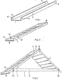
- a ceiling element of a U-shaped cross-section consists of the body 1 and the flanges 2 and 3, the ends of which have been provided with holes 4, through which pivoting pins can be stuck.
- Fig. 2 represents a roof element of a U-shaped cross-section with a step-shaped profile.
- 5 indicates the body and 6 and 7 the flanges.
- the element has a raised edge 8.
- Fig. 3 shows a combined roof-ceiling segment.
- Ceiling elements of a U-shaped cross-section are attached to the substructure (not shown).
- the roof segments 5, 6, 7 are pivoted to the ceiling elements by means of pins 10 which pass through the holes 4 and 12 of the ceiling elements and the roof elements, respectively. Subsequently, the roof segments are swung up till the upright edges 8 meet. These edges 8 are coupled to each other by means of pins 11.
- a ridge profile 9 is placed over the upright edges 8 to prevent penetration of rain water.
- Fig. 4 shows two coupled roof-ceiling segments, one behind the other. Over the abutting flanges 6, 7 of the roof elements of U-shaped cross-section, a cover profile 13 has been placed for the same purpose as the ridge profile 9.
Landscapes
- Engineering & Computer Science (AREA)
- Architecture (AREA)
- Physics & Mathematics (AREA)
- Electromagnetism (AREA)
- Civil Engineering (AREA)
- Structural Engineering (AREA)
- Roof Covering Using Slabs Or Stiff Sheets (AREA)
Applications Claiming Priority (2)
| Application Number | Priority Date | Filing Date | Title |
|---|---|---|---|
| NL7901624A NL7901624A (nl) | 1979-03-01 | 1979-03-01 | Gecombineerd dak-plafond. |
| NL7901624 | 1979-03-01 |
Publications (1)
| Publication Number | Publication Date |
|---|---|
| EP0016486A1 true EP0016486A1 (de) | 1980-10-01 |
Family
ID=19832714
Family Applications (1)
| Application Number | Title | Priority Date | Filing Date |
|---|---|---|---|
| EP19800200172 Ceased EP0016486A1 (de) | 1979-03-01 | 1980-02-28 | Dachkonstruktion für ein Gebäude |
Country Status (3)
| Country | Link |
|---|---|
| EP (1) | EP0016486A1 (de) |
| BR (1) | BR8001230A (de) |
| NL (1) | NL7901624A (de) |
Cited By (3)
| Publication number | Priority date | Publication date | Assignee | Title |
|---|---|---|---|---|
| AT392112B (de) * | 1986-02-04 | 1991-01-25 | Rauch Alfred | Fertigdachkonstruktion |
| EP0895713A1 (de) * | 1997-08-08 | 1999-02-10 | Eva Dilys Bruno | Verbesserungen an Bogenstrukturen |
| GB2355274A (en) * | 1999-10-13 | 2001-04-18 | Clive Braybrooke | Roofing with prefabricated panels |
Families Citing this family (1)
| Publication number | Priority date | Publication date | Assignee | Title |
|---|---|---|---|---|
| JP7797033B2 (ja) * | 2021-10-28 | 2026-01-13 | 合同会社無限 | プレキャストコンクリート製の屋根パネル及び屋根パネルにより構成される屋根並びに屋根を含む立体構築物 |
Citations (5)
| Publication number | Priority date | Publication date | Assignee | Title |
|---|---|---|---|---|
| FR870332A (fr) * | 1940-10-31 | 1942-03-09 | Applic Des Procedes Enklay Cim | Perfectionnements aux toitures |
| GB723675A (en) * | 1953-08-05 | 1955-02-09 | Dow Mac Products Ltd | Improvements in or relating to roofs |
| FR1182260A (fr) * | 1957-04-04 | 1959-06-24 | Nouvelle toiture perfectionnée | |
| FR2381872A1 (fr) * | 1977-02-24 | 1978-09-22 | Poyet Jean Charles | Procede de construction de batiments |
| FR2381876A1 (fr) * | 1977-02-24 | 1978-09-22 | Rougier & Fils Sa | Toiture et son procede de montage |
-
1979
- 1979-03-01 NL NL7901624A patent/NL7901624A/nl not_active Application Discontinuation
-
1980
- 1980-02-28 EP EP19800200172 patent/EP0016486A1/de not_active Ceased
- 1980-02-29 BR BR8001230A patent/BR8001230A/pt unknown
Patent Citations (5)
| Publication number | Priority date | Publication date | Assignee | Title |
|---|---|---|---|---|
| FR870332A (fr) * | 1940-10-31 | 1942-03-09 | Applic Des Procedes Enklay Cim | Perfectionnements aux toitures |
| GB723675A (en) * | 1953-08-05 | 1955-02-09 | Dow Mac Products Ltd | Improvements in or relating to roofs |
| FR1182260A (fr) * | 1957-04-04 | 1959-06-24 | Nouvelle toiture perfectionnée | |
| FR2381872A1 (fr) * | 1977-02-24 | 1978-09-22 | Poyet Jean Charles | Procede de construction de batiments |
| FR2381876A1 (fr) * | 1977-02-24 | 1978-09-22 | Rougier & Fils Sa | Toiture et son procede de montage |
Cited By (3)
| Publication number | Priority date | Publication date | Assignee | Title |
|---|---|---|---|---|
| AT392112B (de) * | 1986-02-04 | 1991-01-25 | Rauch Alfred | Fertigdachkonstruktion |
| EP0895713A1 (de) * | 1997-08-08 | 1999-02-10 | Eva Dilys Bruno | Verbesserungen an Bogenstrukturen |
| GB2355274A (en) * | 1999-10-13 | 2001-04-18 | Clive Braybrooke | Roofing with prefabricated panels |
Also Published As
| Publication number | Publication date |
|---|---|
| BR8001230A (pt) | 1980-11-04 |
| NL7901624A (nl) | 1980-09-03 |
Similar Documents
| Publication | Publication Date | Title |
|---|---|---|
| US9121184B2 (en) | Pultruded trim members | |
| US6386972B1 (en) | Vent apparatus | |
| US5358006A (en) | Adjustable downspout extension assembly | |
| US6185891B1 (en) | Hurricane resistant foam-concrete structural composite | |
| US20010022055A1 (en) | Plastic roof tiles | |
| JP2002502470A (ja) | ベニヤ仕上げされた建物用の通気ストリップ | |
| US6935075B2 (en) | Triangular stackable building wall module and method | |
| US3347006A (en) | Swimming pool and coping structure therefor | |
| US3248827A (en) | Integral rain gutter and attaching means therefor | |
| US8756888B2 (en) | Modular building panel and duct system | |
| US20080127587A1 (en) | Exterior roofing surface comprised of foam and cement coating | |
| EP0016486A1 (de) | Dachkonstruktion für ein Gebäude | |
| US5392584A (en) | Method and apparatus for producing roof tile | |
| US20220042323A1 (en) | Deck drainage systems | |
| US6706366B2 (en) | Curved roofing tile structure | |
| US5577354A (en) | Eave trim system | |
| US20070066216A1 (en) | Exterior roofing surface comprised of foam | |
| WO2012059757A2 (en) | Improved cladding system | |
| CN213297024U (zh) | 一种装配式隔墙龙骨型材的踢脚线 | |
| EP0015899B1 (de) | Verbesserte zusammensetzung und anwendungsverfahren | |
| CN217711090U (zh) | 一种组合式木屋 | |
| AU606480B2 (en) | Flexi tray | |
| JP3972981B2 (ja) | 通気止縁 | |
| US860682A (en) | Building construction material. | |
| JPH0421370Y2 (de) |
Legal Events
| Date | Code | Title | Description |
|---|---|---|---|
| PUAI | Public reference made under article 153(3) epc to a published international application that has entered the european phase |
Free format text: ORIGINAL CODE: 0009012 |
|
| AK | Designated contracting states |
Designated state(s): AT BE CH DE FR GB IT LU NL SE |
|
| 17P | Request for examination filed |
Effective date: 19810313 |
|
| STAA | Information on the status of an ep patent application or granted ep patent |
Free format text: STATUS: THE APPLICATION HAS BEEN REFUSED |
|
| 18R | Application refused |
Effective date: 19840103 |
|
| RIN1 | Information on inventor provided before grant (corrected) |
Inventor name: VAN DEN BERG, MARINUS HUBERTUS NICOLAAS |