EP0016542A2 - Kombination einer elektrodenlosen Entladungslampe mit einem Radiofrequenz-Oszillatorkreis - Google Patents
Kombination einer elektrodenlosen Entladungslampe mit einem Radiofrequenz-Oszillatorkreis Download PDFInfo
- Publication number
- EP0016542A2 EP0016542A2 EP80300500A EP80300500A EP0016542A2 EP 0016542 A2 EP0016542 A2 EP 0016542A2 EP 80300500 A EP80300500 A EP 80300500A EP 80300500 A EP80300500 A EP 80300500A EP 0016542 A2 EP0016542 A2 EP 0016542A2
- Authority
- EP
- European Patent Office
- Prior art keywords
- circuit
- core
- radio
- frequency
- oscillator
- Prior art date
- Legal status (The legal status is an assumption and is not a legal conclusion. Google has not performed a legal analysis and makes no representation as to the accuracy of the status listed.)
- Granted
Links
Images



Classifications
-
- H—ELECTRICITY
- H05—ELECTRIC TECHNIQUES NOT OTHERWISE PROVIDED FOR
- H05B—ELECTRIC HEATING; ELECTRIC LIGHT SOURCES NOT OTHERWISE PROVIDED FOR; CIRCUIT ARRANGEMENTS FOR ELECTRIC LIGHT SOURCES, IN GENERAL
- H05B41/00—Circuit arrangements or apparatus for igniting or operating discharge lamps
- H05B41/14—Circuit arrangements
- H05B41/26—Circuit arrangements in which the lamp is fed by power derived from DC by means of a converter, e.g. by high-voltage DC
- H05B41/28—Circuit arrangements in which the lamp is fed by power derived from DC by means of a converter, e.g. by high-voltage DC using static converters
- H05B41/2806—Circuit arrangements in which the lamp is fed by power derived from DC by means of a converter, e.g. by high-voltage DC using static converters with semiconductor devices and specially adapted for lamps without electrodes in the vessel, e.g. surface discharge lamps, electrodeless discharge lamps
-
- H—ELECTRICITY
- H01—ELECTRIC ELEMENTS
- H01J—ELECTRIC DISCHARGE TUBES OR DISCHARGE LAMPS
- H01J65/00—Lamps without any electrode inside the vessel; Lamps with at least one main electrode outside the vessel
- H01J65/04—Lamps in which a gas filling is excited to luminesce by an external electromagnetic field or by external corpuscular radiation, e.g. for indicating plasma display panels
- H01J65/042—Lamps in which a gas filling is excited to luminesce by an external electromagnetic field or by external corpuscular radiation, e.g. for indicating plasma display panels by an external electromagnetic field
- H01J65/048—Lamps in which a gas filling is excited to luminesce by an external electromagnetic field or by external corpuscular radiation, e.g. for indicating plasma display panels by an external electromagnetic field the field being produced by using an excitation coil
-
- H—ELECTRICITY
- H05—ELECTRIC TECHNIQUES NOT OTHERWISE PROVIDED FOR
- H05B—ELECTRIC HEATING; ELECTRIC LIGHT SOURCES NOT OTHERWISE PROVIDED FOR; CIRCUIT ARRANGEMENTS FOR ELECTRIC LIGHT SOURCES, IN GENERAL
- H05B41/00—Circuit arrangements or apparatus for igniting or operating discharge lamps
- H05B41/14—Circuit arrangements
- H05B41/24—Circuit arrangements in which the lamp is fed by high frequency AC, or with separate oscillator frequency
-
- Y—GENERAL TAGGING OF NEW TECHNOLOGICAL DEVELOPMENTS; GENERAL TAGGING OF CROSS-SECTIONAL TECHNOLOGIES SPANNING OVER SEVERAL SECTIONS OF THE IPC; TECHNICAL SUBJECTS COVERED BY FORMER USPC CROSS-REFERENCE ART COLLECTIONS [XRACs] AND DIGESTS
- Y02—TECHNOLOGIES OR APPLICATIONS FOR MITIGATION OR ADAPTATION AGAINST CLIMATE CHANGE
- Y02B—CLIMATE CHANGE MITIGATION TECHNOLOGIES RELATED TO BUILDINGS, e.g. HOUSING, HOUSE APPLIANCES OR RELATED END-USER APPLICATIONS
- Y02B20/00—Energy efficient lighting technologies, e.g. halogen lamps or gas discharge lamps
Definitions
- This invention generally relates to high frequency electrodeless lamps and, more particularly, to such a lamp which is particularly adapted to be operated by a very efficient and compact radio frequency oscillator operating in Class E mode.
- High frequency electrodeless (HFE) lamps have received considerable attention in recent years as a possible replacement for the standard household incandescent lamps which convert electricity into light in a relatively inefficient manner. Fluorescent lamps are efficient converters of electricity into light, but their cumbersome size and need for ballasting has limited their application in the household. HFE lamps, in contrast to the standard fluorescent lamps, can be fabricated in a relatively compact size.
- the self-oscillatory circuits used to energize the lamp operate in a Class A, B, or C mode, with Class B or C being preferred.
- the present invention resides in a combination of an electrodeless discharge device designed to operate with a rated power consumption when energized with predetermined radio frequency energy as generated by a radio-frequency power source, said radio-frequency power source having an output portion comprising a tuned circuit having a resonant frequency which approximates said predetermined radio frequency at which said device is to be operated, said device comprising:
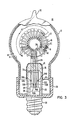
- the device or lamp 10 generally comprises a sealed light-transmitting globular-shaped envelope 12 of predetermined dimensions and enclosing a discharge-sustaining medium such as a few torrs of argon and a small amount of mercury 14, similar to conventional fluorescent lamps.
- a discharge-sustaining medium such as a few torrs of argon and a small amount of mercury 14, similar to conventional fluorescent lamps.
- Carried on the internal surface of the envelope is a layer 16 comprising luminescent phosphor material.
- a core 18 which principally comprises magnetic material of high permeability and having a looped configuration of predetermined dimensions.
- the core has a toroidal configuration and in accordance with the improvement disclosed in the heretofore referenced copending application S.N.
- the core preferably includes a narrow gap 20 comprising low-permeability substance such as mica traversing the cross section of the core.
- a winding 22 having a predetermined number of turns is wrapped about the core and lead-in members 24 connect the winding to the radio frequency power source 25 which comprises an HF drive and oscillator section 26 together with an A.C. to D.C. power supply 28 designed to operate from a 115 volt, A.C. 60 Hz line.
- the radio frequency electromagnetic fields set up through and about the core and within the envelope excite the discharge-sustaining medium to emit short wavelength radiations which in turn excite the phosphor layer to emit visible radiations which pass through the envelope.
- the ferrite core can be considered, electrically, as a transformer with "N" turns of winding 22 on its primary and one turn on its secondary, namely, the discharge, loaded by the equivalent lamp resistance R L .
- Fig. 2A shows this equivalent circuit with the lamp voltage, V L also indicated and Fig. 2B shows a further simplification of this equivalent circuit.
- lamp load is reflected in the coil 22 as approximately N 2 R L ohms and V c equals N V L .
- the practical lamp 10 comprises a sealed light-transmitting globular or pear- shaped envelope 12 of predetermined dimensions.
- the envelope 12 has a height of 6 inches and an outer diameter of 4 inches.
- the envelope 12 is evacuated via the tip 30 at the top thereof and is provided with a discharge-sustaining filling comprising 1.5 torrs of argon and a small charge of mercury 14.
- a layer comprising phosphor material 16 is carried on the interior surface of the envelope and as a specific example, any of the standard halophosphates can be used.
- a three component blend of rare-earth activated phosphors can be used and such a phosphor mixture is disclosed in U.S. Patent No. 3,937,998, dated February 10, 1976 to Verstegen et al.
- a core 18, such as previously described, is operatively, positioned within the envelope 12 and the core principally comprises magnetic material of high permeability and having a looped configuration of predetermined dimensions and cross sectional area, such as previously described in detail.
- the core has a toroidal configuration for convenience of manufacturing, but this configuration can be varied considerably.
- the core also includes a narrow gap 20 which traverses the cross section of the core and a power winding 22 of twenty-two turns is wrapped about the core 18.
- the toroidal core has an outer diameter of 6.096 cm, an inner diameter of 3.556 cm, and a thickness of 1.27 cm.
- the mica gap 20, if included, has a thickness of 0.015 cm.
- the preferred principal material comprising the core 18 is ferrite, although other magnetic materials can be substituted therefor.
- ferrite is any of several compounds formed usually by treating hydrated ferric oxide with an alkali or by heating ferric oxide with a metallic oxide and regarded in some cases as spinels such as NaFe0 2 or ZnFe204.
- the ferrite core specifically considered hereinbefore is marketed as the 8000 Series by Indiana General, a Division of Electronic Memories & Magnetics Corp., Keasbey, NJ and is commercially available in a form which is not provided with the gap as described hereinbefore.
- Such ferrites are normally prepared with a sintering technique.
- the ferrite has a high permeability such as 5,000 and a low electrical resistivity such as 100 ohm-cm. With the gap 20, as described, the effective permeability decreases to 806.8.
- Power lead-in members 24 connect the winding 22 to the radio frequency power source 25 comprising the combined driver 26 and A.C. to D.C. power supply 28 (shown in block form) and positioned within the elongated neck portion 32 of the lamp 10.
- the core 18 comprises a part of the tuned circuit output portion for the radio frequency power source.
- Feed-back signal lead members 33 connect a feed-back winding 34, carried on the core 18, to the radio frequency power source, as described in detail hereinafter.
- the feed-back winding 34 has twenty-two turns.
- the lamp 10 is of generally conventional construction and the four leads 24 and 33 to the coil 18 are sealed through a stem 35 to connect to the power source 25 within the elongated stem and neck, which in turn connects to a conventional screw type base 36 which is affixed to the lamp neck by means of a base adaptor member 38 formed of suitable plastic such as phenolic resin.
- the phosphor material is also coated over the core 18 for most efficient utilization of the 254nm radiations generated by the low-pressure mercury discharge.
- the operation of the lamp 10 is initiated by means of an additional winding 40 comprising a relatively large number of turns carried on the core 18 and the winding 40 terminates in end portions 42 spaced apart a predetermined distance within the envelope 12.
- the additional winding 40 when the tuned circuit is initially energized, the additional winding 40 has generated between the spaced end portions 42 a relatively high voltage and the capacitive coupling therebetween ionizes the discharge-sustaining medium within the envelope 12 to initiate the operation of the device.
- the winding 40 in effect is out of the circuit.
- the winding 40 comprises eighty- eight turns and the end portions 42 are spaced apart by more than one centimeter, and example being two cm.
- the winding 22 can be provided with a layer 46 of a refractory-type inorganic cement such as that marketed by Sauereisen Cement Co., Pittsburgh, PA, and sold under the trademark "Sauereisen Cement", which is a zirconia-based cement.
- a typical thickness for the layer 46 is 0.05 to 0.1 mm.
- Other materials which can be used to coat the ferrite core to insulate the same from the winding are a devitrifying glass such as that marketed by Corning Glass Co. under the trademark "Pyroceram”.
- the winding 22 can be provided with a layer of glass or fiberglass insulation thereabout.
- the power source 25 has power output terminals 48A and 48B which are connected. to the power input terminals 50A and 50B of the device 10 for connection to the power winding 22 of the device 10.
- the power source 25 has feed-back signal input terminals 52A and 52B which are connected to feed- back signal output terminals 54A and 54B on the device 10 for connection to the feed-back winding 34 carried on the core 18.
- Class D and Class E circuits which are potentially more efficient than the Class B or C types and have good power output capability. Since these circuits operate in a switching mode action, they are less subject to changes in the transistor drive parameters and are thus more readily reproducible. While the performance of Class D circuits is good, they require more components than a Class E circuit and also require two center tapped transformers. Since compactness of circuit design is an objective for the present type lamps, Class E circuits are much preferred.
- a Class B circuit can operate at about 78.5% efficiency
- a Class C circuit with 120° angle of flow can operate at a maximum efficiency of 87%
- a Class E circuit with a switching time for the transistor of 0.4 microsecond can operate with a maximum circuit efficiency of about 98% wherein efficiency is defined as A.C. power out times 100% divided by D.C. power in.
- Fig. 4 shows a basic Class E type circuit of the prior art.
- Cl and C2 are load network capacitors, L2 is a load network inductor and Ll is required to pass the D.C. power to the switching transistor.
- Base drive to the transistor is in the form of square waves.
- the transistor used with the circuit is so selected that the collector current fall time is relatively short.
- the collector current fall time should be shorter than about one microsecond and preferably less than about 0.5 microsecond.
- C 2 can be removed from the circuit and this provides a path for the D.C. supply through the load R and load network inductor L 2 , which in turn permits L l , as shown in Fig. 4, to be removed from the circuit since it is no longer required to pass D.C. to the transistor.
- reduction of Q L2 to a value as indicated also reduces the value of L 2 so that the circuit can be further compacted.
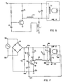
- the circuit can be made self-oscillatory by feed-back of the output voltage, in suitable phase, to the base input of the transistor and such a modified circuit is shown in Fig. 6 wherein a transformer T provides the feed-back signal to the base of the transistor through a phase-controlling capacitor C f .
- the final circuit design is shown in Fig. 7 and comprises circuit input terminals 56A and 56B which are adapted to be connected to a source of A.C. energizing potential, such as 115 VAC, 60 Hz, and circuit power output terminals 48A and 48B adapted for connection to the power input terminals 50A and 50B of the device 10.
- a source of A.C. energizing potential such as 115 VAC, 60 Hz
- circuit power output terminals 48A and 48B adapted for connection to the power input terminals 50A and 50B of the device 10.
- these connections are permanent.
- a rectifier means 58 is connected across the circuit input terminals 56A and 56B for rectifying the A.C. energy to provide across two D.C. output terminals 60A and 60B, a D.C. potential of predetermined value, such as 160 V.
- the full wave diode rectifier 58 incorporates a bridge rectifier type VE48 (Varo Semiconductor, Inc.) and the value of the filter capacitor C is 47 microfarads.
- a transistor means 62 provides a radio frequency oscillation and has a base terminal 64, a collector terminal 66 and an emitter terminal 68 and as an example, this transistor is a type MJE 13003 (Motorola) having a collector current fall time of approximately 0.4 microsecond.
- the base terminal 64 of transistor 62 connects through a resistor R B of predetermined value to the more positive output terminal 60A of the rectifier 58 and also to power output terminal 48A.
- the purpose of the resistor R B is to ensure that the transistor will turn on and as a specific example, it has a value of 47K ohms.
- a load network capacitor Cl having predetermined reactance connects between the more positive output terminal 60A of the rectifier and the collector terminal 66 of the transistor 62 and as a specific example, this capacitor C 1 has a capacitance of 1000 picofarads.
- a load-network inductor L 2 connects between the collector terminal 66 of the transistor 62 and the other circuit power output terminal 48B. As a specific example, the inductance of L 2 is 1000 micro Henries.
- a tuned circuit capacitor means C 3 of predetermined capacitance connects across the circuit power output terminals 48A and 48B and with the wound core 18 of the device 10, as connected thereacross, forms a tuned circuit having a resonant frequency which establishes the radio frequency at which the device 10 is to be operated.
- the value of C 3 is 4000 picofarads and the resonant frequency of the resulting tank circuit is 100 kHz.
- the circuit in Fig. 6 also has a pair of feed- back signal input terminals 52A and 52B which are electrically connected to the feed-back signal output terminals 54A and 54B of the device.
- One of the feed-back signal input terminals 52A electrically connects to one of the DC output terminals 60B of the rectifier 58 and the other of the circuit feed-back input terminals 52B electrically connects to the base terminal 64 of transistor 62 through a phase-controlling capacitor C f so that when the device 10 is connected to the oscillator circuit as shown in Fig. 7, there is provided feed-back oscillatory energy for the transistor 62.
- the phase controlling capacitor C f has a capacitance of 1000 picofarads.
- the circuit can be modified somewhat.
- electrical connection between terminal 50A and terminal 54A is made through chassis ground.
- the terminal 54A can be connected to the more positive side of the power supply at terminal 60A if desired.
- Q L2 is designed for a value of approximately 1.79.
- the device 10A can be made separable from the oscillator circuit by the expedient of a plug-in type adaptor mechanism, as shown in Fig. 8.
- the oscillator circuit is contained within the base and neck portion 70 and the device 10A is connectable thereto by means of a plug-in adaptor 72.
- the device and circuit are the same as described hereinbefore.
- the core 18 is operatively positioned in energy transferring relationship with respect to the envelope 12.
- the core 18 is totally enclosed by the sealed envelope 12.
- the core can be only partially enclosed within the sealed envelope and such an embodiment is disclosed in U.S. Patent No. 3,987,335 and also in the aforementioned copending United States Patent application Serial No. 883,544, filed March 6, 1978.
- the core can also be positioned in energy transferring relationship with respect to the envelope through the use of an envelope re-entrant portion in which the core is positioned, and such a construction is shown in U.S. Patent No. 4,005,330 dated January 25, 1977.
- mercury is the preferred discharge-sustaining substance
- other known substance such as cadmium, can be substituted therefor.
Landscapes
- Physics & Mathematics (AREA)
- Electromagnetism (AREA)
- Engineering & Computer Science (AREA)
- Plasma & Fusion (AREA)
- Circuit Arrangements For Discharge Lamps (AREA)
- Discharge Lamps And Accessories Thereof (AREA)
Applications Claiming Priority (2)
| Application Number | Priority Date | Filing Date | Title |
|---|---|---|---|
| US13703 | 1979-02-21 | ||
| US06/013,703 US4245178A (en) | 1979-02-21 | 1979-02-21 | High-frequency electrodeless discharge device energized by compact RF oscillator operating in class E mode |
Publications (3)
| Publication Number | Publication Date |
|---|---|
| EP0016542A2 true EP0016542A2 (de) | 1980-10-01 |
| EP0016542A3 EP0016542A3 (en) | 1980-11-12 |
| EP0016542B1 EP0016542B1 (de) | 1983-05-04 |
Family
ID=21761284
Family Applications (1)
| Application Number | Title | Priority Date | Filing Date |
|---|---|---|---|
| EP80300500A Expired EP0016542B1 (de) | 1979-02-21 | 1980-02-21 | Kombination einer elektrodenlosen Entladungslampe mit einem Radiofrequenz-Oszillatorkreis |
Country Status (5)
| Country | Link |
|---|---|
| US (1) | US4245178A (de) |
| EP (1) | EP0016542B1 (de) |
| JP (1) | JPS55113296A (de) |
| DE (1) | DE3062924D1 (de) |
| IN (1) | IN152500B (de) |
Cited By (12)
| Publication number | Priority date | Publication date | Assignee | Title |
|---|---|---|---|---|
| WO1991011017A1 (en) * | 1990-01-16 | 1991-07-25 | Gte Products Corporation | Integrated radio-frequency light source for large scale display |
| EP0643900A4 (de) * | 1992-06-05 | 1995-05-17 | Diablo Research Corp | Elektrodenlose entladungslampe mit push-pull e klasse verstärker und spule. |
| WO1999041954A1 (de) * | 1998-02-10 | 1999-08-19 | Patent-Treuhand-Gesellschaft für elektrische Glühlampen mbH | Schaltungsanordnung zum betrieb mindestens einer elektrodenlosen entladungslampe |
| WO2001026430A1 (en) * | 1999-10-05 | 2001-04-12 | Central Research Laboratories Limited | A self-oscillating power supply circuit |
| WO2001026429A1 (en) * | 1999-10-05 | 2001-04-12 | Central Research Laboratories Limited | A power oscillator for driving a discharge lamp |
| GB2356081A (en) * | 1999-09-20 | 2001-05-09 | Osram Sylvania Inc | Electrodeless discharge lamp having self-resonant filter choke |
| US8575843B2 (en) | 2008-05-30 | 2013-11-05 | Colorado State University Research Foundation | System, method and apparatus for generating plasma |
| US8994270B2 (en) | 2008-05-30 | 2015-03-31 | Colorado State University Research Foundation | System and methods for plasma application |
| US9028656B2 (en) | 2008-05-30 | 2015-05-12 | Colorado State University Research Foundation | Liquid-gas interface plasma device |
| US9272359B2 (en) | 2008-05-30 | 2016-03-01 | Colorado State University Research Foundation | Liquid-gas interface plasma device |
| US9532826B2 (en) | 2013-03-06 | 2017-01-03 | Covidien Lp | System and method for sinus surgery |
| US9555145B2 (en) | 2013-03-13 | 2017-01-31 | Covidien Lp | System and method for biofilm remediation |
Families Citing this family (32)
| Publication number | Priority date | Publication date | Assignee | Title |
|---|---|---|---|---|
| JPS5615552A (en) * | 1979-07-19 | 1981-02-14 | Toshiba Corp | Electrodeless discharge lamp |
| NL8004175A (nl) * | 1980-07-21 | 1982-02-16 | Philips Nv | Frequentie-omzetter voor het voeden van een elektrodeloze ontladingslamp. |
| US4376912A (en) * | 1980-07-21 | 1983-03-15 | General Electric Company | Electrodeless lamp operating circuit and method |
| US4503361A (en) * | 1982-02-02 | 1985-03-05 | Intent Patent A.G. | Electronic ballast system |
| US4721890A (en) * | 1982-06-18 | 1988-01-26 | Eg&G, Inc. | Power supply circuit for an alkali vapor spectral lamp |
| JPS6224597A (ja) * | 1985-07-24 | 1987-02-02 | 株式会社 共進電機製作所 | 放電灯の点灯装置 |
| NL8503008A (nl) * | 1985-11-04 | 1987-06-01 | Philips Nv | Gelijkstroom-wisselstroomomzetter voor het ontsteken en voeden van een ontladingslamp. |
| US4742278B1 (en) * | 1987-06-03 | 1996-11-05 | Bertonee Inc | Single connection gas discharge display and driver |
| US5047691A (en) * | 1989-11-29 | 1991-09-10 | Gte Products Corporation | High-pass t-networks with integral transformer for gaseous discharge lamps |
| US5059868A (en) * | 1990-05-23 | 1991-10-22 | General Electric Company | Starting circuit for an electrodeless high intensity discharge lamp |
| US5200672A (en) * | 1991-11-14 | 1993-04-06 | Gte Products Corporation | Circuit containing symetrically-driven coil for energizing electrodeless lamp |
| US5386181A (en) * | 1992-01-24 | 1995-01-31 | Neon Dynamics Corporation | Swept frequency switching excitation supply for gas discharge tubes |
| US5306986A (en) * | 1992-05-20 | 1994-04-26 | Diablo Research Corporation | Zero-voltage complementary switching high efficiency class D amplifier |
| US5397966A (en) * | 1992-05-20 | 1995-03-14 | Diablo Research Corporation | Radio frequency interference reduction arrangements for electrodeless discharge lamps |
| US5581157A (en) * | 1992-05-20 | 1996-12-03 | Diablo Research Corporation | Discharge lamps and methods for making discharge lamps |
| TW214598B (en) * | 1992-05-20 | 1993-10-11 | Diablo Res Corp | Impedance matching and filter network for use with electrodeless discharge lamp |
| TW210397B (en) * | 1992-06-05 | 1993-08-01 | Diablo Res Corp | Base mechanism to attach an electrodeless discharge light bulb to a socket in a standard lamp harp structure |
| US6091206A (en) * | 1996-12-27 | 2000-07-18 | Susan Siao | Electronic ballast system for fluorescent lamps |
| US5962986A (en) * | 1997-05-19 | 1999-10-05 | Northrop Grumman Corporation | Solid state RF light driver for electrodeless lighting |
| US5990632A (en) * | 1997-11-13 | 1999-11-23 | Northrop Grumman Corporation | Excitation circuit for an electrodeless lamp including a pulsed power source |
| US6313587B1 (en) * | 1998-01-13 | 2001-11-06 | Fusion Lighting, Inc. | High frequency inductive lamp and power oscillator |
| US6137237A (en) | 1998-01-13 | 2000-10-24 | Fusion Lighting, Inc. | High frequency inductive lamp and power oscillator |
| US6144173A (en) * | 1999-11-10 | 2000-11-07 | General Electric Company | Single switch electronic ballast |
| AU1580901A (en) * | 1999-11-23 | 2001-06-04 | Fusion Lighting, Inc. | Self-tuning electrodeless lamps |
| US6864755B2 (en) | 2000-10-06 | 2005-03-08 | Alfred E. Mann Institute For Biomedical Engineering At The University Of Southern California | Switched reactance modulated E-class oscillator design |
| US7005935B2 (en) * | 2001-10-05 | 2006-02-28 | Alfred E. Mann Institute For Biomedical Engineering At The University Of Southern California | Switched reactance modulated E-class oscillator |
| US7459899B2 (en) | 2005-11-21 | 2008-12-02 | Thermo Fisher Scientific Inc. | Inductively-coupled RF power source |
| US7993528B2 (en) * | 2007-04-25 | 2011-08-09 | Necamp David Richard | Method and apparatus for treating materials using electrodeless lamps |
| US9288886B2 (en) | 2008-05-30 | 2016-03-15 | Colorado State University Research Foundation | Plasma-based chemical source device and method of use thereof |
| US8222822B2 (en) | 2009-10-27 | 2012-07-17 | Tyco Healthcare Group Lp | Inductively-coupled plasma device |
| EP2421335A1 (de) * | 2010-08-18 | 2012-02-22 | Ronald Rudolph RiemVis | Energiesparlampe mit neuem Design |
| JP5811353B2 (ja) * | 2012-04-06 | 2015-11-11 | 日立金属株式会社 | 非接触給電システム |
Family Cites Families (12)
| Publication number | Priority date | Publication date | Assignee | Title |
|---|---|---|---|---|
| US3196312A (en) * | 1962-06-01 | 1965-07-20 | Thompson Ramo Wooldridge Inc | Electrodeless vapor discharge lamp with auxiliary voltage triggering means |
| US3596207A (en) * | 1969-02-15 | 1971-07-27 | Hitachi Ltd | Voltage control oscillator |
| DE1921789C3 (de) * | 1969-04-29 | 1975-02-20 | Dynamit Nobel Ag, 5210 Troisdorf | Verfahren zur Herstellung von Rohrfüllungen für elektrische Heizkörper |
| JPS5216203B1 (de) * | 1971-07-06 | 1977-05-07 | ||
| US4017764A (en) * | 1975-01-20 | 1977-04-12 | General Electric Company | Electrodeless fluorescent lamp having a radio frequency gas discharge excited by a closed loop magnetic core |
| US4005330A (en) * | 1975-01-20 | 1977-01-25 | General Electric Company | Electrodeless fluorescent lamp |
| US4003000A (en) * | 1975-05-27 | 1977-01-11 | Sperry Rand Corporation | Sinusoidal oscillator with electronically variable frequency |
| US4010400A (en) * | 1975-08-13 | 1977-03-01 | Hollister Donald D | Light generation by an electrodeless fluorescent lamp |
| US4017785A (en) * | 1975-09-10 | 1977-04-12 | Iota Engineering Inc. | Power source for fluorescent lamps and the like |
| US4048541A (en) * | 1976-06-14 | 1977-09-13 | Solitron Devices, Inc. | Crystal controlled oscillator circuit for illuminating electrodeless fluorescent lamp |
| US4070603A (en) * | 1976-07-14 | 1978-01-24 | Gte Laboratories Incorporated | Solid state microwave power source for use in an electrodeless light source |
| GB1593723A (en) * | 1977-03-14 | 1981-07-22 | Lignes Telegraph Telephon | Ultra high frequency oscillators |
-
1979
- 1979-02-21 US US06/013,703 patent/US4245178A/en not_active Expired - Lifetime
-
1980
- 1980-02-08 IN IN155/CAL/80A patent/IN152500B/en unknown
- 1980-02-21 EP EP80300500A patent/EP0016542B1/de not_active Expired
- 1980-02-21 JP JP1978480A patent/JPS55113296A/ja active Pending
- 1980-02-21 DE DE8080300500T patent/DE3062924D1/de not_active Expired
Cited By (16)
| Publication number | Priority date | Publication date | Assignee | Title |
|---|---|---|---|---|
| WO1991011017A1 (en) * | 1990-01-16 | 1991-07-25 | Gte Products Corporation | Integrated radio-frequency light source for large scale display |
| EP0643900A4 (de) * | 1992-06-05 | 1995-05-17 | Diablo Research Corp | Elektrodenlose entladungslampe mit push-pull e klasse verstärker und spule. |
| US5525871A (en) * | 1992-06-05 | 1996-06-11 | Diablo Research Corporation | Electrodeless discharge lamp containing push-pull class E amplifier and bifilar coil |
| CN1066308C (zh) * | 1992-06-05 | 2001-05-23 | 迪亚布洛研究公司 | 无电极放电灯 |
| US6181080B1 (en) | 1998-02-10 | 2001-01-30 | Patent-Treuhand-Gesellschaft Fuer Elektrische Gluehlampen Mbh | Circuit for actuating at lease one electrode-less discharge lamp |
| WO1999041954A1 (de) * | 1998-02-10 | 1999-08-19 | Patent-Treuhand-Gesellschaft für elektrische Glühlampen mbH | Schaltungsanordnung zum betrieb mindestens einer elektrodenlosen entladungslampe |
| GB2356081A (en) * | 1999-09-20 | 2001-05-09 | Osram Sylvania Inc | Electrodeless discharge lamp having self-resonant filter choke |
| WO2001026430A1 (en) * | 1999-10-05 | 2001-04-12 | Central Research Laboratories Limited | A self-oscillating power supply circuit |
| WO2001026429A1 (en) * | 1999-10-05 | 2001-04-12 | Central Research Laboratories Limited | A power oscillator for driving a discharge lamp |
| US8575843B2 (en) | 2008-05-30 | 2013-11-05 | Colorado State University Research Foundation | System, method and apparatus for generating plasma |
| US8994270B2 (en) | 2008-05-30 | 2015-03-31 | Colorado State University Research Foundation | System and methods for plasma application |
| US9028656B2 (en) | 2008-05-30 | 2015-05-12 | Colorado State University Research Foundation | Liquid-gas interface plasma device |
| US9272359B2 (en) | 2008-05-30 | 2016-03-01 | Colorado State University Research Foundation | Liquid-gas interface plasma device |
| US9287091B2 (en) | 2008-05-30 | 2016-03-15 | Colorado State University Research Foundation | System and methods for plasma application |
| US9532826B2 (en) | 2013-03-06 | 2017-01-03 | Covidien Lp | System and method for sinus surgery |
| US9555145B2 (en) | 2013-03-13 | 2017-01-31 | Covidien Lp | System and method for biofilm remediation |
Also Published As
| Publication number | Publication date |
|---|---|
| IN152500B (de) | 1984-01-28 |
| EP0016542A3 (en) | 1980-11-12 |
| EP0016542B1 (de) | 1983-05-04 |
| US4245178A (en) | 1981-01-13 |
| DE3062924D1 (en) | 1983-06-09 |
| JPS55113296A (en) | 1980-09-01 |
Similar Documents
| Publication | Publication Date | Title |
|---|---|---|
| EP0016542B1 (de) | Kombination einer elektrodenlosen Entladungslampe mit einem Radiofrequenz-Oszillatorkreis | |
| CA1149079A (en) | Compact fluorescent light source and method of excitation thereof | |
| US4298828A (en) | High frequency electrodeless lamp having a gapped magnetic core and method | |
| US4017764A (en) | Electrodeless fluorescent lamp having a radio frequency gas discharge excited by a closed loop magnetic core | |
| US5300860A (en) | Capacitively coupled RF fluorescent lamp with RF magnetic enhancement | |
| CA2100452C (en) | Circuit containing symmetrically-driven coil for energizing electrodeless lamp | |
| CA1070751A (en) | Light generation by an electrodeless fluorescent lamp | |
| US4266166A (en) | Compact fluorescent light source having metallized electrodes | |
| US4399391A (en) | Circuit for starting and operating fluorescent lamps | |
| EP0057616A1 (de) | Zünd- und Betriebsvorrichtung für Leuchtstofflampen | |
| US5289085A (en) | Capacitively driven RF light source having notched electrode for improved starting | |
| US5175476A (en) | Magnetically tunable starting circuit for an electrodeless high intensity discharge lamp | |
| RU2419259C2 (ru) | Газоразрядная лампа высокого давления с улучшенной способностью зажигания, а также высоковольтный импульсный генератор | |
| US5021714A (en) | Circuit for starting and operating fluorescent lamps | |
| US4233541A (en) | Start winding for solenoidal electric field discharge lamps | |
| US5107185A (en) | Shielded starting coil for an electrodeless high intensity discharge lamp | |
| EP0593312A2 (de) | Fluoreszierende Lichtquelle | |
| CA1144224A (en) | High frequency electrodeless lamp having a gapped magnetic core and method | |
| CA1144979A (en) | High frequency electrodeless lamp having a gapped magnetic core | |
| EP1228672A1 (de) | Leistungsstufe mit oszillator für gasentladungslampe | |
| EP0520716B1 (de) | Abgeschirmte Zündspule für eine Entladungslampe hoher Intensität ohne Elektrode | |
| KR800001141B1 (ko) | 무전극 방전 램프 | |
| JPS585506B2 (ja) | 無電極放電装置 | |
| CA2009750A1 (en) | Circuit for starting and operating fluorescent lamps | |
| GB2240887A (en) | A circuit for starting and operating fluorescent lamps |
Legal Events
| Date | Code | Title | Description |
|---|---|---|---|
| PUAI | Public reference made under article 153(3) epc to a published international application that has entered the european phase |
Free format text: ORIGINAL CODE: 0009012 |
|
| PUAL | Search report despatched |
Free format text: ORIGINAL CODE: 0009013 |
|
| AK | Designated contracting states |
Designated state(s): DE GB NL |
|
| AK | Designated contracting states |
Designated state(s): DE GB NL |
|
| 17P | Request for examination filed |
Effective date: 19810505 |
|
| GRAA | (expected) grant |
Free format text: ORIGINAL CODE: 0009210 |
|
| AK | Designated contracting states |
Designated state(s): DE GB NL |
|
| REF | Corresponds to: |
Ref document number: 3062924 Country of ref document: DE Date of ref document: 19830609 |
|
| PLBE | No opposition filed within time limit |
Free format text: ORIGINAL CODE: 0009261 |
|
| STAA | Information on the status of an ep patent application or granted ep patent |
Free format text: STATUS: NO OPPOSITION FILED WITHIN TIME LIMIT |
|
| 26N | No opposition filed | ||
| REG | Reference to a national code |
Ref country code: GB Ref legal event code: 732 |
|
| NLS | Nl: assignments of ep-patents |
Owner name: NORTH AMERICAN PHILIPS LIGHTING CORPORATION TE NEW |
|
| PGFP | Annual fee paid to national office [announced via postgrant information from national office to epo] |
Ref country code: NL Payment date: 19900228 Year of fee payment: 11 |
|
| PGFP | Annual fee paid to national office [announced via postgrant information from national office to epo] |
Ref country code: GB Payment date: 19910201 Year of fee payment: 12 |
|
| REG | Reference to a national code |
Ref country code: GB Ref legal event code: 732 |
|
| PGFP | Annual fee paid to national office [announced via postgrant information from national office to epo] |
Ref country code: DE Payment date: 19910424 Year of fee payment: 12 |
|
| PG25 | Lapsed in a contracting state [announced via postgrant information from national office to epo] |
Ref country code: NL Effective date: 19910901 |
|
| NLV4 | Nl: lapsed or anulled due to non-payment of the annual fee | ||
| PG25 | Lapsed in a contracting state [announced via postgrant information from national office to epo] |
Ref country code: GB Effective date: 19920221 |
|
| GBPC | Gb: european patent ceased through non-payment of renewal fee | ||
| PG25 | Lapsed in a contracting state [announced via postgrant information from national office to epo] |
Ref country code: DE Effective date: 19921103 |