EP0016574B1 - Schrittmacher für Tachykardieüberwachung - Google Patents
Schrittmacher für Tachykardieüberwachung Download PDFInfo
- Publication number
- EP0016574B1 EP0016574B1 EP80300658A EP80300658A EP0016574B1 EP 0016574 B1 EP0016574 B1 EP 0016574B1 EP 80300658 A EP80300658 A EP 80300658A EP 80300658 A EP80300658 A EP 80300658A EP 0016574 B1 EP0016574 B1 EP 0016574B1
- Authority
- EP
- European Patent Office
- Prior art keywords
- pulses
- pulse
- tachycardia
- output
- stimulating
- Prior art date
- Legal status (The legal status is an assumption and is not a legal conclusion. Google has not performed a legal analysis and makes no representation as to the accuracy of the status listed.)
- Expired
Links
Images



Classifications
-
- A—HUMAN NECESSITIES
- A61—MEDICAL OR VETERINARY SCIENCE; HYGIENE
- A61N—ELECTROTHERAPY; MAGNETOTHERAPY; RADIATION THERAPY; ULTRASOUND THERAPY
- A61N1/00—Electrotherapy; Circuits therefor
- A61N1/18—Applying electric currents by contact electrodes
- A61N1/32—Applying electric currents by contact electrodes alternating or intermittent currents
- A61N1/36—Applying electric currents by contact electrodes alternating or intermittent currents for stimulation
- A61N1/362—Heart stimulators
- A61N1/3621—Heart stimulators for treating or preventing abnormally high heart rate
Definitions
- the most suitable principle for a pacemaker to terminate re-entry tachycardia requires the delivery of one or two critically timed stimuli during the tachycardia cycle.
- the period during the cycle at which the first stimulus must be delivered im order to terminate the tachycardia is referred to as the "window".
- methods for providing stimulation during this window are:
- the present invention is concerned with a pacemaker which recognises the response to an ineffective stimulus and which adjusts the timing of subsequent stimuli accordingly.
- a pacemaker for tachycardia control which comprises means for detecting the onset of a tachycardia, means responsive to the detecting means for issuing one or more stimulating pulses to the heart for arresting the tachycardia, characterised in that there are provided means for detecting the response of the heart consequential to the issuance of said stimulating pulse or pulses whereby to determine whether said pulse or pulses were issued too early or too late in time relative to the tachycardia beats, and means for controlling the stimulating pulse issuing means in response to said last-mentioned means whereby, in the case where said pulse or pulses were issued too early or too late, to increase or decrease, respectively, said time.
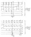
- ECG ECG output
- QRS QRS beats
- STIM stimulating pulses issued by the pacemaker in order to arrest tachycardia
- T D is progressively increased or decreased successively with each subsequent stimulating pulse issued until the tachycardia is arrested.
- Tp is preset to a proportion of the RR interval during tachycardia and will commonly be about one half. Such a circumstance provides the most likely result that To is correct upon the first occurrence of a stimulating pulse, but, if not, it is likely to be close to the window such that normally only one or two further stimulating pulses (at increased or decreased T as the case may be) are issued.
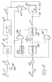
- a sensing electrode 2 supplies an input amplifier 4, the output of which is fed successively to a QRS detector 6, a ramp generator and level detector 8 and an AND gate 10 with one inverted input.
- the QRS detector 6 is typically a frequency selective network centred about the 17 ms half triangle, for example a twin T filter as in known pacemakers.
- the AND gate 10 controls a counter 12 supplying output pulses after a count of 3, these output pulses firing a monostable 14 of adjustable pulse width (see below).
- the monostable 14 controls a further monostable 16 (having an output pulse width of 0.5 ms).
- the output of monostable 16 after amplification by an output amplifier 18, is fed to a pacing electrode 20 whereby to provide a stimulus to the heart.
- the output of monostable 16 is also fed to a further monostable 22 (10 ms pulse width) which in turn controls inputs on AND gates 24 and 26.
- the output from the QRS detector 6 is also supplied to inputs on AND gates 10, 24 and 26 (the latter input being inverted).
- the respective outputs from AND gates 24 and 26 control the pulse width of monostable 14 (see description below in relation to Figure 4).
- the counter 12 is reset by its own output or by the output from the ramp generator and level detector 8.
- the input from sensing electrode 2 is muted during a pacing stimulus to reduce the likelihood of the stimulus causing the input amplifier 4 to block.
- this muting is shown schematically as a switch 28, in practice it would be accomplished electronically, such as in the input amplifier 4 before the first AC coupling.
- waveform B Every output from QRS detector 6 (waveform B) resets the ramp generator 8. If the ramp (waveform C) rises to above a preset level (which is set dependent upon the minimum tachycardia rate at which the pacemaker is to operate) a pulse (waveform D) is generated which finishes slightly after the trailing edge of the QRS pulse.
- the AND gate 10 only provides output pulses when input pulses are received from the QRS detector 6 and when input pulses from the level detector in 8 are absent. This condition arises only when the heart is in a tachycardia situation.
- the adjustable pulse width of monostable 14 (T D ) is employed to ensure that the stimulating pulses are issued within the window necessary to terminate the tachycardia.
- T D is too long.
- the stimulus thus causes a paced beat.
- the coincidence of a paced beat following a stimulating pulse is detected by AND gate 24 which issues a pulse to decrease T of monostable 14 (see below).
- a reversal of the operation described in the preceding paragraph arises: T D will be progressively reduced until the window is reached and the tachycardia is arrested or T D becomes too short and the paced beats cease. This situation is illustrated in Figure 3(iii).
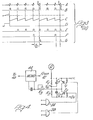
- a typical circuit for controlling T D is illustrated in Figure 4.
- V m is quickly established by C 1 and C 2 ; the ratios R 1 :R 2 and C 1 :C 2 being the same.
- V m may be raised or lowered by switching on T 1 and T 2 for discrete periods and this will shorten or lengthen T D accordingly.
- the resistor R 3 is preset to an average T D for the particular patient under treatment.
- This T D is a specific preset proportion of the RR interval of the patient at any particular time. If it is desired to cause this proportion to vary with a variation in the RR interval, this can be achieved, for example, by coupling the circuit shown in Figure 5, at point Q, to the circuit shown in Figure 4.
- a sample and hold circuit 30 holds the peak value of the ramp voltage generated in 8 and is reset by the output of the level detector in 8.
- the output of circuit 30 is passed through a shaping network 32 and invertor 34 to point Q in Figure 4.
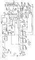
- a pacemaker circuit for accomplishing tachycardia control in this manner is shown in Figure 7, where components common to those in Figure 2 are given identical reference numerals.
- a single sensing/pacing electrode 2/20 with biphasic stimulus pulses is employed.
- a ramp generator 100 is reset by the trailing edge of pulses from the QRS detector 6 and feeds level detectors 102, 104, 106.
- the level at which detector 102 is actuated is controlled by variable resistor 108 which acts to set the minimum tachycardia rate at which the pacemaker is to operate.
- the ramp generator 100 also feeds a sample and hold circuit 110, the output of which is fed to the level setting inputs of detectors 104 and 106 (at a and b respectively).
- the output of level detector 102 is also supplied to gate 116.
- the counter 118 counts up to three and the "1" and “2" outputs are supplied to AND gates 120 and 122 respectively.
- Second inputs to AND gates 120 and 122 are provided from the QRS detector 6.
- the outputs of AND gates 120 and 122 are employed to control the pulse width T of monostable 14 in the manner accomplished by AND gates 24 and 26 in Figures 2 and 4.
- the QRS detector output is also employed to close transmission gate 116 and, after passage through a delay monostable 124, to reset counter 118.
- the counter 12 supplies the sample signal to sample and hold circuit 110.
- the monostable 14 feeds a pair of monostables 126, 128 each of 0.5 ms pulse width. Outputs from both 126, 128 are provided to output amplifier 18 whereas the output of monostable 126 is also employed to reset the ramp generator 100 and open transmission gate 116.
- the detection circuitry does not come into operation until a third tachycardia pulse is observed.
- the sample and hold circuit 110 passes a voltage to level detectors 104 and 106.
- a pulse is produced by monostable 114 as the ramp passes voltage b (waveform J).
- a pulse is produced by monostable 112 as the ramp passes voltage a (waveform I).
- the pulse marked ** in J may or may not be present but it is of no consequence.
- the transmission gate 116 opened by the issuance of the stimulus pulse, passes these two pulses, together with that produced from level detector 102 (waveform D) to counter 118 (waveform L).
- the output of gate 116 is the gated sum of waveforms D, I, and J (in this case 3). Since we have assumed that, in this case, T is correct and the tachycardia has been arrested, the pacemaker takes no further action (until a fresh tachycardia is detected). In such a circumstance no output is supplied to the delay monostable 14 via AND gates 120 and 122 (i.e. To is not adjusted).
- the counter 12 in Figure 7 is shown as being capable of being reset either by level detector 102 or by its own output, it is preferred to employ the latter when attempting to detect tachycardia conditions not far removed from normal cardiac beat conditions (in terms of beat interval). If the level detector 102 is used to reset counter 12 under such conditions, difficulties can arise in the circuit. On the other hand, resetting counter 12 from the level detector 102 rather than from its own output results in a faster response for the pacemaker (this applies also to the Figure 2 embodiment).
Landscapes
- Health & Medical Sciences (AREA)
- Cardiology (AREA)
- Heart & Thoracic Surgery (AREA)
- Engineering & Computer Science (AREA)
- Biomedical Technology (AREA)
- Nuclear Medicine, Radiotherapy & Molecular Imaging (AREA)
- Radiology & Medical Imaging (AREA)
- Life Sciences & Earth Sciences (AREA)
- Animal Behavior & Ethology (AREA)
- General Health & Medical Sciences (AREA)
- Public Health (AREA)
- Veterinary Medicine (AREA)
- Electrotherapy Devices (AREA)
Claims (17)
Priority Applications (1)
| Application Number | Priority Date | Filing Date | Title |
|---|---|---|---|
| AT80300658T ATE2771T1 (de) | 1979-03-07 | 1980-03-05 | Schrittmacher fuer tachykardieueberwachung. |
Applications Claiming Priority (2)
| Application Number | Priority Date | Filing Date | Title |
|---|---|---|---|
| GB7907998 | 1979-03-07 | ||
| GB7907998 | 1979-03-07 |
Publications (2)
| Publication Number | Publication Date |
|---|---|
| EP0016574A1 EP0016574A1 (de) | 1980-10-01 |
| EP0016574B1 true EP0016574B1 (de) | 1983-03-16 |
Family
ID=10503676
Family Applications (1)
| Application Number | Title | Priority Date | Filing Date |
|---|---|---|---|
| EP80300658A Expired EP0016574B1 (de) | 1979-03-07 | 1980-03-05 | Schrittmacher für Tachykardieüberwachung |
Country Status (4)
| Country | Link |
|---|---|
| US (1) | US4312356A (de) |
| EP (1) | EP0016574B1 (de) |
| AT (1) | ATE2771T1 (de) |
| DE (1) | DE3062312D1 (de) |
Families Citing this family (35)
| Publication number | Priority date | Publication date | Assignee | Title |
|---|---|---|---|---|
| DE3110015A1 (de) * | 1980-03-25 | 1982-03-25 | Telectronics Pty. Ltd., Lane Cove, New South Wales | Mit zwei impulsen arbeitender tachykardie-regelschrittmacher |
| DE3110014A1 (de) * | 1980-05-19 | 1982-03-25 | Telectronics Pty. Ltd., Lane Cove, New South Wales | Aeusserlich rueckstellbarer tachykardie-regelschrittmacher |
| DE3110013A1 (de) * | 1981-03-11 | 1982-09-23 | Telectronics Pty. Ltd., Lane Cove, New South Wales | Ratebezogener tachykardie-regelschrittmacher |
| US4407289A (en) * | 1981-03-23 | 1983-10-04 | Telectronics Pty. Ltd. | Externally-reset tachycardia control pacer |
| EP0077807B1 (de) * | 1981-05-04 | 1987-11-19 | BIOTRONIK Mess- und Therapiegeräte GmbH & Co Ingenieurbüro Berlin | Herzschrittmacher |
| US4406287A (en) * | 1981-07-17 | 1983-09-27 | Telectronics Pty. Ltd. | Variable length scanning burst tachycardia control pacer |
| US4398536A (en) * | 1981-07-17 | 1983-08-16 | Telectronics Pty. Ltd. | Scanning burst tachycardia control pacer |
| DE3175940D1 (en) * | 1981-10-26 | 1987-04-09 | Vitafin Nv | Programmable cardiac pacemaker |
| DE3207006A1 (de) * | 1982-02-26 | 1983-09-08 | Siemens AG, 1000 Berlin und 8000 München | Av-sequenzieller herzschrittmacher |
| US4427011A (en) | 1982-03-18 | 1984-01-24 | Telectronics Pty. Ltd. | Tachycardia control pacer with improved detection of tachycardia termination |
| US4614192A (en) * | 1982-04-21 | 1986-09-30 | Mieczyslaw Mirowski | Implantable cardiac defibrillator employing bipolar sensing and telemetry means |
| US4515160A (en) * | 1982-04-23 | 1985-05-07 | Medtronic, Inc. | Cardiac pacemaker synchronized programming |
| US4493325A (en) * | 1982-05-03 | 1985-01-15 | Medtronic, Inc. | Tachyarrhythmia pacer |
| US4559946A (en) * | 1982-06-18 | 1985-12-24 | Mieczyslaw Mirowski | Method and apparatus for correcting abnormal cardiac activity by low energy shocks |
| DE3240430A1 (de) * | 1982-11-02 | 1984-05-03 | Siemens AG, 1000 Berlin und 8000 München | Verfahren und herzschrittmacher zum beenden einer tachykardie |
| US4554920A (en) * | 1982-11-22 | 1985-11-26 | Intermedics, Inc. | Microprocessor controlled cardiac pacemaker and method for avoiding pacer sustained tachycardia |
| US4712556A (en) * | 1982-11-22 | 1987-12-15 | Intermedics, Inc. | Pacemaker and method for ventricular rate limit operation and termination of pacemaker mediated tachycardia |
| EP0110612B1 (de) * | 1982-11-22 | 1988-02-10 | Intermedics, Inc. | Mikroprozessor-gesteuerter Herzschrittmacher mit begrenzter Ventrikel-Schrittfrequenz |
| US4577633A (en) * | 1984-03-28 | 1986-03-25 | Medtronic, Inc. | Rate scanning demand pacemaker and method for treatment of tachycardia |
| US4587970A (en) * | 1985-01-22 | 1986-05-13 | Telectronics N.V. | Tachycardia reversion pacer |
| CA1290813C (en) * | 1985-08-12 | 1991-10-15 | Michael B. Sweeney | Pacemaker for detecting and terminating a tachycardia |
| US4830006B1 (en) * | 1986-06-17 | 1997-10-28 | Intermedics Inc | Implantable cardiac stimulator for detection and treatment of ventricular arrhythmias |
| US5103822A (en) * | 1990-04-03 | 1992-04-14 | Siemens-Pacesetter, Inc. | Pacing system for termination of cardiac arrhythmias utilizing scanning techniques |
| EP0642368B1 (de) * | 1992-04-06 | 1999-01-27 | Angeion Corporation | Gerät zur behandlung von herzkammer-tachykardien mittels reihe von entferntenfeld-impulsen |
| US5718235A (en) * | 1992-10-06 | 1998-02-17 | Gw Scientific, Inc. | Detection of abnormal and induction of normal heart rate variability |
| US5891044A (en) * | 1992-10-06 | 1999-04-06 | Gw Scientific, Inc. | Detection of abnormal and induction of normal heart rate variability |
| WO1995007728A2 (en) * | 1993-09-15 | 1995-03-23 | Pacesetter, Inc. | Synchronized cardioverter shock therapy for preemptive depolarization |
| US5431689A (en) * | 1993-09-23 | 1995-07-11 | Pacesetter, Inc. | Implantable stimulation system and method for terminating cardiac arrhythmias |
| AU3070495A (en) * | 1994-07-13 | 1996-02-16 | Gw Scientific Inc. | Detection of abnormal and induction of normal heart rate variability |
| US5620471A (en) * | 1995-06-16 | 1997-04-15 | Pacesetter, Inc. | System and method for discriminating between atrial and ventricular arrhythmias and for applying cardiac therapy therefor |
| US6487442B1 (en) | 2000-04-28 | 2002-11-26 | Nicholas Wood | Detection of abnormal and induction of normal heat rate variability |
| US7392082B2 (en) * | 2003-09-26 | 2008-06-24 | Medtronic, Inc. | Inter-episode implementation of closed loop ATP |
| US7792578B2 (en) * | 2006-02-15 | 2010-09-07 | Medtronic, Inc. | Method and device for delivering anti-tachycardia pacing therapy |
| US8064999B2 (en) * | 2009-01-30 | 2011-11-22 | Medtronic, Inc. | Distance-based analysis of return cycles for tachycardia discrimination |
| US10905884B2 (en) | 2012-07-20 | 2021-02-02 | Cardialen, Inc. | Multi-stage atrial cardioversion therapy leads |
Family Cites Families (5)
| Publication number | Priority date | Publication date | Assignee | Title |
|---|---|---|---|---|
| FR2120470A6 (de) * | 1970-03-24 | 1972-08-18 | Zacouto Fred | |
| FR2082703A5 (de) * | 1970-03-24 | 1971-12-10 | Zacouto Fred | |
| US3698398A (en) * | 1970-11-06 | 1972-10-17 | American Optical Corp | Rate-scanning pacer for treatment of tachycardia |
| GB1493353A (en) * | 1973-11-21 | 1977-11-30 | Devices Implants Ltd | Device for terminating tachycardia |
| GB1538522A (en) * | 1975-09-30 | 1979-01-17 | Mirowski M | Apparatus for detecting the state of a heart and for cardioverting a malfunctioning heart |
-
1980
- 1980-02-26 US US06/124,667 patent/US4312356A/en not_active Expired - Lifetime
- 1980-03-05 AT AT80300658T patent/ATE2771T1/de not_active IP Right Cessation
- 1980-03-05 DE DE8080300658T patent/DE3062312D1/de not_active Expired
- 1980-03-05 EP EP80300658A patent/EP0016574B1/de not_active Expired
Also Published As
| Publication number | Publication date |
|---|---|
| ATE2771T1 (de) | 1983-04-15 |
| EP0016574A1 (de) | 1980-10-01 |
| DE3062312D1 (en) | 1983-04-21 |
| US4312356A (en) | 1982-01-26 |
Similar Documents
| Publication | Publication Date | Title |
|---|---|---|
| US4312356A (en) | Pacemakers for tachycardia control | |
| US4228803A (en) | Physiologically adaptive cardiac pacemaker | |
| US3942534A (en) | Device for terminating tachycardia | |
| US3920024A (en) | Threshold tracking system and method for stimulating a physiological system | |
| US4569350A (en) | System for detecting pacer mediated tachycardia | |
| US5584867A (en) | Method and apparatus for controlling a double atrial triple chamber cardiac pacemaker having a fallback mode | |
| US4312355A (en) | Heart pacemaker | |
| CA1091302A (en) | Pacer with automatically variable a-v interval | |
| US5129392A (en) | Apparatus for automatically inducing fibrillation | |
| US5188105A (en) | Apparatus and method for treating a tachyarrhythmia | |
| AU616374B2 (en) | Atrial rate based programmable pacemaker with automatic mode switching means | |
| CA1310703C (en) | Method and apparatus for cardioverter/pacer featuring a blanked pacing channel and a rate detect channel with agc | |
| US4587970A (en) | Tachycardia reversion pacer | |
| US4393877A (en) | Heart rate detector | |
| US4781194A (en) | Heart pacemaker | |
| US4378020A (en) | Dual chamber pacer | |
| US4421114A (en) | Tachycardia treatment | |
| US5423868A (en) | Dual chamber pacemaker which detects, confirms and terminates pacemaker mediated tachycardia | |
| EP0007189B1 (de) | An physiologische Zustände anpassungsfähiger Herzschrittmacher | |
| CA1098587A (en) | Atrial-ventricular synchronized pacemaker | |
| US4574437A (en) | Methods and device for terminating tachycardia | |
| US4593695A (en) | Pacemaker with improved tachycardia treatment means and method | |
| US3783878A (en) | Atrial and ventricular pacer having independent rate and av delay controls | |
| EP1206301A1 (de) | Herzschrittmacher | |
| EP0836867A1 (de) | Herzschrittmacher zur Vermeidung von Problemen beim Zusammenfall von Herzkammer-Reizungspulsen und Herzschlag |
Legal Events
| Date | Code | Title | Description |
|---|---|---|---|
| PUAI | Public reference made under article 153(3) epc to a published international application that has entered the european phase |
Free format text: ORIGINAL CODE: 0009012 |
|
| AK | Designated contracting states |
Designated state(s): AT BE CH DE FR GB IT NL SE |
|
| 17P | Request for examination filed |
Effective date: 19810313 |
|
| ITF | It: translation for a ep patent filed | ||
| GRAA | (expected) grant |
Free format text: ORIGINAL CODE: 0009210 |
|
| AK | Designated contracting states |
Designated state(s): AT BE CH DE FR GB IT NL SE |
|
| REF | Corresponds to: |
Ref document number: 2771 Country of ref document: AT Date of ref document: 19830415 Kind code of ref document: T |
|
| REF | Corresponds to: |
Ref document number: 3062312 Country of ref document: DE Date of ref document: 19830421 |
|
| ET | Fr: translation filed | ||
| PLBI | Opposition filed |
Free format text: ORIGINAL CODE: 0009260 |
|
| 26 | Opposition filed |
Opponent name: BIOTRONIK MESS- UND THERAPIEGERAETE GMBH & CO Effective date: 19831216 |
|
| PLAB | Opposition data, opponent's data or that of the opponent's representative modified |
Free format text: ORIGINAL CODE: 0009299OPPO |
|
| R26 | Opposition filed (corrected) |
Opponent name: BIOTRONIK MESS- UND THERAPIEGERAETE GMBH & CO Effective date: 19831221 |
|
| R20 | Corrections of a patent specification |
Effective date: 19871208 |
|
| PLBN | Opposition rejected |
Free format text: ORIGINAL CODE: 0009273 |
|
| STAA | Information on the status of an ep patent application or granted ep patent |
Free format text: STATUS: OPPOSITION REJECTED |
|
| 27O | Opposition rejected |
Effective date: 19880214 |
|
| NLR2 | Nl: decision of opposition | ||
| PGFP | Annual fee paid to national office [announced via postgrant information from national office to epo] |
Ref country code: CH Payment date: 19900622 Year of fee payment: 11 |
|
| PGFP | Annual fee paid to national office [announced via postgrant information from national office to epo] |
Ref country code: GB Payment date: 19910218 Year of fee payment: 12 |
|
| PGFP | Annual fee paid to national office [announced via postgrant information from national office to epo] |
Ref country code: AT Payment date: 19910301 Year of fee payment: 12 |
|
| PGFP | Annual fee paid to national office [announced via postgrant information from national office to epo] |
Ref country code: BE Payment date: 19910320 Year of fee payment: 12 |
|
| PGFP | Annual fee paid to national office [announced via postgrant information from national office to epo] |
Ref country code: SE Payment date: 19910327 Year of fee payment: 12 |
|
| ITTA | It: last paid annual fee | ||
| PG25 | Lapsed in a contracting state [announced via postgrant information from national office to epo] |
Ref country code: CH Effective date: 19910331 |
|
| REG | Reference to a national code |
Ref country code: CH Ref legal event code: PL |
|
| PG25 | Lapsed in a contracting state [announced via postgrant information from national office to epo] |
Ref country code: GB Effective date: 19920305 Ref country code: AT Effective date: 19920305 |
|
| PG25 | Lapsed in a contracting state [announced via postgrant information from national office to epo] |
Ref country code: SE Effective date: 19920306 |
|
| PG25 | Lapsed in a contracting state [announced via postgrant information from national office to epo] |
Ref country code: BE Effective date: 19920331 |
|
| BERE | Be: lapsed |
Owner name: SIEMENS A.G. Effective date: 19920331 |
|
| GBPC | Gb: european patent ceased through non-payment of renewal fee | ||
| EUG | Se: european patent has lapsed |
Ref document number: 80300658.4 Effective date: 19921005 |
|
| ITPR | It: changes in ownership of a european patent |
Owner name: CESSIONE;PACESETTER AB |
|
| REG | Reference to a national code |
Ref country code: FR Ref legal event code: TP |
|
| NLS | Nl: assignments of ep-patents |
Owner name: PACESETTER AB |
|
| PGFP | Annual fee paid to national office [announced via postgrant information from national office to epo] |
Ref country code: NL Payment date: 19980320 Year of fee payment: 19 |
|
| PGFP | Annual fee paid to national office [announced via postgrant information from national office to epo] |
Ref country code: DE Payment date: 19990318 Year of fee payment: 20 |
|
| PGFP | Annual fee paid to national office [announced via postgrant information from national office to epo] |
Ref country code: FR Payment date: 19990319 Year of fee payment: 20 |
|
| PG25 | Lapsed in a contracting state [announced via postgrant information from national office to epo] |
Ref country code: NL Free format text: LAPSE BECAUSE OF NON-PAYMENT OF DUE FEES Effective date: 19991001 |
|
| NLV4 | Nl: lapsed or anulled due to non-payment of the annual fee |
Effective date: 19991001 |
|
| APAH | Appeal reference modified |
Free format text: ORIGINAL CODE: EPIDOSCREFNO |