EP0016739A1 - Verfahren und Vorrichtung zum automatischen Vernähen von Pantyhosen mit Zwickelstück - Google Patents
Verfahren und Vorrichtung zum automatischen Vernähen von Pantyhosen mit Zwickelstück Download PDFInfo
- Publication number
- EP0016739A1 EP0016739A1 EP80850018A EP80850018A EP0016739A1 EP 0016739 A1 EP0016739 A1 EP 0016739A1 EP 80850018 A EP80850018 A EP 80850018A EP 80850018 A EP80850018 A EP 80850018A EP 0016739 A1 EP0016739 A1 EP 0016739A1
- Authority
- EP
- European Patent Office
- Prior art keywords
- suction
- panty
- hose
- station
- assembly
- Prior art date
- Legal status (The legal status is an assumption and is not a legal conclusion. Google has not performed a legal analysis and makes no representation as to the accuracy of the status listed.)
- Withdrawn
Links
- 238000004826 seaming Methods 0.000 title claims abstract description 83
- 238000000034 method Methods 0.000 title claims description 17
- 230000000712 assembly Effects 0.000 claims abstract description 13
- 238000000429 assembly Methods 0.000 claims abstract description 13
- 210000000689 upper leg Anatomy 0.000 claims description 15
- 239000000463 material Substances 0.000 claims description 14
- 210000002414 leg Anatomy 0.000 claims description 6
- 238000010276 construction Methods 0.000 description 9
- 238000004891 communication Methods 0.000 description 5
- 230000006835 compression Effects 0.000 description 4
- 238000007906 compression Methods 0.000 description 4
- 238000009958 sewing Methods 0.000 description 4
- 230000005540 biological transmission Effects 0.000 description 3
- 238000004519 manufacturing process Methods 0.000 description 3
- 238000005192 partition Methods 0.000 description 2
- 230000002093 peripheral effect Effects 0.000 description 2
- 230000001360 synchronised effect Effects 0.000 description 2
- 210000003371 toe Anatomy 0.000 description 2
- 229920000742 Cotton Polymers 0.000 description 1
- 229920001875 Ebonite Polymers 0.000 description 1
- 238000005299 abrasion Methods 0.000 description 1
- 239000002131 composite material Substances 0.000 description 1
- 238000007796 conventional method Methods 0.000 description 1
- 238000005520 cutting process Methods 0.000 description 1
- 230000003247 decreasing effect Effects 0.000 description 1
- 230000001419 dependent effect Effects 0.000 description 1
- 238000001514 detection method Methods 0.000 description 1
- 229910003460 diamond Inorganic materials 0.000 description 1
- 239000010432 diamond Substances 0.000 description 1
- 230000000694 effects Effects 0.000 description 1
- 238000011144 upstream manufacturing Methods 0.000 description 1
Images



Classifications
-
- D—TEXTILES; PAPER
- D05—SEWING; EMBROIDERING; TUFTING
- D05B—SEWING
- D05B23/00—Sewing apparatus or machines not otherwise provided for
- D05B23/007—Sewing units for assembling parts of knitted panties or closing the stocking toe part
- D05B23/008—Line closers, i.e. sewing units for forming the body portion of the panty hose
-
- D—TEXTILES; PAPER
- D05—SEWING; EMBROIDERING; TUFTING
- D05D—INDEXING SCHEME ASSOCIATED WITH SUBCLASSES D05B AND D05C, RELATING TO SEWING, EMBROIDERING AND TUFTING
- D05D2207/00—Use of special elements
- D05D2207/02—Pneumatic or hydraulic devices
- D05D2207/04—Suction or blowing devices
-
- D—TEXTILES; PAPER
- D05—SEWING; EMBROIDERING; TUFTING
- D05D—INDEXING SCHEME ASSOCIATED WITH SUBCLASSES D05B AND D05C, RELATING TO SEWING, EMBROIDERING AND TUFTING
- D05D2303/00—Applied objects or articles
- D05D2303/20—Small textile objects e.g., labels, beltloops
Definitions
- the present invention relates to automatic seaming method and apparatus for gored panty-hoses.
- a gored panty-hose is usually made up of a pair of leg sections closed at their toes, a panty section formed integrally with the leg sections, and a gore piece seamed to the inside thigh portion of the panty-section.
- the conventional method of producing the above-described gored panty-hose includes two-staged seaming operations.
- the first stage seaming operation the two leg sections and the panty section are seamed together while leaving an unseamed opening in the inside thigh portion of the panty section by means of skipped seaming technique.
- a separate gore piece is held in portion in said inside thigh opening and the edge thereof is seamed to the unseamed sliced edge defining the opening in order to form a complete panty-hose.
- four sets of vertically constructed suction assemblies travel with an overhead rotary carrier disc from a first to a fourth station provided on an operation table, in an intermittent fashion, so that each suction assembly is located at any of the four stations during intervals.
- incomplete panty-hose having an inside thigh opening are manually set to a suction assembly located at the station.
- a gore piece of a prescribed pattern is passed to the suction assembly so that the edge thereof is superimposed upon the sliced edge on the incomplete panty-hose.
- the superimposed edges are seamed together in order to form complete gored panty-hose which are thereafter removed from the suction assembly at the fourth- station.
- the operations are all carried out in a fully automatic fashion while skillfully utilizing pneumatic suction and exhaustion.
- the process includes two-staged seaming operations.
- a pair of cylindrical stocking materials 1 and 2 of equal size are superposed at the panty section 6 thereof and slicing is applied towards the inside thigh section'.
- the stocking materials 1 and 2 are subjected to the first seaming operation as shown in FIG. 1, in which the front and rear side sliced edges 3 and 4 are seamed together along seaming lines 3a and 4a while leaving a sliced edge 5 in the inside thigh section unseamed.
- Incomplete panty-hose 7 are formed by this operation, having an unseamed opening 5a in the inside thigh section.
- the second seaming operation is very difficult to carry out smoothly, since the seaming has to be practised along an intricate curved seaming line.
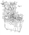
- FIGS. 3 and 4 One embodiment of the seaming apparatus in accordance with the present invention is shown in FIGS. 3 and 4.
- a bottom casing 101 carries atop an operation table 102, and both form a semi-circular section at one end thereof.
- a vertical rotary shaft 103 is arranged at the center of the semi-circular sections, and a carrier disc 104 is fixedly mounted atop the rotary main shaft 103.
- four sets of section tube assemblies 201 are arranged along the periphery of the carrier disc 104 at equal intervals. The number of suction tube assemblies 201 on the carrier disc 104 can be changed freely as required in practice.
- Each suction assembly 201 and the carrier disc 104 rotate about the center of the carrier disc 104 as indicated by an arrow a in the drawing so that each suction assembly 201 can be sequentially located at anyone of four stations I through IV which'are arranged along the periphery of the carrier disc 104 equally spaced.
- the suction assembly 201 holds, by pneumatic suction, the incomplete panty-hose with the opening 5a shown in FIG. 1 at a prescribed position along its outer periphery, the unseamed sliced edge being folded upwards.
- a gore piece transfer assembly 401 transfers the gore piece 10 to proper position in relation to the sliced edge 5 of the incomplete panty-hose held by the suction assembly 201.
- the gore piece 10 sliced in a prescribed shape is fed by a feeding assembly 301.
- the edge of the transferred gore piece 10 is folded upwards so as to be superimposed upon the upwardly folded sliced edge of the incomplete panty-hose.
- the sliced edge of the incomplete panty-hose and the gore piece are clamped together by a clamping assembly 501 and the upwardly folded edges are returned to a horizontal state. Thereupon the clamping assembly 501 starts to rotate so that the sliced edge of the incomplete panty-hose and the edge of the gore piece 10 are seamed together by a sewing assembly 601.
- the carrier disc 104 As mentioned above the carrier disc 104 the construction and operation of which will now be described, is fixedly mounted atop the vertical rotary main shaft 103.
- the main shaft 103 As shown in FIGS. 3 and 5, the main shaft 103 is ro - tatably supported by a cylindrical stand 105 on the operation table 102 by means of a pair of thrust bearings 106 and 107 inserted into the stand 105.
- the main shaft 103 is cylindrical and the lower end thereof is connected to a suction source 108 shown with dot lines in FIG. 3.
- a drive motor 109 with a reduction gear is arranged at a proper position in the bottom casing 101.
- a drive pulley 110a mounted to the output shaft of the motor 109 is coupled over a drive belt 111 to a driven pulley 110b mounted to the lower portion of the main shaft 103.
- the drive motor 109 As the drive motor 109 operates, the main shaft 103 with the carrier disc 104 is driven over the drive belt 111 for rotation in the direction indicated by the arrow a in FIG. 4.
- a proper control device (not shown) is associated with the drive motor 109 so that the rotary shaft is intermittently rotated,each movement thereof covering exactly one-fourth of a revolution.
- a known Geneva drive for a four-station model may be used for this purpose as a substitute for the pulleys 110a, 110b and the belt 111. It is also possible to connect the electric system of the drive motor 109 to a proper timer circuit in order to drive the motor intermittently.
- suction assembly 201 The construction and operation of the suction assembly 201 will be described in more detail with reference to FIGS. 3 and 5.
- each upright outer pipe 203 is fixedly inserted into a corresponding boss 104a on the carrier disc 104 and an inner pipe 204 is placed coaxially within the outer pipe 203.
- the suction assembly 201 is of a composite pipe construction.
- a downwardly flaring flange 205 is rotatably coupled to the lower end of the outer pipe 203 via a thrust bearing 206.
- the flange 205 forms a downwardly flaring wall 205a having a plurality of vertical slots 207.
- the outer wall 205a is coupled to an inner peripheral wall 205c by means of an annular bottom wall 205b, and the inner peripheral wall 205c is coupled at the top end thereof to the lower open end of the inner pipe 204.
- a brim 208 having a plurality of small holes 208a along the periphery thereof is fixedly mounted atop the inner pipe 204. Consequently, the inner pipe 204 is held freely rotatable within the outer pipe 203 over the bottom flange 205 and the top brim 208.
- a horizontal disc 220 is mounted atop the main shaft 103 via a thrust bearing 221 at a position right above the carrier disc 104. As later described in more detail, this horizontal disc 220 is coupled to the removing assembly 701 and, therefore, is held immovable despite rotation of the rotary main shaft 103.
- the top construction of the horizontal disc 220 and its related parts is shown in more detail in FIG. 6.
- An arched groove 222 is formed in the top surface of the horizontal disc, extending from the first station I to the third station III, and a circular hole 223 is also formed in the top surface of the horizontal disc 220 at the fourth station IV.
- the radial positions of the arched groove 222 and the circular hole 223 are selected so that they meet the travelling path of the top openinn of the suction assembly 201 mounted to the carrier disc 104.
- pneumatic communication is established between the suction assembly 201 and the arched groove 222 or the circular hole 223.
- a holding plate 224 for the panty-hose is arranged in the arched groove 222 and is deliniated substantially similar to the arched groove 222.
- a suction duct 225 is also arranged near the arched groove 222.
- the holding plate 224 is located at the same level as the bottom surface of the horizontal disc 220 and is formed with numerous fine suction holes 224a.
- the suction duct 225 is fixed atop the horizontal disc 220, covering the arched groove 222.
- one suction pipe 226 is coupled to the suction duct 225.
- another suction pipe 227 is coupled to the suction duct 225.
- a partition wall 228 is arranged within the suction duct 225 at a position near the third station III (see FIG. 6) in order to separate the interior of the suction duct 225 into two suction chambers 225a and 225b.
- the suction pipe 226 is in communication with the suction chamber 225a whereas the other suction pipe 227 is in communication with the other suction chamber 225b.
- Suction pipe 226 is coupled to a top suction opening 229 of the main shaft 103.
- the other suction pipe 227 has two branches 230 and 231, one branch 230 of which is coupled to the top suction opening 229 of the main shaft 103 via a valve 232, and the other branch 231 of which is coupled to an exhaust post (not shown) of the suction source 108 via a valve 233.
- valve 232 When valve 232 is left open and the other valve 233 is closed, pneumatic suction occurs at the three suction assemblies 201 located at the first, second and third stations I, II and III.
- This pneumatic suction is generated by the suction source 108 and transmitted to the suction chambers 225a and 225b in the suction duct 225 by way of the main shaft 103, the top suction opening 229 and the suction pipes 22'6 and 227. Consequently, the pneumatic suction is further transmitted to the bottom opening of the inner pipe 204 of each suction assembly 201 by way of the suction holes 224a of the holding plate 224. Concurrently with this transmission, pneumatic suction is transmitted to the slots 207 of the bottom flange 205 by way of the small holes 208a of the brim 208 and the cylindrical space between the outer and inner pipes 203 and 204.
- valve 232 When valve 232 is closed, pneumatic suction occurs at each suction assembly 201 as long as the latter travels from the first station I to a position just before the third station III. In other words, pneumatic suction occurs at each suction assembly 201 as long as the latter is in communication with suction chamber 225a in the suction duct 225.
- the suction assembly 201 arrives at the third station III, the suction assembly 201 is brought into communication with the other suction chamber 225b in the suction duct 225, the partition wall 228 in the suction duct 225 prevents transmission of the pneumatic suction to that suction assembly 201.
- the other valve 233 When the other valve 233 is made open in this state, exhaust air from the suction source 108 is led, by way of the branch 231 of the suction pipe 227, to the suction assembly 201 located at the third station III.
- each gore piece 10 is cut into the prescribed pattern by the gore piece feeding assembly 301 at the second station II and held by the transfer assembly 401 via pneumatic suction.
- the gore piece 10 so held by the transfer assembly 401 is then positioned in relation to the sliced edge 5 in the inside thigh section of the incomplete panty-hose held by the suction assembly 201 located at the second station II.
- the edge of the gore piece 10 is held by pneumatic suction of the suction a-ssembly 201 while being superimposed upon the sliced edge of the incomplete panty-hose.
- the gore piece feeding assembly 301 includes a feed reel 303 on which an elongated gore material is rolled.
- the elongated gore material is passed to the gore piece transfer assembly 401 by a pair of feed rollers 306 and 307 after having passed over a guide roller 304 and a dancer roller 305.
- the feed reel 303, the guide roller 304 and the feed rollers 306 and 307 are driven for intermittent one-way rotation.
- the above-described mechanical elements are mounted to a supporting stand 310 fixed on the operation table 102.
- a drive motor 311 is also mounted to the supporting stand 310 and rotates over one complete revolution at every rotation.
- the output shaft of this drive motor 311 is operationally coupled to the feed reel 303 and the rollers 304, 306 and 307 via a suitable transmission mechanism such as a belt drive.
- a pair of triangular cutters 312 and 313 are arranged about midway between the feed rollers 306 and 307 and are movable in the vertical direction.
- An additional cutter 314 is arranged on the downstream side of the feed roller 307.
- the gore material is delivered from the feed reel 303 over a length corresponding to one gore piece 10.
- the drive motor 311 provisionally stops after having rotated over one complete revolution.
- the two cutters 312 and 313 move vertically in order to stamp out the edges of the gore material into triangular shape.
- the downstream cutter 314 moves downwards in order to cut straightly the center line section of the stamped gore material, a gore piece 10 of a substantially diamond pattern thus being prepared.
- the gore piece 10 so pre-pared is placed on the transfer assembly 401.
- the gore material is intermittently delivered from the feed reel 303 and a series of gore pieces 10 of the prescribed pattern are produced sequentially by the stamping and cutting operations.
- a cylindrical bracket 403 is placed at a proper position on the operation table 102, and a carrier mechanism 404 is rotatably coupled to the cylindrical bracket 403.
- the carrier mechanism 404 includes a cylindrical center shaft 405 rotatably inserted into the cylindrical bracket 403, a pair of horizontal support arms 406 extending from the top of the center shaft 405, and cylindrical upright shafts 407 extending upwards one from each of the outer ends of the support arm 406.
- Each upright shaft 407 is provided with slots 407a.
- a circular disc 408 is fixedly mounted horizontally atop each upright shaft 407. The circular disc 408 is provided with numerous fine suction holes 408a.
- a dual-cylindrical drum 410 is disposed to each upright shaft 407 in such an arrangement that the hub 411 thereof is axially slidably passed over the associated upright shaft 407.
- a compression spring 414 is interposed between the top circular disc 408 and the inside bottom of the drum 410, surrounding the hub 411 so that the drum 410 is always resiliently pressed against the associated support arm 406.
- An outer flange 413 is formed at the top edge of the outer wall 412 of the drum 410 in such an arrangement that the top surface of the flange 413 is flush with that of the circular disc 408.
- a compressed air cylinder 415 is vertically fixed to the bottom surface of the operation table 102 at the second station II in such an arrangement that the piston rod 415a thereof projects from the top surface of the operation table 102.
- the top end of the piston rod 415a faces the bottom of the drum 410 spaced therefrom.
- the piston rod 415a moves upwards to thrust the drum 410 upwards while overcoming repulsion of the compression spring 414 placed in the drum 410.
- the relative position of the pair of drums 410 is shown in FIG. 7.
- the right side drum 410 is located close to one end of the gore piece feeding assembly 301 in order to receive a gore piece 10 from the feeding mechanism 301.
- the left side drum 410 is coaxial with a suction assembly 201 located at the second station II. A slight gap is left between the top surface of the drum 410 and the bottom surface of the suction assembly 201 in this state.
- pneumatic suction is generated at the suction assembly 201, the gore piece 10 on the drum 410 is transferred onto the suction assembly 201 by means of that pneumatic suction.
- a pulley 420 is fixedly connected to the bottom end portion of the center shaft 405 of the carrier mechanism 404, and a pulley 421 is fixedly connected to the bottom end portion of the main shaft 103 as shown in FIG. 3.
- the two pulleys 420 and 421 are operationally coupled to each other over a drive belt 422. Consequently, as the center shaft 103 rotates in one direction, the drums 410 rotate about the center axis of the center shaft 405 in the same direction (arrow b in FIG. 4). This rotation of the drums 410 is of course synchronized with that of the main shaft 103.
- the arrangement for the synchronous rotation should be designed so that the diameter ratio of pulleys 420 and 421 is 1:2.
- the carrier mechanism 404 rotates over 180 degrees. Consequently, upon the 180 degrees rotation, the right side drum 410 is brought to the position previously occupied by the left side drum 410 and the left side drum 410 is brought to the position previously occupied by the left side drum 410. Since the main shaft 103 will be stopped after every 90 degrees rotation, the drums 410 will be stopped after every 180 degrees rotation.
- a gore piece 10 is fed from the gore piece feeding assembly 301 to the drum 410 located at the right side position and a gore piece 10 is transferred to a suction assembly 201 from the drum 410 located at the left side position, both positions being in the second station II.
- the bottom end of the center shaft 405 of the carrier mechanism 404 is coupled to one end of a suction conduit 425 for relative rotation but in an air-tight fashion, and the suction conduit 425 is connected to the suction source 108 (see FIG. 3) via a valve 426.
- the valve 426 is normally left closed but rendered open when the carrier mechanism 404 performs the 180 degrees rotation.
- pneumatic suction generated by the suction assembly is transmitted to the interior of each drum 410 by way of the slots 407a of the upright shaft 407 so that the gore piece 10 can be firmly held flat on the circular disc 408 of each drum 410 during the 180 degrees rotation.
- the pneumatic suction is applied to the gore piece 10 by way of the suction holes 408a formed through the circular disc 410. This pneumatic suction is stopped when the drum 410 are involved in the above-described feeding and transfer of the gore piece 10 so that these operations can be performed without any disturbance.
- the clamping assembly 501 is arranged at the third station III in order to clamp from the underside the sliced edge of the incomplete panty-hose and the gore piece in a superimposed state and to turn them for sewing while maintaining the panty-hose and the gore piece in said clamped state.
- the sewing assembly 601 is also arranged at the third station III to sew the clamped edges together dur - ing their turning.
- FIGS. 3 and 8 The construction of these assemblies 501 and 601 is shown in detail in FIGS. 3 and 8.
- a cylindrical bracket 504 is fixed to a proper position on the operation table 102 and holds an upright shaft 503 in an axially slidable and rotatable fashion via bearings 505.
- a clamper head 506 is fixedly inserted over the upright shaft 503.
- the clamper head 506 is arranged below and in axial alignment with a suction assembly 201 located at the third station III.
- the clamper head 506 is provided at the top end with a flat clamper disc 506a made of a highly abrasion-resistant material such as hard rubber.
- the diameter of this clamper disc 506a is substantially equal to that of the flange 205 disposed at the bottom end of the suction assembly 201.
- a thick gear 510 is fixedly inserted over the bottom end portion of the upright shaft 503 at a position below the operation table 102, and a compression spring 511 surrounding the upright shaft 503 is interposed between the bottom surface of the bracket 504 and the top surface of the gear 510 so that the upright shaft 503 is always re- sitiently pressed downwards.
- a channel 512 is fixed to the bottom surface of the operation table 102 and surrounds the bottom end portion of the upright shaft 503 spaced therefrom.
- a pneumatic cylinder 513 and a drive motor 514 are mounted to the channel 512.
- a piston rod 513a of the cylinder 513 is fixedly inserted into the center hole of the gear 510, and a gear 515 fixedly mounted to the output shaft of the drive motor 514 is in meshing engagement with the gear 510 on the upright shaft 503.
- the clamping assembly 501 assumes the position shown in FIG. 8 and the clamper head 506 remains spaced from the bottom flange 205 of the suction assembly 201 as shown with solid lines in the drawing.
- the piston rod 513a pushes the gear 510 with the upright shaft 503 and the clamper head 506 upwards, overcoming the repulsion of the compression spring 511.
- the clamper disc 506a of the clamper head 506 is brought into pressure contact with the annular bottom wall 205b of the bottom flange 205 on the suction assembly 201 as shown with two-dot and dash lines in FIG. 8.
- the drive motor 514 is energized in order to rotate the clamper head 506 with the upright shaft 503 in the counterclockwise direction by means of the gears 510 and 515. Due to the above--described pressure contact, the bottom flange 205 of the suction assembly 201 follows this rotation.
- the sliced edge 5 of the incomplete panty-hose and the gore piece 10 are held together on the suction assembly 201 in the superimposed state as shown with dot lines in the drawing, they are both firmly clamped by the clamper disc 506a on the clamper head 506 and are turned about the center axis of the clamper head 506 while maintaining the clamped superimposed state as the latter is driven for rotation by the drive motor 514.
- the seaming assembly 601 is energized in order to seam the sliced edge 5 of the incomplete panty-hose with the gore piece 10.
- the upwardly folded state of the superimposed edges prevents this seaming operation, that is, the superimposed edges should be rendered to resume the horizontal state before starting the seaming operation in accordance with the present invention in order to carry out a smooth seaming operation.
- the exhaust air from the suction source 108 is supplied to the suction assembly 201 located at the third station III. This is carried out by closing one valve 232 and opening the other valve 233 of the suction system for the suction assemblies 201 (see FIG. 5). In this case, the exhaust air is led to the bottom opening of the suction assembly 201 by means of the top opening thereof and the inner pipe 204.
- a pneumatic ejection nozzle 604 is arranged near the seaming assembly 601 with the opening thereof directed towards the outer surface of the bottom flange 205. In this case, the air ejected from the ejection nozzle 604 forces the folded edges to resume the horizontal state.
- a pneumatic suction nozzle 605 is arranged close to and upstream of a sewing needle 601a of the seaming assembly 601. In this case the suction of the nozzle 605 makes the folded edges resume the horizontal state.
- At least two of the above-described three systems may be employed in combination with each other.
- the complete panty-hose 7 have to be removed from the suction assembly 201 by the removing assembly 701 at the fourth station IV.
- one end of a transfer tube 703 is coupled to the circular hole 223 in the horizontal disc 220 and the other end thereof is coupled to a delivery end 704.
- An upper holder ring 705 is mounted to the horizontal disc 220 and an identical lower holder ring 705 is mounted to the operati-on table 102 in axial alignment with the upper holder ring 705.
- a suction tube 706 is vertically held by the two holder rings 705 independently of the rotation of the main shaft 103.
- One end of the suction tube 706 is coupled to the suction source 108 whereas the other end thereof is coupled to said delivery end 704.
- Pneumatic suction generated by the suction source 108 is transmitted to the interior of the suction assembly 201 located at the fourth station IV by way of the suction tube 706, the delivery end 704, the transfer tube 703 and the circular hole 223 of the horizontal disc 220. Consequently, the complete panty-hose 7 within the inner pipe 204 of the suction assembly 201 are transferred to the delivery end 704 due to the pneumatic suction through the circular hole 223 and the transfer tube 703.
- the suction assembly 201 moves from the first station I to the fourth st.ation IV as the carrier disc 104 rotates over 90 degrees.
- the suction assembly 201 receives a gore piece 10 from the transfer assembly 401 shown in FIG. 7.
- the edge of the gore piece 10 is superimposed upon the sliced edge 5 of the incomplete panty-hose held by the suction assembly 201.
- a gore piece 10 cut into the prescribed pattern is fed onto a drum 410 by the gore piece feeding assembly 301.
- the bottom valve 426 is opened so that the gore piece 10 is sucked to and firmly held on the top circular disc 408 by pneumatic suction acting through the suction holes 408a thereof.
- the drum 410 rotates about the center axis of the center shaft 405 over 180 degrees. This 180 degrees rotation of the drum 410 is carried out concurrently with the movement of the suction assembly 210 from the first station I to the second station II.
- the gore piece 10 on the drum 410 is brought to a position in axial alignment with the overhead suction assembly 201 located at the second station II. Thereafter, the bottom valve 426 is closed in order to relieve the pneumatic suction from the gore piece 10. Simultaneously, the pneumatic cylinder 415 is energized in order to lift the drum 410 to the position shown with dot lines in FIG. 7, the entire edge of the gore piece 410 being folded upwards thereby. Thus, the upwardly folded entire edge of the gore piece 10 is sucked onto and held on the outer surface of the bottom flange 205 in a state superimposed upon the sliced edge 5 of the incomplete panty-hose as shown in FIG. 9C. While this superimposed state of the edges is maintained, the suction assembly 201 moves from the second station II to the third station III.
- the pneumatic cylinder 513 shown in FIG. 8 is energized in order to lift the clamper head 513, and the top clamper disc 506a presses the superimposed edges against the annular bottom wall 205b of the flange 205.
- the top valve 232 in FIG. 5 is closed in order to relieve the pneumatic suction in the interior of the suction assembly 201.
- the other top valve 233 is opened in order to supply the exhaust air from the suction source 108 to the suction assembly 201 so as to force the edges on the flange 205 to resume the horizontal state on the seaming table 603.
- the above-described air ejection nozzle 604 or suction nozzle 605 may be used for the same purpose. In these cases the top valves 232 and 233 are both left closed.
- the drive motor 514 is energized in order to rotate the clamper head 506 about the center axis of the upright shaft 503 so that the superimposed edges are rotated in a similar fashion.
- the seaming assembly 601 starts to seam together the superimposed edges along the seaming line 8 as shown in FIG. 9D.
- superfluous portions are cut off from the sliced edge 5 and the edge of the gore piece 10.
- a gore piece 10 is seamed in position to the inside thigh section of the panty-hose 7 in a substantially circular pattern as shown in FIG. 9E.
- the pneumatic cylinder 513 (see FIG. 8) is de-energized and the clamper head 506 lowers. Then, the suction assembly 201 moves from the third to fourth station IV while holding the complete panty-hose 7 inside. Upon arrival at the fourth station IV, the panty-hose 7 is removed from the suction assembly 201 by the above-described removing as- sembl y 701.
- the transfer assembly 401 may be modified. As hereinbefore described in detail, the transfer assembly 401 transfers each gore piece 10 given by the feeding assembly 301 to a suction assembly 201 located at the second station II to superimpose the edge of the gore piece 10 on the sliced edge 5 of the incomplete panty-hose held on the suction assembly.
- the seaming line on the edge of the gore piece 10 should be exactly in line with that on the sliced edge 5 of the incomplete panty-hose.
- a gore piece 10 made of cotton etc. is well stretchable in the longitudinal direction but less stretchable in the transverse direction. Consequently the stretchable longitudinal direction of the gore piece 10 preferably should be adjusted in line with seaming lines 3a and 4a on either sides of the sliced edge 5 of the incomplete panty-hose before starting the seaming operation.
- FIGS. 10 and 11 The construction shown in FIGS. 10 and 11 is adapted for this sort of adjustment.
- a compact-type motor 802 is'supported by a bracket 801 mounted to the top edge of the cylindrical stand 105. This motor 802 is driven for rotation by means of electric signals generated by a later described photo--electric sensor 804.
- a roller 803 is fixed to the output shaft of the motor 802 and is placed in pressure contact with the outer wall 205a of the bottom flange 205 on the suction assembly 201 located at the second station II. When the roller 803 rotates in a direction c in FIG. 10, the flange 205 is rotated in the opposite direction d due to the above-described pressure contact.
- the photo-electric sensor 804 is located at a proper position on a straight line X passing through the center axis of the drum 410 and the suction assembly 201 located at the second station II. This photo-electric sensor 804 detects presence of the sliced edge 5 and the seaming line 3a or 4a of the incomplete panty-hose held on the bottom flange 205 of the suction assembly 201 located at the second station II. When the photo-electric sensor 804 detects the presence of the sliced edge 5, the motor 802 is driven for rotation by a detection signal from the sensor 804. When the sensor 804 detects presence of the seaming line 3a or 4a, rotation of the motor 802 is stopped.
- the photo-electric sensor 804 detects presence of the sliced edge 5 when the seaming lines 3a and 4a are off the above-described straight line X, and the motor 802 is driven for rotation.
- the roller 803 on the output shaft of the motor 802 rotates in the direction c and the flange 205 is rotated in the opposite direction d.
- the photo-electric sensor 804 detects presence of the seaming lines 3a and 4a on the straight line X in order to stop rotation of-the motor 802.
- no rotation of the motor 802 is caused.
- the edge of the gore piece is superimposed upon the sliced edge 5 of the incomplete panty-hose by the transfer assembly after exact registration of the seaming lines 3a and 4a at the straight line X having been confirmed by the photo-electric sensor 804.
- seaming of a gore piece to the thigh section of an incomplete panty-hose is carried out in almost fully automatic fashion without requiring any highly skilled manual technique.
- the only manual operation required is to set the incomplete panty-hose to each suction assembly at the first station I.
- four types of operations i.e. setting incomplete panty-hose to each suction assembly, superimposing a gore piece edge upon the incomplete panty-hose sliced edge, seaming the superimposed edges and removing the complete panty-hose from the suction assembly, are carried out quite concurrently with each other at four different stations, the total operation time necessary for producing set of gored panty-hose being greatly cut down thereby.
Landscapes
- Engineering & Computer Science (AREA)
- Textile Engineering (AREA)
- Sewing Machines And Sewing (AREA)
- Treatment Of Fiber Materials (AREA)
- Socks And Pantyhose (AREA)
Applications Claiming Priority (2)
| Application Number | Priority Date | Filing Date | Title |
|---|---|---|---|
| JP3157079A JPS55128001A (en) | 1979-03-16 | 1979-03-16 | Method and apparatus for sewing gore cloth to inside of thigh of panty stocking |
| JP31570/79 | 1979-03-16 |
Publications (1)
| Publication Number | Publication Date |
|---|---|
| EP0016739A1 true EP0016739A1 (de) | 1980-10-01 |
Family
ID=12334829
Family Applications (1)
| Application Number | Title | Priority Date | Filing Date |
|---|---|---|---|
| EP80850018A Withdrawn EP0016739A1 (de) | 1979-03-16 | 1980-02-18 | Verfahren und Vorrichtung zum automatischen Vernähen von Pantyhosen mit Zwickelstück |
Country Status (4)
| Country | Link |
|---|---|
| US (1) | US4570556A (de) |
| EP (1) | EP0016739A1 (de) |
| JP (1) | JPS55128001A (de) |
| IT (1) | IT1124164B (de) |
Cited By (2)
| Publication number | Priority date | Publication date | Assignee | Title |
|---|---|---|---|---|
| EP0069080A1 (de) * | 1981-06-30 | 1983-01-05 | SOLIS S.r.l. | Kontrollvorrichtung für Nähmaschinen zum Einnähen eines Zwickels in ein Kleidungstück |
| WO1993000467A1 (en) * | 1991-06-20 | 1993-01-07 | H. Flude & Co. (Hinckley) Ltd. | Automatic spade gusset seaming apparatus |
Families Citing this family (3)
| Publication number | Priority date | Publication date | Assignee | Title |
|---|---|---|---|---|
| DE3709210A1 (de) * | 1987-03-20 | 1988-09-29 | Kochs Adler Ag | Falteinrichtung fuer einen naehautomaten |
| GB8807547D0 (en) * | 1988-03-30 | 1988-05-05 | Flude & Hinckley | Automatic flat seaming apparatus |
| ITMI20042084A1 (it) * | 2004-11-02 | 2005-02-02 | Cesare Colosio S P A | Dispositivo di cucitura automatica particolarmente per macchine per calze |
Citations (4)
| Publication number | Priority date | Publication date | Assignee | Title |
|---|---|---|---|---|
| US2982238A (en) * | 1958-08-28 | 1961-05-02 | Jr Frank H Fromm | Sewing apparatus |
| GB2001238A (en) * | 1977-04-04 | 1979-01-31 | Flude & Co Ltd H | Hosiery |
| LU81445A1 (fr) * | 1978-12-06 | 1979-09-12 | Aznar Sa | Procede et machine pour la couture automatique de renforts sur vetements |
| DE2924454A1 (de) * | 1978-07-07 | 1980-01-17 | Solis Sarl | Verfahren und vorrichtung zum anbringen eines zwickels an gegenstaenden, wie strumpfhosen u.a. aehnlichen erzeugnissen |
Family Cites Families (2)
| Publication number | Priority date | Publication date | Assignee | Title |
|---|---|---|---|---|
| US4220104A (en) * | 1977-04-04 | 1980-09-02 | Paramount Textile Machinery Co. | Hosiery |
| JPS5576197A (en) * | 1978-12-01 | 1980-06-09 | Scapa Canada | Handling method and apparatus of roll for paper making endless belt |
-
1979
- 1979-03-16 JP JP3157079A patent/JPS55128001A/ja active Pending
- 1979-08-28 IT IT12718/79A patent/IT1124164B/it active
-
1980
- 1980-02-18 EP EP80850018A patent/EP0016739A1/de not_active Withdrawn
- 1980-03-17 US US06/130,850 patent/US4570556A/en not_active Expired - Lifetime
Patent Citations (4)
| Publication number | Priority date | Publication date | Assignee | Title |
|---|---|---|---|---|
| US2982238A (en) * | 1958-08-28 | 1961-05-02 | Jr Frank H Fromm | Sewing apparatus |
| GB2001238A (en) * | 1977-04-04 | 1979-01-31 | Flude & Co Ltd H | Hosiery |
| DE2924454A1 (de) * | 1978-07-07 | 1980-01-17 | Solis Sarl | Verfahren und vorrichtung zum anbringen eines zwickels an gegenstaenden, wie strumpfhosen u.a. aehnlichen erzeugnissen |
| LU81445A1 (fr) * | 1978-12-06 | 1979-09-12 | Aznar Sa | Procede et machine pour la couture automatique de renforts sur vetements |
Cited By (2)
| Publication number | Priority date | Publication date | Assignee | Title |
|---|---|---|---|---|
| EP0069080A1 (de) * | 1981-06-30 | 1983-01-05 | SOLIS S.r.l. | Kontrollvorrichtung für Nähmaschinen zum Einnähen eines Zwickels in ein Kleidungstück |
| WO1993000467A1 (en) * | 1991-06-20 | 1993-01-07 | H. Flude & Co. (Hinckley) Ltd. | Automatic spade gusset seaming apparatus |
Also Published As
| Publication number | Publication date |
|---|---|
| IT7912718A0 (it) | 1979-08-28 |
| IT1124164B (it) | 1986-05-07 |
| JPS55128001A (en) | 1980-10-03 |
| US4570556A (en) | 1986-02-18 |
Similar Documents
| Publication | Publication Date | Title |
|---|---|---|
| US4962897A (en) | Web winding machine and method | |
| US4856725A (en) | Web winding machine and method | |
| US4723724A (en) | Web winding machine and method | |
| EP1726278B1 (de) | Verfahren und Maschine zum Querfalten und zur Ausrüstung von Erziehungshöschen | |
| US4044659A (en) | Apparatus for making composite filter plugs | |
| US4444140A (en) | Method of making panty hose and apparatus to make same | |
| EP0016739A1 (de) | Verfahren und Vorrichtung zum automatischen Vernähen von Pantyhosen mit Zwickelstück | |
| KR101489393B1 (ko) | 곡선형 포장 상자를 제작하기 위한 기계 및 방법 | |
| EP0155976B1 (de) | Vorrichtung zum Formen von Kunststoffbelägen in Verschlusskapseln, wie Schraubdeckel und Kronkorken | |
| US4480772A (en) | Sleeve making method and apparatus | |
| EP0016437A1 (de) | Verfahren und Vorrichtung zum automatischen Vernähen von Pantyhosen mit Zwickelstück | |
| US5626706A (en) | Method and apparatus for preparing strip material | |
| US3591044A (en) | Patch-feeding device for cigar-making machine | |
| US3512436A (en) | Apparatus for cutting out wrappers or binders each composed of at least two leaf portions | |
| CS217966B2 (en) | Perforating device for perforating the circumference walls of the filter | |
| GB2074203A (en) | Hosiery toe closing machine | |
| US4267785A (en) | Automatic apparatus for feeding and fitting a gore piece to the inside thigh opening of a stocking material | |
| US2699274A (en) | Paper cap-forming apparatus | |
| US5775062A (en) | Method of continuously feeding wrapping elements in sheet form to a user machine | |
| US4481064A (en) | Dual rotary head banding machine | |
| US5596939A (en) | Apparatus for forming tubular collars | |
| US3607581A (en) | Spin-welding holder and loading apparatus | |
| US1956982A (en) | Method of forming bead flippers | |
| GB2262428A (en) | Device for forming double filter-tipped cigarettes on a filter assembly machine | |
| US4208955A (en) | Container manufacturing apparatus and method |
Legal Events
| Date | Code | Title | Description |
|---|---|---|---|
| PUAI | Public reference made under article 153(3) epc to a published international application that has entered the european phase |
Free format text: ORIGINAL CODE: 0009012 |
|
| AK | Designated contracting states |
Designated state(s): CH DE FR GB NL |
|
| STAA | Information on the status of an ep patent application or granted ep patent |
Free format text: STATUS: THE APPLICATION IS DEEMED TO BE WITHDRAWN |
|
| 18D | Application deemed to be withdrawn |
Effective date: 19811117 |
|
| RIN1 | Information on inventor provided before grant (corrected) |
Inventor name: SENBA, RIKICHI |