EP0016957A1 - Seuil avec un rail de roulement - Google Patents
Seuil avec un rail de roulement Download PDFInfo
- Publication number
- EP0016957A1 EP0016957A1 EP80100912A EP80100912A EP0016957A1 EP 0016957 A1 EP0016957 A1 EP 0016957A1 EP 80100912 A EP80100912 A EP 80100912A EP 80100912 A EP80100912 A EP 80100912A EP 0016957 A1 EP0016957 A1 EP 0016957A1
- Authority
- EP
- European Patent Office
- Prior art keywords
- threshold
- profile
- connecting element
- shaped
- running rail
- Prior art date
- Legal status (The legal status is an assumption and is not a legal conclusion. Google has not performed a legal analysis and makes no representation as to the accuracy of the status listed.)
- Withdrawn
Links
- XAGFODPZIPBFFR-UHFFFAOYSA-N aluminium Chemical compound [Al] XAGFODPZIPBFFR-UHFFFAOYSA-N 0.000 claims description 5
- 229910052782 aluminium Inorganic materials 0.000 claims description 5
- 239000000463 material Substances 0.000 claims description 5
- 241000037488 Coccoloba pubescens Species 0.000 abstract 1
- 238000004519 manufacturing process Methods 0.000 description 4
- 238000010276 construction Methods 0.000 description 3
- 239000011324 bead Substances 0.000 description 2
- 230000015572 biosynthetic process Effects 0.000 description 2
- 230000005494 condensation Effects 0.000 description 2
- 238000009833 condensation Methods 0.000 description 2
- XLYOFNOQVPJJNP-UHFFFAOYSA-N water Substances O XLYOFNOQVPJJNP-UHFFFAOYSA-N 0.000 description 2
- 238000000034 method Methods 0.000 description 1
- 238000003825 pressing Methods 0.000 description 1
- 238000003892 spreading Methods 0.000 description 1
Images
Classifications
-
- E—FIXED CONSTRUCTIONS
- E06—DOORS, WINDOWS, SHUTTERS, OR ROLLER BLINDS IN GENERAL; LADDERS
- E06B—FIXED OR MOVABLE CLOSURES FOR OPENINGS IN BUILDINGS, VEHICLES, FENCES OR LIKE ENCLOSURES IN GENERAL, e.g. DOORS, WINDOWS, BLINDS, GATES
- E06B1/00—Border constructions of openings in walls, floors, or ceilings; Frames to be rigidly mounted in such openings
- E06B1/70—Sills; Thresholds
-
- E—FIXED CONSTRUCTIONS
- E06—DOORS, WINDOWS, SHUTTERS, OR ROLLER BLINDS IN GENERAL; LADDERS
- E06B—FIXED OR MOVABLE CLOSURES FOR OPENINGS IN BUILDINGS, VEHICLES, FENCES OR LIKE ENCLOSURES IN GENERAL, e.g. DOORS, WINDOWS, BLINDS, GATES
- E06B3/00—Window sashes, door leaves, or like elements for closing wall or like openings; Layout of fixed or moving closures, e.g. windows in wall or like openings; Features of rigidly-mounted outer frames relating to the mounting of wing frames
- E06B3/32—Arrangements of wings characterised by the manner of movement; Arrangements of movable wings in openings; Features of wings or frames relating solely to the manner of movement of the wing
- E06B3/34—Arrangements of wings characterised by the manner of movement; Arrangements of movable wings in openings; Features of wings or frames relating solely to the manner of movement of the wing with only one kind of movement
- E06B3/42—Sliding wings; Details of frames with respect to guiding
- E06B3/46—Horizontally-sliding wings
- E06B3/4609—Horizontally-sliding wings for windows
-
- E—FIXED CONSTRUCTIONS
- E06—DOORS, WINDOWS, SHUTTERS, OR ROLLER BLINDS IN GENERAL; LADDERS
- E06B—FIXED OR MOVABLE CLOSURES FOR OPENINGS IN BUILDINGS, VEHICLES, FENCES OR LIKE ENCLOSURES IN GENERAL, e.g. DOORS, WINDOWS, BLINDS, GATES
- E06B3/00—Window sashes, door leaves, or like elements for closing wall or like openings; Layout of fixed or moving closures, e.g. windows in wall or like openings; Features of rigidly-mounted outer frames relating to the mounting of wing frames
- E06B3/04—Wing frames not characterised by the manner of movement
- E06B3/263—Frames with special provision for insulation
- E06B3/26347—Frames with special provision for insulation specially adapted for sliding doors or windows
Definitions
- the invention relates to a threshold with a running rail for a door, a window or the like.
- heavily loaded thresholds for example for lift and slide doors, preferably consist of a tubular profile.
- the production of such tube profiles is quite expensive.
- the object of the invention is to provide a threshold for a door, a window or the like. to create, which is cheaper to manufacture, but can withstand the loads.
- a threshold for a door, a window or the like is formed in accordance with the characterizing part of the first claim. Due to the essentially U-shaped cross-section of the threshold profile, high rigidity and good resilience are already achieved. In the case of heavy weight loads and also rough operation on the construction site, however, it is advantageous if the profile is stiffened at least in a partial area, but possibly also over its entire length, by means of at least one or by means of a continuous connecting link. This at least largely prevents the U-legs from spreading or any other undesirable or harmful deformation of the threshold profile. As stated, the stiffening can extend over the entire length, or it can include only one or more sections spaced apart from one another. In the latter case, particular attention is given to those places that are heavily used or are used in a special way for fastening this threshold.
- a preferred embodiment of the invention provides that the connecting link or links are held in a snap or latching manner on the profile of the threshold. This saves mounting holes and allows simple, quick and safe connection directly at the construction site.
- a further development of the invention provides that in particular at the free ends of the U-legs of the profile a downwardly open latching receptacle is arranged, in particular is formed, and that the or each connecting member has two upwardly directed, strip-shaped latching elements.
- the latching receptacles are expediently fitted in such a way that not only the one or more connecting members are supported on the floor, but also the two leg ends of the threshold. As a result, the connection points are less stressed.
- a further embodiment of the invention provides that the or each connecting link has a receptacle which is open at the bottom for a holding element, in particular for a wall anchor or the like.
- the receptacle has an approximately C-shaped cross section, which is suitable for receiving a T-shaped fastening end of the holding element or wall anchor, for example.
- the threshold be made of extruded aluminum profile, on the side end of which is assignable to the interior of the room, a threshold attachment made of a material of lower thermal conductivity is attached, in particular is latched or snap-fastened.
- the threshold approach is shaped and dimensioned so that only its surface is assigned to the warmer interior. In this respect, despite the use of aluminum for the load-bearing part of the threshold, condensation water is avoided inside the room. In addition, this construction prevents the formation of a cold bridge with the undesirable heat flow.
- the running rail is made in one piece with the profile of the threshold and thus needs it not to be attached separately. This also saves on fasteners, for example fastening screws, and also the process of fastening. Finally, it also saves material.
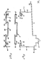
- the threshold consists of a downwardly open, substantially approximately U-shaped profile 1, one or more connecting elements 2 spaced apart and in extension from one another and a running rail 3.
- the latter is made in one piece with the profile 1, whereby it overall is an extruded aluminum profile of the visible in Fig. 1 Cross-section.
- the profile 1 and the connecting member 2 can be snapped together or snapped together.
- this embodiment has the advantage that one attaches short connecting links only at individual points of the profile, thus saving material overall. A continuous connecting link is recommended for the highest loads and loads and also if particularly rough operation is to be expected on site.
- the profile 1 consists of an upper, slightly inclined web 4, on which the profile of the running rail 3 is formed, and two side webs 5 and 6, which start in the region of the longitudinal ends of the upper web 4 and extend approximately perpendicularly thereto.
- the left longitudinal edge of the upper web 4 in FIG. 1 is angled twice in the same sense to form a cross-sectionally C-shaped edge 7.
- the right longitudinal edge 8 is of an angular cross section, which can be seen by angling the upper Bridge 4 reached upwards.
- the profile of the running rail 3 is designed in a known manner and results from the drawing.
- the free ends of the side webs 5 and 6 are angled inward twice at right angles in the same sense. This results in support elements 9 and 10.
- the upward-facing strips 11 and 12 are angled twice again, but in the opposite direction, so that downwardly open catch receptacles 13 and 14 are formed.
- a locking bead 17 or 18 pointing into the interior of the locking receptacle is formed on the end strips 15 or 16. It cooperates with a counterbead 19 or 20 of the or each connecting member 2 in the manner shown in FIG. 2.
- the counter bead is attached to a molded, upright bar 21 or 22 of the connecting member 2.
- the connecting member 2 consists of two base webs 23 and 24, which carry the mentioned strip 21 and 22 on their respective outer longitudinal edge.
- a connecting rail 27 of U-shaped cross section with downward directed U-legs 28 and 29.
- the connecting rail 27 and the two inner longitudinal edges 25 and 26 together form a cross-sectionally C-shaped receptacle 30.
- the downward-facing surfaces 31 and 32 of the base webs 23 and 24 preferably extend in the extension of the downward-facing surfaces 33 and 34 of the base webs 35 and 36 of the profile 1. At the end of the profile pointing to the right in FIG.
- a threshold attachment can be fastened, for example blown open, in a manner not shown, which of course requires corresponding latching receptacles.
- the threshold approach can be made of plastic, for example. The threshold is then installed in such a way that only the threshold extension is located inside the room, and because it consists of a material with a lower thermal conductivity than profile 1, condensation water is avoided inside the room. The formation of a thermal bridge to the outside is also prevented, despite the use of aluminum for the profile 1.
Landscapes
- Engineering & Computer Science (AREA)
- Civil Engineering (AREA)
- Structural Engineering (AREA)
- Wing Frames And Configurations (AREA)
Applications Claiming Priority (2)
| Application Number | Priority Date | Filing Date | Title |
|---|---|---|---|
| DE19797908718 DE7908718U1 (de) | 1979-03-28 | 1979-03-28 | Bodenschwelle mit laufschiene |
| DE7908718U | 1979-03-28 |
Publications (1)
| Publication Number | Publication Date |
|---|---|
| EP0016957A1 true EP0016957A1 (fr) | 1980-10-15 |
Family
ID=6702473
Family Applications (1)
| Application Number | Title | Priority Date | Filing Date |
|---|---|---|---|
| EP80100912A Withdrawn EP0016957A1 (fr) | 1979-03-28 | 1980-02-25 | Seuil avec un rail de roulement |
Country Status (2)
| Country | Link |
|---|---|
| EP (1) | EP0016957A1 (fr) |
| DE (1) | DE7908718U1 (fr) |
Cited By (5)
| Publication number | Priority date | Publication date | Assignee | Title |
|---|---|---|---|---|
| DE19600131A1 (de) * | 1996-01-04 | 1997-07-10 | Neher Systeme Gmbh & Co Kg | Montageanordnung für Schiebeverglasungen |
| EP1057961A3 (fr) * | 1999-05-31 | 2001-12-19 | Gretsch Unitas GmbH Baubeschläge | Seuil pour porte de maison ainsi que porte de maison |
| GB2365052A (en) * | 2000-05-26 | 2002-02-13 | Burnden Group Plc The | Connector, e.g. for window sills |
| EP1359280A3 (fr) * | 2002-04-16 | 2005-06-01 | DORMA GmbH + Co. KG | Ensemble de porte coulissante |
| EP3467246A1 (fr) * | 2017-10-05 | 2019-04-10 | Deceuninck NV | Ensemble de montage pour le montage de portes coulissantes sur un substrat |
Families Citing this family (3)
| Publication number | Priority date | Publication date | Assignee | Title |
|---|---|---|---|---|
| DE7908718U1 (de) * | 1979-03-28 | 1979-06-28 | Gretsch-Unitas Gmbh Baubeschlagfabrik, 7257 Ditzingen | Bodenschwelle mit laufschiene |
| DE19654992C2 (de) * | 1996-01-31 | 1999-02-04 | Peter Willrich | Unterer Abschluß von Türen oder Fenstern |
| DE29721592U1 (de) * | 1997-10-20 | 1999-02-18 | Niemann, Hans Dieter, 50169 Kerpen | Bodenschwelle mit einem Abdichtungsstreifen |
Citations (6)
| Publication number | Priority date | Publication date | Assignee | Title |
|---|---|---|---|---|
| DE1878147U (de) * | 1963-05-21 | 1963-08-22 | Erbsloeh Julius & August | Bauelementensatz fuer eine rahmenkonstruktion. |
| FR1386200A (fr) * | 1964-03-31 | 1965-01-15 | Alumin Building Components Ltd | Perfectionnements aux fenêtres coulissantes |
| US3402512A (en) * | 1966-05-31 | 1968-09-24 | Francis C. Peterson | Adjustable threshold |
| DE6920670U (de) * | 1969-05-21 | 1969-11-27 | Wolfram O Schrom | Horizontalschiebefenster |
| DE7018201U (de) * | 1970-05-15 | 1971-06-03 | Hueck Fa E | Schiebefenster. |
| DE7908718U1 (de) * | 1979-03-28 | 1979-06-28 | Gretsch-Unitas Gmbh Baubeschlagfabrik, 7257 Ditzingen | Bodenschwelle mit laufschiene |
-
1979
- 1979-03-28 DE DE19797908718 patent/DE7908718U1/de not_active Expired
-
1980
- 1980-02-25 EP EP80100912A patent/EP0016957A1/fr not_active Withdrawn
Patent Citations (6)
| Publication number | Priority date | Publication date | Assignee | Title |
|---|---|---|---|---|
| DE1878147U (de) * | 1963-05-21 | 1963-08-22 | Erbsloeh Julius & August | Bauelementensatz fuer eine rahmenkonstruktion. |
| FR1386200A (fr) * | 1964-03-31 | 1965-01-15 | Alumin Building Components Ltd | Perfectionnements aux fenêtres coulissantes |
| US3402512A (en) * | 1966-05-31 | 1968-09-24 | Francis C. Peterson | Adjustable threshold |
| DE6920670U (de) * | 1969-05-21 | 1969-11-27 | Wolfram O Schrom | Horizontalschiebefenster |
| DE7018201U (de) * | 1970-05-15 | 1971-06-03 | Hueck Fa E | Schiebefenster. |
| DE7908718U1 (de) * | 1979-03-28 | 1979-06-28 | Gretsch-Unitas Gmbh Baubeschlagfabrik, 7257 Ditzingen | Bodenschwelle mit laufschiene |
Cited By (8)
| Publication number | Priority date | Publication date | Assignee | Title |
|---|---|---|---|---|
| DE19600131A1 (de) * | 1996-01-04 | 1997-07-10 | Neher Systeme Gmbh & Co Kg | Montageanordnung für Schiebeverglasungen |
| EP1057961A3 (fr) * | 1999-05-31 | 2001-12-19 | Gretsch Unitas GmbH Baubeschläge | Seuil pour porte de maison ainsi que porte de maison |
| GB2365052A (en) * | 2000-05-26 | 2002-02-13 | Burnden Group Plc The | Connector, e.g. for window sills |
| GB2365052B (en) * | 2000-05-26 | 2004-03-03 | Burnden Group Plc The | A connector |
| EP1359280A3 (fr) * | 2002-04-16 | 2005-06-01 | DORMA GmbH + Co. KG | Ensemble de porte coulissante |
| US6973753B2 (en) | 2002-04-16 | 2005-12-13 | Dorma Gmbh + Co. Kg | Sliding door system |
| EP3467246A1 (fr) * | 2017-10-05 | 2019-04-10 | Deceuninck NV | Ensemble de montage pour le montage de portes coulissantes sur un substrat |
| WO2019068899A1 (fr) * | 2017-10-05 | 2019-04-11 | Deceuninck Nv | Montage de base de portes coulissantes sur un substrat |
Also Published As
| Publication number | Publication date |
|---|---|
| DE7908718U1 (de) | 1979-06-28 |
Similar Documents
| Publication | Publication Date | Title |
|---|---|---|
| EP1353034B1 (fr) | Construction de cadre pour porte coulissante | |
| DE2920445A1 (de) | Verschlussanordnung mit verglasung | |
| EP0003042B1 (fr) | Profil d'un châssis pour battant coulissant | |
| EP0016957A1 (fr) | Seuil avec un rail de roulement | |
| EP1057961B1 (fr) | Seuil pour porte de maison ainsi que porte de maison | |
| EP1243738A2 (fr) | Fenêtre mixte bois-aluminium | |
| EP0016958B1 (fr) | Profilé de cadre pour fenêtre, porte ou analogue | |
| DE3107234A1 (de) | "fenster oder tuer mit einer eingebauten schieberlueftung" | |
| DE2443098A1 (de) | Anordnung zur befestigung eines verkleidungsprofiles | |
| AT395133B (de) | Tragleiste fuer einen fahrzeug-gepaeckstraeger | |
| EP0555214A1 (fr) | Toit ou fa ade de serre en particulier | |
| DE29820383U1 (de) | Türschwelle | |
| DE2839740C2 (de) | Schiebe-, Hebeschiebefenster oder -tür | |
| EP0017732B1 (fr) | Seuil, en particulier pour une fenêtre ou une porte | |
| DE2164521A1 (de) | Fertigbauteil fuer fenster- bzw. tueroeffnungen | |
| DE8514453U1 (de) | Lüftungselement | |
| DE19832379A1 (de) | Schiebedach für ein Kraftfahrzeug | |
| DE2338199C2 (de) | Fensterrahmen eines Modernisierungsfensters mit Befestigungseinrichtung für den in der Wand verbleibenden Stockrahmen des alten Fensters | |
| DE2243021C3 (de) | Befestigung einer feststehenden Zarge für Türen oder Fenster an Tragschienen | |
| DE20204563U1 (de) | Thermisch isolierte Türschwelle | |
| DE29912300U1 (de) | Befestigungsvorrichtung | |
| AT282158B (de) | Schiebefenster | |
| DE29718716U1 (de) | Bauteilesatz für eine zweischalige Verkleidung von Holzfenstern | |
| DE19504924A1 (de) | Gebäudefenster oder Gebäudetür, insbesondere auch Gebäudeaußentür, Gebäudefenstertür sowie Schwellenprofil für ein solches Gebäudefenster oder eine solche Gebäudetür | |
| DE2640555B2 (de) | Hängedecke |
Legal Events
| Date | Code | Title | Description |
|---|---|---|---|
| PUAI | Public reference made under article 153(3) epc to a published international application that has entered the european phase |
Free format text: ORIGINAL CODE: 0009012 |
|
| AK | Designated contracting states |
Designated state(s): BE CH FR |
|
| STAA | Information on the status of an ep patent application or granted ep patent |
Free format text: STATUS: THE APPLICATION IS DEEMED TO BE WITHDRAWN |
|
| 18D | Application deemed to be withdrawn |
Effective date: 19811118 |
|
| RIN1 | Information on inventor provided before grant (corrected) |
Inventor name: MAUS, JULIUS |