EP0017194A1 - Installation pour régler automatiquement le jeu d'un dispositif hydraulique - Google Patents
Installation pour régler automatiquement le jeu d'un dispositif hydraulique Download PDFInfo
- Publication number
- EP0017194A1 EP0017194A1 EP80101684A EP80101684A EP0017194A1 EP 0017194 A1 EP0017194 A1 EP 0017194A1 EP 80101684 A EP80101684 A EP 80101684A EP 80101684 A EP80101684 A EP 80101684A EP 0017194 A1 EP0017194 A1 EP 0017194A1
- Authority
- EP
- European Patent Office
- Prior art keywords
- channel
- spring
- cylinder
- piston
- pressure
- Prior art date
- Legal status (The legal status is an assumption and is not a legal conclusion. Google has not performed a legal analysis and makes no representation as to the accuracy of the status listed.)
- Granted
Links
- 239000007788 liquid Substances 0.000 claims description 8
- 238000006073 displacement reaction Methods 0.000 abstract description 4
- 238000010276 construction Methods 0.000 description 10
- 238000004519 manufacturing process Methods 0.000 description 2
- 230000008878 coupling Effects 0.000 description 1
- 238000010168 coupling process Methods 0.000 description 1
- 238000005859 coupling reaction Methods 0.000 description 1
- 230000007423 decrease Effects 0.000 description 1
- 239000012530 fluid Substances 0.000 description 1
- 230000000284 resting effect Effects 0.000 description 1
- 238000007789 sealing Methods 0.000 description 1
- 238000013519 translation Methods 0.000 description 1
- 230000014616 translation Effects 0.000 description 1
Images
Classifications
-
- F—MECHANICAL ENGINEERING; LIGHTING; HEATING; WEAPONS; BLASTING
- F16—ENGINEERING ELEMENTS AND UNITS; GENERAL MEASURES FOR PRODUCING AND MAINTAINING EFFECTIVE FUNCTIONING OF MACHINES OR INSTALLATIONS; THERMAL INSULATION IN GENERAL
- F16D—COUPLINGS FOR TRANSMITTING ROTATION; CLUTCHES; BRAKES
- F16D25/00—Fluid-actuated clutches
- F16D25/12—Details not specific to one of the before-mentioned types
- F16D25/126—Details not specific to one of the before-mentioned types adjustment for wear or play
Definitions
- the invention relates to an apparatus which automatically increases or decreases the dead play of structures operated with hydraulic working cylinders to the prescribed value, i.e. automatically adjusts and adjusts.
- the invention seeks to remedy this.
- the invention as characterized in the claims, 1 solves the problem of creating an apparatus for the automatic adjustment and readjustment of the dead play of hydraulically operated constructions, in which the errors resulting in mechanical elements cannot occur.
- the associated pressure value is constant at every single point in the displacement of the operated construction, regardless of the wear of the construction.
- the respective functional position of the construction can therefore be perceived hydraulically at any moment.
- a value marked in the pressure range can therefore be used as a hydraulic signal and used to set the dead play to the prescribed value.
- the two cylinder spaces are designed as step cylinder spaces and the two pistons as step pistons.
- the channel connecting the two cylinder spaces is formed in the piston (s) and is closed off from the space with the larger cross section by the housing of the apparatus itself or, if necessary, by a valve guided in the housing and loaded by a spring and the already mentioned spring acts on the piston containing the channel.
- the two cylinder spaces are connected by two passages, the one passage having a non-return valve which allows flow in the direction of the space with the smaller cross section, and the other passage which can also be formed in this nonreturn valve a check valve that opens in the direction of the room with the larger cross section and is loaded with the spring mentioned.
- At least one opening of the channel connecting the two cylinder spaces is formed in the jacket of the corresponding cylinder space, and the piston working there and loaded with the spring mentioned serves to close it.
- the apparatus according to the invention automatically and continuously adjusts or adjusts the dead play of the hydraulically operated construction to the desired value.
- the setting is made hydraulically.
- the parameters of the apparatus do not change in the course of use because the change caused by the wear of the individual parts is negligible.
- the apparatus is simply constructed and therefore easy to manufacture. It also has the advantage that it can be manufactured as an independent unit and can also be retrofitted into existing hydraulic systems.
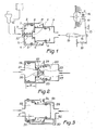
- a cylinder chamber 2 of the apparatus 1 with a larger cross section is connected via a pipeline to a cylinder 12 of a clutch pedal.
- a smaller cross-section having Direction cylinder space 3 is connected via a pipe with a working - area of the clutch releasing cylinder 13 work in conjunction.
- a stepped piston 4, 4 'moving in the cylinder spaces is sealed by sealing rings 5 and 6.
- the cylinder spaces 2 and 3 are connected to one another via a channel 7 which is guided through the stepped piston.
- the channel is closed by a valve 8 which is pressed against the step piston by a spring 9.
- a stop 10 At the other end of the valve stem guided in the housing there is a stop 10.
- the stepped piston is held in the basic position by a spring 11. The whole system is filled with liquid.
- a prescribed gap is provided - in the resting state of the system between a clutch bearings 16 and 17 of the clutch Aushebehebeln a pre-is.
- liquid flows from the cylinder 12 into the space 2 by pressing the clutch pedal and moves the stepped piston 4, 4 ', which the valve 8 follows.
- the stepped piston with the provisionally closed channel pushes the liquid out of the space 3 into the working cylinder 13, whereby, via the push rod 14 and the connecting lever 15, the clutch bearing 16 begins to disengage (disengage) the clutch.
- the gap a and the game between the transmitters disappear Divide, the actuator begins to be pressurized and the clutch is ready to disengage.
- the stepped piston moves further.
- the stepped piston leaves the valve 8 and the liquid flows out of the cylinder 12 through the channel 7 into the working cylinder, ie the clutch is released or disengaged.
- the both rooms 19 and 20 of the apparatus connected by two channels.
- the channel 21 is formed in a stepped piston 24 and is closed by the check valve 22, which has a weak spring 23, which releases the flow in the direction of the space 20.
- the channel 25 is formed in the check valve 22 and is closed by the check valve 26 which releases the flow into the space 19.
- the check valve 26 is held in the closed state by a prestressed spring 27.
- the channel 30 connecting the cylinder spaces 28 and 29 is connected to the corresponding cylinder space through openings 31 and 32 formed in the wall of the cylinders.
- the stepped piston 33 is held in its basic position by a spring 34.
- the function is similar to that already described.
- the channel 30 is after the exposure or hiding the Opening 31 opened or closed by the stepped piston itself.
- the gap a is proportional to the displacement between the basic position of the stepped piston and the opening of the opening 31, ie the section b ′′.
- valve shown in Fig. 2 can be installed in a channel according to Fig. 3.
- Cylinders and pistons do not necessarily have to be designed as stepped cylinders or stepped pistons. Two simple cylinders can also be used at any time.
- the dead game can be set automatically and kept at the prescribed value. Since the apparatus has no quickly wearing parts, its parameters do not change during use, i.e. the apparatus is more perfect than the previously known solutions.
- the apparatus can be designed as an independent unit and mounted on the control element of the hydraulic system or also on the working cylinder.
- the device can also be retrofitted into existing systems.
Landscapes
- Engineering & Computer Science (AREA)
- General Engineering & Computer Science (AREA)
- Mechanical Engineering (AREA)
- Hydraulic Clutches, Magnetic Clutches, Fluid Clutches, And Fluid Joints (AREA)
- Braking Arrangements (AREA)
- Pinball Game Machines (AREA)
- Tension Adjustment In Filamentary Materials (AREA)
- Devices For Conveying Motion By Means Of Endless Flexible Members (AREA)
- Fluid-Damping Devices (AREA)
- Massaging Devices (AREA)
- Soil Working Implements (AREA)
- Prostheses (AREA)
Priority Applications (1)
| Application Number | Priority Date | Filing Date | Title |
|---|---|---|---|
| AT80101684T ATE4607T1 (de) | 1979-04-05 | 1980-03-28 | Selbsttaetig wirkende einrichtung zum ein- und nachstellen des toten spiels einer hydraulisch betaetigten vorrichtung. |
Applications Claiming Priority (2)
| Application Number | Priority Date | Filing Date | Title |
|---|---|---|---|
| HU79CE1210A HU180810B (en) | 1979-04-05 | 1979-04-05 | Slack adjuster |
| HUCE001210 | 1979-04-05 |
Publications (2)
| Publication Number | Publication Date |
|---|---|
| EP0017194A1 true EP0017194A1 (fr) | 1980-10-15 |
| EP0017194B1 EP0017194B1 (fr) | 1983-09-07 |
Family
ID=10994270
Family Applications (1)
| Application Number | Title | Priority Date | Filing Date |
|---|---|---|---|
| EP80101684A Expired EP0017194B1 (fr) | 1979-04-05 | 1980-03-28 | Installation pour régler automatiquement le jeu d'un dispositif hydraulique |
Country Status (8)
| Country | Link |
|---|---|
| EP (1) | EP0017194B1 (fr) |
| AT (1) | ATE4607T1 (fr) |
| CS (1) | CS221537B2 (fr) |
| DD (1) | DD150099A5 (fr) |
| DE (1) | DE3064729D1 (fr) |
| HU (1) | HU180810B (fr) |
| PL (1) | PL123127B1 (fr) |
| RO (1) | RO88278B (fr) |
Cited By (4)
| Publication number | Priority date | Publication date | Assignee | Title |
|---|---|---|---|---|
| DE10151311A1 (de) * | 2001-10-17 | 2003-04-30 | Zahnradfabrik Friedrichshafen | Kupplung mit Verschleißkompensation |
| FR2927963A1 (fr) * | 2008-02-27 | 2009-08-28 | Renault Sas | Dispositif de commande de debrayage avec compensation d'usure de sa garniture de friction. |
| US8827062B2 (en) | 2010-08-04 | 2014-09-09 | Magna Powertrain Ag & Co Kg | Torque transmission unit |
| DE112013005392B4 (de) * | 2012-11-12 | 2020-01-02 | Schaeffler Technologies AG & Co. KG | Druckübersetzer für eine hydraulische Strecke zwischen einem Geberzylinder und einem Nehmerzylinder, insbesondere in Form eines deckelfesten Ausrückers |
Families Citing this family (3)
| Publication number | Priority date | Publication date | Assignee | Title |
|---|---|---|---|---|
| DE102007012491A1 (de) * | 2007-03-15 | 2008-09-18 | Magna Powertrain Ag & Co Kg | Lamellenkupplung |
| DE102014118270B3 (de) * | 2014-12-10 | 2016-05-12 | Knorr-Bremse Systeme für Nutzfahrzeuge GmbH | Pneumatische Kupplung mit Lagervorspannung |
| DE102015204673B3 (de) * | 2015-03-16 | 2016-07-21 | Schaeffler Technologies AG & Co. KG | Hydraulikanordnung für eine hydraulisch betätigte Reibkupplung und Verfahren zum Betätigen einer hydraulisch betätigten Reibkupplung |
Citations (10)
| Publication number | Priority date | Publication date | Assignee | Title |
|---|---|---|---|---|
| GB1038832A (en) * | 1963-04-08 | 1966-08-10 | Nat Res Dev | Power transmission apparatus |
| GB1071375A (en) * | 1964-07-10 | 1967-06-07 | Rech Etudes Prod | Servo-control devices |
| DE1289689B (de) * | 1967-01-26 | 1969-02-20 | Teves Gmbh Alfred | Selbsttaetige mechanische Nachstellvorrichtung fuer einen hydraulisch beaufschlagbaren Kolben |
| FR2038313A1 (fr) * | 1969-04-08 | 1971-01-08 | Paschke Hanns Dieter | |
| DE2140516B2 (de) * | 1970-08-24 | 1972-10-12 | Sab Brake Regulator Co. Ltd., Darlington, Durham (Grossbritannien) | Selbsttätige, axial wirkende Spielnachstell-Vorrichtung für Kupplungs-Ausrückgestänge |
| DE2256249A1 (de) * | 1971-12-08 | 1973-06-20 | Tatra Np | Vorrichtung zur hydraulischen steuerung einer kupplung |
| US3756361A (en) * | 1971-04-07 | 1973-09-04 | R Persson | Clutch-release linkage automatic axially-acting slack adjuster |
| HU169345B (fr) * | 1974-04-22 | 1976-11-28 | ||
| US4057135A (en) * | 1975-09-19 | 1977-11-08 | Aisin Seiki Kabushiki Kaisha | Self-adjusting release mechanism for a clutch assembly |
| US4057134A (en) * | 1976-05-28 | 1977-11-08 | Borg-Warner Corporation | Automatic clutch wear adjuster |
-
1979
- 1979-04-05 HU HU79CE1210A patent/HU180810B/hu not_active IP Right Cessation
-
1980
- 1980-03-11 PL PL1980222599A patent/PL123127B1/pl unknown
- 1980-03-20 CS CS801913A patent/CS221537B2/cs unknown
- 1980-03-26 RO RO100628A patent/RO88278B/ro unknown
- 1980-03-28 DE DE8080101684T patent/DE3064729D1/de not_active Expired
- 1980-03-28 AT AT80101684T patent/ATE4607T1/de not_active IP Right Cessation
- 1980-03-28 EP EP80101684A patent/EP0017194B1/fr not_active Expired
- 1980-04-01 DD DD80220131A patent/DD150099A5/de not_active IP Right Cessation
Patent Citations (10)
| Publication number | Priority date | Publication date | Assignee | Title |
|---|---|---|---|---|
| GB1038832A (en) * | 1963-04-08 | 1966-08-10 | Nat Res Dev | Power transmission apparatus |
| GB1071375A (en) * | 1964-07-10 | 1967-06-07 | Rech Etudes Prod | Servo-control devices |
| DE1289689B (de) * | 1967-01-26 | 1969-02-20 | Teves Gmbh Alfred | Selbsttaetige mechanische Nachstellvorrichtung fuer einen hydraulisch beaufschlagbaren Kolben |
| FR2038313A1 (fr) * | 1969-04-08 | 1971-01-08 | Paschke Hanns Dieter | |
| DE2140516B2 (de) * | 1970-08-24 | 1972-10-12 | Sab Brake Regulator Co. Ltd., Darlington, Durham (Grossbritannien) | Selbsttätige, axial wirkende Spielnachstell-Vorrichtung für Kupplungs-Ausrückgestänge |
| US3756361A (en) * | 1971-04-07 | 1973-09-04 | R Persson | Clutch-release linkage automatic axially-acting slack adjuster |
| DE2256249A1 (de) * | 1971-12-08 | 1973-06-20 | Tatra Np | Vorrichtung zur hydraulischen steuerung einer kupplung |
| HU169345B (fr) * | 1974-04-22 | 1976-11-28 | ||
| US4057135A (en) * | 1975-09-19 | 1977-11-08 | Aisin Seiki Kabushiki Kaisha | Self-adjusting release mechanism for a clutch assembly |
| US4057134A (en) * | 1976-05-28 | 1977-11-08 | Borg-Warner Corporation | Automatic clutch wear adjuster |
Cited By (4)
| Publication number | Priority date | Publication date | Assignee | Title |
|---|---|---|---|---|
| DE10151311A1 (de) * | 2001-10-17 | 2003-04-30 | Zahnradfabrik Friedrichshafen | Kupplung mit Verschleißkompensation |
| FR2927963A1 (fr) * | 2008-02-27 | 2009-08-28 | Renault Sas | Dispositif de commande de debrayage avec compensation d'usure de sa garniture de friction. |
| US8827062B2 (en) | 2010-08-04 | 2014-09-09 | Magna Powertrain Ag & Co Kg | Torque transmission unit |
| DE112013005392B4 (de) * | 2012-11-12 | 2020-01-02 | Schaeffler Technologies AG & Co. KG | Druckübersetzer für eine hydraulische Strecke zwischen einem Geberzylinder und einem Nehmerzylinder, insbesondere in Form eines deckelfesten Ausrückers |
Also Published As
| Publication number | Publication date |
|---|---|
| EP0017194B1 (fr) | 1983-09-07 |
| CS221537B2 (en) | 1983-04-29 |
| ATE4607T1 (de) | 1983-09-15 |
| DD150099A5 (de) | 1981-08-12 |
| RO88278B (ro) | 1985-12-31 |
| PL222599A1 (fr) | 1980-12-01 |
| PL123127B1 (en) | 1982-09-30 |
| DE3064729D1 (en) | 1983-10-13 |
| RO88278A (fr) | 1985-12-30 |
| HU180810B (en) | 1983-04-29 |
Similar Documents
| Publication | Publication Date | Title |
|---|---|---|
| DE69125388T2 (de) | Automatische kontrollevorrichtung | |
| DE2362350C2 (de) | Hauptzylinder für zwei getrennte hydraulische Kreise | |
| DE69208207T2 (de) | Rotorbremse-Einheit eines Drehflügelflugzeuges | |
| DE2316594B2 (de) | Be- und Entlüftungssystem für die Federkammer eines Tandem-Federspeicherund Betriebszylinders | |
| DE1916266A1 (de) | Elektrohydraulisches Stellgeraet | |
| DE102011108649B4 (de) | Drehmomentübertragungseinheit | |
| EP0031057B1 (fr) | Cylindre d'accumulateur à ressort pour frein | |
| DE3821700C2 (fr) | ||
| DE3235001A1 (de) | Pneumatische schalteinrichtung | |
| EP0017194B1 (fr) | Installation pour régler automatiquement le jeu d'un dispositif hydraulique | |
| DE2842736C3 (de) | Kupplungsbetätigte Schallsperre für druckmittelbetätigte Schaltgetriebe, insbesondere für Kraftfahrzeuge | |
| DE2416104C3 (de) | Stromregelventil | |
| DE645823C (de) | Pneumatische Schliessvorrichtung fuer Tueren, insbesondere in Eisenbahnwagen | |
| DE4444841C2 (de) | Hydraulische Betätigungseinrichtung mit einem Geberzylinder und einem Nehmerzylinder | |
| DE1425355A1 (de) | Hilfsvorrichtung zum Ausruecken von Kupplungen | |
| DE2164160C3 (de) | Hydraulischer Hauptzyliner | |
| DE2033614A1 (de) | Betatigungsghed fur Steuerventile | |
| DE2112764C3 (de) | Zweidrucksteuerventil für einstufig zu lösende selbsttätige Druckmittelbremsanlagen, insbesondere für Schienenfahrzeuge | |
| EP2131001A2 (fr) | Amortisseur de fermeture de porte | |
| DE3607063A1 (de) | Steuerventil fuer doppelwirkende pneumatische arbeitszylinder | |
| DE1193744B (de) | Selbsttaetige Steuerungsanlage fuer eine durch Fluessigkeitsdruck betaetigte Reibungskupplung zur Bewerkstelligung von Kupplungsschaltvorgaengen bzw. UEberbrueckungsvorgaengen bei Getrieben mit hydrodynamischem Kreislauf | |
| DE2102142C3 (de) | Blockiergeschützte Fahrzeugbremsanlage | |
| DE3104286C2 (fr) | ||
| DE2514593B2 (de) | Steuerventil für hydraulisch betätigte Lamellen-Kupplungen | |
| DE1580046C3 (de) | Steuervorrichtung für ein durch druckmittelbetätigte Schaltmittel unter Last schaltbares Wechsel- und Wendegetriebe |
Legal Events
| Date | Code | Title | Description |
|---|---|---|---|
| PUAI | Public reference made under article 153(3) epc to a published international application that has entered the european phase |
Free format text: ORIGINAL CODE: 0009012 |
|
| AK | Designated contracting states |
Designated state(s): AT DE FR GB IT SE |
|
| 17P | Request for examination filed |
Effective date: 19801029 |
|
| ITF | It: translation for a ep patent filed | ||
| GRAA | (expected) grant |
Free format text: ORIGINAL CODE: 0009210 |
|
| AK | Designated contracting states |
Designated state(s): AT DE FR GB IT SE |
|
| REF | Corresponds to: |
Ref document number: 4607 Country of ref document: AT Date of ref document: 19830915 Kind code of ref document: T |
|
| REF | Corresponds to: |
Ref document number: 3064729 Country of ref document: DE Date of ref document: 19831013 |
|
| ET | Fr: translation filed | ||
| PLBE | No opposition filed within time limit |
Free format text: ORIGINAL CODE: 0009261 |
|
| STAA | Information on the status of an ep patent application or granted ep patent |
Free format text: STATUS: NO OPPOSITION FILED WITHIN TIME LIMIT |
|
| 26N | No opposition filed | ||
| PGFP | Annual fee paid to national office [announced via postgrant information from national office to epo] |
Ref country code: FR Payment date: 19910222 Year of fee payment: 12 |
|
| PGFP | Annual fee paid to national office [announced via postgrant information from national office to epo] |
Ref country code: GB Payment date: 19910319 Year of fee payment: 12 |
|
| PGFP | Annual fee paid to national office [announced via postgrant information from national office to epo] |
Ref country code: AT Payment date: 19910324 Year of fee payment: 12 |
|
| ITTA | It: last paid annual fee | ||
| PGFP | Annual fee paid to national office [announced via postgrant information from national office to epo] |
Ref country code: DE Payment date: 19910411 Year of fee payment: 12 |
|
| PG25 | Lapsed in a contracting state [announced via postgrant information from national office to epo] |
Ref country code: GB Effective date: 19920328 Ref country code: AT Effective date: 19920328 |
|
| PGFP | Annual fee paid to national office [announced via postgrant information from national office to epo] |
Ref country code: SE Payment date: 19920930 Year of fee payment: 13 |
|
| GBPC | Gb: european patent ceased through non-payment of renewal fee | ||
| PG25 | Lapsed in a contracting state [announced via postgrant information from national office to epo] |
Ref country code: FR Effective date: 19921130 |
|
| PG25 | Lapsed in a contracting state [announced via postgrant information from national office to epo] |
Ref country code: DE Effective date: 19921201 |
|
| REG | Reference to a national code |
Ref country code: FR Ref legal event code: ST |
|
| PG25 | Lapsed in a contracting state [announced via postgrant information from national office to epo] |
Ref country code: SE Effective date: 19930329 |
|
| EUG | Se: european patent has lapsed |
Ref document number: 80101684.1 Effective date: 19931008 |