EP0017247A2 - Dispositif de commutation - Google Patents
Dispositif de commutation Download PDFInfo
- Publication number
- EP0017247A2 EP0017247A2 EP80101833A EP80101833A EP0017247A2 EP 0017247 A2 EP0017247 A2 EP 0017247A2 EP 80101833 A EP80101833 A EP 80101833A EP 80101833 A EP80101833 A EP 80101833A EP 0017247 A2 EP0017247 A2 EP 0017247A2
- Authority
- EP
- European Patent Office
- Prior art keywords
- current
- diode
- series
- conductors
- consumers
- Prior art date
- Legal status (The legal status is an assumption and is not a legal conclusion. Google has not performed a legal analysis and makes no representation as to the accuracy of the status listed.)
- Ceased
Links
- 239000004020 conductor Substances 0.000 claims abstract description 25
- 230000009467 reduction Effects 0.000 description 7
- 230000004913 activation Effects 0.000 description 3
- 238000009434 installation Methods 0.000 description 3
- 230000004048 modification Effects 0.000 description 2
- 238000012986 modification Methods 0.000 description 2
- 238000010276 construction Methods 0.000 description 1
- 238000010616 electrical installation Methods 0.000 description 1
- 230000005611 electricity Effects 0.000 description 1
Images
Classifications
-
- H—ELECTRICITY
- H05—ELECTRIC TECHNIQUES NOT OTHERWISE PROVIDED FOR
- H05B—ELECTRIC HEATING; ELECTRIC LIGHT SOURCES NOT OTHERWISE PROVIDED FOR; CIRCUIT ARRANGEMENTS FOR ELECTRIC LIGHT SOURCES, IN GENERAL
- H05B47/00—Circuit arrangements for operating light sources in general, i.e. where the type of light source is not relevant
- H05B47/10—Controlling the light source
Definitions
- the invention relates to an AC switch for individually switching on at least two universal currents. r-users, for whose power supply there are only two current conductors.
- a circuit is known to alternatively or simultaneously switch on two consumers, for whose power supply there are only two current conductors.
- the two consumers are each connected in series with a converter, the two converters having opposite poles.
- the alternative switching on of the two consumers then takes place in such a way that the alternating current rectified by the converter is reversed.
- the polarity reversal is done by two opposing power converters, which can be alternately connected to the cables if required.
- the simultaneous activation takes place in that alternating current is applied to both consumers.
- the previously known circuit however, there is the disadvantage that the effective AC input voltage is reduced, which, for. B. in lightbulbs causes a drop not only the brightness, but also the light efficiency, and that the direct current generated has a large ripple.
- the large ripple causes lightbulbs as all-current consumers to flicker in brightness, which is unbearable in the long run.
- the invention has for its object to avoid the disadvantages of the known circuit and to create a circuit which provides the respective all-current consumer with the same effective voltage and a comparable current quality as is the case with the primary AC network.
- the invention is based on a known AC switch for separately switching on at least two universal power consumers, for the power supply of which there are only two current conductors.
- the invention consists of a two-way rectifier with a downstream pole changer, the successive activation of the first all-current consumer being directly connected to the current conductors and the second all-current consumer being connected to the current conductors by means of a diode connected in series or, alternatively, the first all-current consumer being connected in series by a diode and the an opposing diode in series connected second all-current consumers are connected to the current conductors.
- the all-current consumer receives the full effective voltage and consequently also the full power. In addition, the voltage is much less rippled than is the case with one-way rectification.
- this consists of two all-current consumers connected in series, the first connection piece directly with the first current conductor, the connection piece with the base of a first diode connected to the second current conductor, the second connection piece with the emitters of a second and a third diode, the base of the second diode is connected to the second current conductor and the base of the third diode is again connected to the first current conductor.
- This circuit enables the two all-current consumers to be connected either in series or in parallel.
- Light bulbs or groups of light bulbs are preferably provided as all-current consumers.
- the invention relates to an AC switch for individually switching on at least two AC consumers A, B, for their power supply only two Current conductors 5 a, 5 b are present.
- all-current consumers A, B are primarily considered to be light bulbs or groups of light bulbs. However, it goes without saying that other universal electricity consumers can also take the place of the light bulbs or groups of light bulbs. It is also readily apparent that if only light bulbs are mentioned below, this also includes light bulb groups or other all-current consumers.
- Installations are carried out correctly with three conductors, two of which are used for power supply and one for earthing.
- the earth conductor but also out of consideration below, since it must not be used for switching purposes.
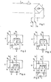
- the invention provides a two-way rectifier bridge 3, in front of which an on-off switch is connected.
- a fuse 2 can also be provided between switch 1 and rectifier 3. The use of a two-way rectifier 3 ensures that both half-waves of the alternating current are used and that the effective voltage and thus also the power of the direct current generated matches the alternating current.
- the circuit After the rectifier bridge 3, the circuit provides a pole changer 4 with which it is possible to reverse the polarity of the direct current in the two connecting lines 5 a, 5 b as desired.
- the lines 5 a, 5 b establish the connection with a distributor 6; it can be, for example, the lines of a domestic installation that run between a switch and a ceiling lamp.
- the distributor 6 has two input pieces 6 a, 6 b and four output pieces 6 c, 6 d, 6 e and 6 f. Between the input piece 6 b and the output piece 6 d is a diode 7, which is connected with its emitter to the input piece 6 b. A second diode 8 is connected with its base to the input piece 6 b and with its emitter to the output piece 6 f. The input piece 6 a is directly connected to the output piece 6 c by a bridge.
- Figure 2 shows a circuit for the simultaneous or the successive switching on of two light bulbs A and B.
- the light bulb A is connected to the output pieces 6 c, 6 e and the light bulb B to the output pieces 6 c, 6 f.
- the light bulb A burns in both switching positions of the pole changer 4, while the light bulb B burns only in one switching position of the pole changer 4, and specifically when the minus fol is on the input piece 6 a. If the current is reversed, the current flow from the diode 8 through the light bulb B is interrupted.
- Figure 3 shows a circuit for the alternative. Switching on two light bulbs A and B. This is the light bulb. A with the output pieces 6 c, 6 d and the light bulb B with the output pieces 6 c, 6 f of the same distributor 6. In this case, the two light bulbs A, B can alternatively be switched on with the two switching positions of the pole changer 4. An additional light bulb, which is connected to the connectors 6 c, 6 e, burns in both switching positions of the pole changer.
- FIGS. 4 and 5 show a distributor 10 as a modification of the distributor 6.
- the output piece 6 f are connected to the emitter of a third diode 9 and the base thereof is connected to the input piece 6 a.
- the distributor 10 according to FIGS. 4 and 5 offers the possibility of connecting two light bulbs A, B to the direct current by switching the pole reverser 4 either in series or in parallel.
- a light bulb C is connected which is at the full effective voltage when the positive pole is connected to the connecting piece 6b, that is to say when A and B are connected in series switched off and A and B are parallel at full voltage and burn with full brightness.
- the distributor 10 in FIGS. 4 and 5 can additionally fulfill the function of the distributor 6 in FIGS. 2 and 3.
- Got the light bulb NEN A, B in Figure 4 the same power, the brightness when switching the Pölwender 4 and thus switching from parallel to series connection is reduced by about a factor of 14. With different power of the light bulbs A, B it is this factor smaller. If you switch on the light bulbs first via the series connection and only then switch over to the parallel connection, this prevents the high inrush currents that are more than a factor of 10 above the operating current, which increases the life of the light bulbs.
- a light bulb C for example a spotlight
- a light bulb C can be connected, which only burns when light bulbs A, B burn as main bulbs with a reduced brightness.
- the circuits according to the invention can be used in all households in which the electrical installation for lighting is carried out in a simple form with only two lines.
- the main switch 1, the rectifier bridge 3 and the pole changer 4 can be combined in the size of a conventional Unterputsachalters manufactured and installed instead of the usual light switch.
- the distributor 6 or 10 can be created at the connection point of the lamp with two or three diodes in a sufficiently small dimension. It can be installed instead of the usual connector to the lamp.
- diodes in the form of platelets in the bulb socket in lamps which do not have the wiring required for the individual switching of two light bulbs to attach them to the bottom of the bulb or in the bulb socket or in the bulb itself to be installed so that they correspond de Light bulb burns only in one of the two current directions.
- the other light bulbs can be provided with a reversely oriented diode, so they burn in the other current direction, or cannot be provided with a diode and then burn in both current directions.
- a further application of the invention results from the construction of light bulbs with two filaments of different power, the filament with the higher power in the light bulb being connected in series to form a diode.
- the higher power can be switched off by reversing the current through the pole changer 4, and the only thing that burns is the filament with the lower power.
- the filament with the lower power is also connected in series to a diode that is opposite to the first diode, both filaments can alternatively be switched on.
- the filament with the lower power is due to the full effective voltage and that it does not have a reduced temperature, as is the case with the twilight circuit. With the same brightness, the efficiency of the light bulb is both. Circuit according to the invention several times higher than that of the dimmer circuit, and the power consumption is correspondingly lower.
- connections of the two filaments can be led out of the light bulb in the usual way, and the required diodes are then installed in a correspondingly constructed socket or the connections are led to one of the distributors 6 and 10 described above.
Landscapes
- Circuit Arrangement For Electric Light Sources In General (AREA)
- Keying Circuit Devices (AREA)
Applications Claiming Priority (2)
| Application Number | Priority Date | Filing Date | Title |
|---|---|---|---|
| DE2914441 | 1979-04-10 | ||
| DE19792914441 DE2914441A1 (de) | 1979-04-10 | 1979-04-10 | Wechselstromschalter |
Publications (2)
| Publication Number | Publication Date |
|---|---|
| EP0017247A2 true EP0017247A2 (fr) | 1980-10-15 |
| EP0017247A3 EP0017247A3 (fr) | 1980-10-29 |
Family
ID=6067951
Family Applications (1)
| Application Number | Title | Priority Date | Filing Date |
|---|---|---|---|
| EP80101833A Ceased EP0017247A3 (fr) | 1979-04-10 | 1980-04-05 | Dispositif de commutation |
Country Status (2)
| Country | Link |
|---|---|
| EP (1) | EP0017247A3 (fr) |
| DE (1) | DE2914441A1 (fr) |
Cited By (3)
| Publication number | Priority date | Publication date | Assignee | Title |
|---|---|---|---|---|
| GB2117578A (en) * | 1982-03-26 | 1983-10-12 | American Sterilizer Co | Controller for lamp having more than one light source |
| GB2128043A (en) * | 1982-09-28 | 1984-04-18 | Gen Electric | Dual load remote power control |
| DE4016482A1 (de) * | 1990-05-22 | 1991-11-28 | Siemens Ag | Schaltung zum wahlweisen betrieb jeweils einer vielzahl gemeinsam betreibbarer erster lampen und einer vielzahl gemeinsam beteibbarer zweiter lampen |
Families Citing this family (2)
| Publication number | Priority date | Publication date | Assignee | Title |
|---|---|---|---|---|
| DE102008011065A1 (de) * | 2008-02-26 | 2009-08-27 | Osram Gesellschaft mit beschränkter Haftung | Startverfahren zur Verbesserung der Lebensdauer einer Glühlampe und Glühlampe mit erhöhter Lebensdauer |
| DE202019105046U1 (de) * | 2019-09-12 | 2020-12-16 | Wilhelm Koch Gmbh | Beleuchtungsanordnung |
Family Cites Families (2)
| Publication number | Priority date | Publication date | Assignee | Title |
|---|---|---|---|---|
| US3454826A (en) * | 1967-05-05 | 1969-07-08 | Bell Telephone Labor Inc | Polarized dual lamp unit with polarizing diodes |
| US3530501A (en) * | 1968-12-11 | 1970-09-22 | Oak Electro Netics Corp | Plural visual indicator assembly energizable through two input terminals |
-
1979
- 1979-04-10 DE DE19792914441 patent/DE2914441A1/de not_active Withdrawn
-
1980
- 1980-04-05 EP EP80101833A patent/EP0017247A3/fr not_active Ceased
Cited By (3)
| Publication number | Priority date | Publication date | Assignee | Title |
|---|---|---|---|---|
| GB2117578A (en) * | 1982-03-26 | 1983-10-12 | American Sterilizer Co | Controller for lamp having more than one light source |
| GB2128043A (en) * | 1982-09-28 | 1984-04-18 | Gen Electric | Dual load remote power control |
| DE4016482A1 (de) * | 1990-05-22 | 1991-11-28 | Siemens Ag | Schaltung zum wahlweisen betrieb jeweils einer vielzahl gemeinsam betreibbarer erster lampen und einer vielzahl gemeinsam beteibbarer zweiter lampen |
Also Published As
| Publication number | Publication date |
|---|---|
| EP0017247A3 (fr) | 1980-10-29 |
| DE2914441A1 (de) | 1980-10-16 |
Similar Documents
| Publication | Publication Date | Title |
|---|---|---|
| DE202013000064U1 (de) | LED-Anordnung | |
| EP0488002A1 (fr) | Procédé et dispositif de commande de tubes à décharge par l'intermédiaire de ballasts électroniques | |
| DE9307862U1 (de) | Leuchtkörper für Leuchtreklamen | |
| EP0017247A2 (fr) | Dispositif de commutation | |
| EP2282610B1 (fr) | Procédé de commande d'une lampe | |
| DE3417194C2 (fr) | ||
| DE1952697B2 (de) | Vorrichtung zur elektronischen zuendung von gasentladungslampen | |
| DE19723617A1 (de) | Beleuchtungsanlage für Straßen, Plätze und Objekte | |
| DE102009035169A1 (de) | Verfahren zur Einstellung der Ansteuerung mehrerer Leuchten | |
| EP0374724A1 (fr) | Rail d'alimentation pour appareil d'éclairage | |
| DE20101295U1 (de) | Beleuchtungseinrichtung zum Betrieb an einem Wechselstromnetz | |
| DE9014982U1 (de) | Dimmbare Leuchtenanordnung | |
| DE202013104307U1 (de) | LEDs auf Platinenstreifen | |
| DE19830271A1 (de) | Beleuchtungseinrichtung in Modulbauweise | |
| DE202017106583U1 (de) | Nahtlose Verbindung ermöglichende rechteckige LED-Leuchte, bei der die Kabel verborgen bleiben | |
| DE19842761A1 (de) | Verfahren zum tageslichtabhängigen Dimmen von mehrflammigen Leuchten | |
| DE8408553U1 (de) | Lampensockel für eine elektrische Lampe mit zwei Glühbirnen | |
| DE2029050A1 (de) | Anordnung zum Abblenden mindestens zweier parallel geschalteter Entladungs lampen | |
| DE102005059612B4 (de) | Straßenbeleuchtungssystem mit Schalteinrichtung und ein- und mehrflammigen Leuchten | |
| DE3716310C1 (en) | Arrangement for operating low-voltage loads | |
| DE38880C (de) | System der elektrischen Stromvertheilung mittelst Volta-Induktoren | |
| DE908042C (de) | Entladelampen-Stromkreis | |
| DE212010000180U1 (de) | Eine zusammengesetzte LED-Lampe | |
| DE60036274T2 (de) | Gerät zur Reduzierung der in den Versorgungsleitungen zerstreuten Leistung in Beleuchtungsanlagen | |
| DE94899C (fr) |
Legal Events
| Date | Code | Title | Description |
|---|---|---|---|
| PUAI | Public reference made under article 153(3) epc to a published international application that has entered the european phase |
Free format text: ORIGINAL CODE: 0009012 |
|
| PUAL | Search report despatched |
Free format text: ORIGINAL CODE: 0009013 |
|
| AK | Designated contracting states |
Designated state(s): AT BE CH FR GB IT LU NL SE |
|
| AK | Designated contracting states |
Designated state(s): AT BE CH FR GB IT LU NL SE |
|
| 17P | Request for examination filed |
Effective date: 19810424 |
|
| STAA | Information on the status of an ep patent application or granted ep patent |
Free format text: STATUS: THE APPLICATION HAS BEEN REFUSED |
|
| 18R | Application refused |
Effective date: 19830801 |