EP0017319A2 - Connecteur de cable optique pour boîtiers étanches - Google Patents
Connecteur de cable optique pour boîtiers étanches Download PDFInfo
- Publication number
- EP0017319A2 EP0017319A2 EP80300411A EP80300411A EP0017319A2 EP 0017319 A2 EP0017319 A2 EP 0017319A2 EP 80300411 A EP80300411 A EP 80300411A EP 80300411 A EP80300411 A EP 80300411A EP 0017319 A2 EP0017319 A2 EP 0017319A2
- Authority
- EP
- European Patent Office
- Prior art keywords
- cable
- fibre
- connector
- wall
- housing
- Prior art date
- Legal status (The legal status is an assumption and is not a legal conclusion. Google has not performed a legal analysis and makes no representation as to the accuracy of the status listed.)
- Granted
Links
Images


Classifications
-
- G—PHYSICS
- G02—OPTICS
- G02B—OPTICAL ELEMENTS, SYSTEMS OR APPARATUS
- G02B6/00—Light guides; Structural details of arrangements comprising light guides and other optical elements, e.g. couplings
- G02B6/44—Mechanical structures for providing tensile strength and external protection for fibres, e.g. optical transmission cables
- G02B6/4401—Optical cables
- G02B6/4415—Cables for special applications
- G02B6/4427—Pressure resistant cables, e.g. undersea cables
- G02B6/4428—Penetrator systems in pressure-resistant devices
-
- G—PHYSICS
- G02—OPTICS
- G02B—OPTICAL ELEMENTS, SYSTEMS OR APPARATUS
- G02B6/00—Light guides; Structural details of arrangements comprising light guides and other optical elements, e.g. couplings
- G02B6/24—Coupling light guides
- G02B6/36—Mechanical coupling means
- G02B6/38—Mechanical coupling means having fibre to fibre mating means
- G02B6/3807—Dismountable connectors, i.e. comprising plugs
- G02B6/3887—Anchoring optical cables to connector housings, e.g. strain relief features
- G02B6/3888—Protection from over-extension or over-compression
-
- G—PHYSICS
- G02—OPTICS
- G02B—OPTICAL ELEMENTS, SYSTEMS OR APPARATUS
- G02B6/00—Light guides; Structural details of arrangements comprising light guides and other optical elements, e.g. couplings
- G02B6/24—Coupling light guides
- G02B6/36—Mechanical coupling means
- G02B6/38—Mechanical coupling means having fibre to fibre mating means
- G02B6/3807—Dismountable connectors, i.e. comprising plugs
- G02B6/3887—Anchoring optical cables to connector housings, e.g. strain relief features
- G02B6/3889—Anchoring optical cables to connector housings, e.g. strain relief features using encapsulation for protection, e.g. adhesive, molding or casting resin
Definitions
- the invention relates to a connector for connecting a cable containing one or more optical fibres to a hollow member, such as a repeater box in an optical communications system, the cable and the hollow member being sealed and perhaps, slightly pressurized to prevent the ingress of dirt and moisture.
- optical fibres in communication systems and optical fibres still need to use repeater boxes to amplify the signals passing through the fibres although usually at greater distances apart than with the electrical type. It is still desirable that the cables containing the optical fibres and the repeater boxes are within the diaphragm, and guide means are provided between the diaphragm and the cable whereby the or each optical fibre can be withdrawn and replaced without dismantling the housing.
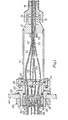
- the connector consists of a cylindrical body 10, to one end of which is secured a collar 12.
- the collar 12 is formed with a screw thread on which is mounted a nut 14, and located within the separately sealed to prevent the ingress of moisture, dirt etc since optical fibres can be damaged by water, particularly if it freezes.
- the well known method of sealing the ends of cables carrying electrical conductors cannot be used since optical fibres are quite delicate and can only withstand low bending and tensile stresses, whereas electrical conductors can readily withstand quite high tensile and bending stresses which these connectors can impose.
- Co unication cables also usually contain a fairly large number of electrical conductors and so it is not too important if one of the conductors is broken. Only a small number of optical fibres are contained inside an optical communications cable and if one breaks it is useful if it can be readily replaced.
- the invention as claimed is intended to remedy these problems by providing a housing sealingly connected to the end of the cable, the housing having a diaphragm through which the optical fibres pass, each fibre being sealed to the diaphragm whereby the housing is hermetically sealed, and strain means connecting the cable and the housing to prevent the optical fibres from being subjected to stress and/or strain.
- a resilient grommet 16 which is intended to grip an optical cable 18.
- a flange member 20 To the other dnd of the cylindrical body 10 is bolted a flange member 20 and rigidly clamped between the body 10 and the flange member 20 is a strain bar 22.
- a resilient '0' ring 24 between the body 10 and the flange member 20 seals this joint.
- Bolted inside the flange member 20 by a nut 26 is a diaphragm 28, again with an '0' ring 30 to seal the joiht.
- the diaphragm 28 is provided with four sleeves 32, (only two of which are shown in FIGURE 1), each sleeve being provided with a projection 34 which extends through the diaphragm 28, and each sleeve 32 being provided with a fine hole 36 which also extends through the projection 34.
- sleeves 32 are provided with four sleeves 32, (only two of which are shown in FIGURE 1), each sleeve being provided with a projection 34 which extends through the diaphragm 28, and each sleeve 32 being provided with a fine hole 36 which also extends through the projection 34.
- One of these sleeves and part of the diaphragm 28 is shown in more detail if FIGURE 2 .
- the diaphragm 28 also has formed through it four further holes through which metal conductors 38 pass, these conductors being located in the diaphragm by glass-to-metal seals.
- a strut 40 is also secured to the outside surface of the diaphragm 28 which serves as a strain reliever for electrical wires mentioned hereinafter.
- the connector assembly is intended to be secured to a repeater box, a side 42 only of the repeater box being shown, and for this purpose tile flange member 20 is provided with an external screw thread so that the connector assembly can be bolted to the side 42 by means of a nut 44 inside the repeater box.
- a further '0' ring 46 seals the joint between the side 42 and the flange member 20.
- the optial cable 18 consists of a central high tensile steel strain wire 48 around which are arranged four tubes 50 each carrying a single filament optical fibre 52. In between the four tubes 50 are four insulated copper wires 54 for supervisory electrical signals. Surrounding the parts 48, 50 and 54 is a tubular extension of polythylene and then a helical band of kraft paper followed by an aluminium foil wrapped and continuously welded to form a water barrier known in the art as the "Glover Barrier". Finally an external tube of polyethylene is extruded to form the outer sheath of the cable.
- the end of the cable 18 is stripped of the outer sheath and the Glover Barrier for a length sufficient to permit the optical fibres to pass through the nut 14 and the collar 12, and a flange 56 is formed on the end of the polyethylene outer sheath of the cable 18.
- the flange 56 is preferably made from an epoxy resin moulded in position on the outer sheath of the cable 18 and prevents the cable from being pulled out of the connector.
- the nut 14 is tightened to barrel the grommet 16 and form a pressure-tight seal between the connector and the cable.
- the strain wire 48 is terminated adjacent to the strain bar 22 and clamped thereto by a screw 58.
- the copper wires 54 are separated from the tubes 5 0 and these are all fed past the strain bar 22 to the diaphragm 28.
- the optical filaments are fed through the fine holes 36 through the sleeves 32 and bonded into the sleeves by an epoxy resin seal 60.
- the tubes 50 are terminated adjacent to end ends of the project,ions 34 and sealed thereto using a length of heat shrink tubing 62.
- the copper wires 54 are soldered on to the projecting ends of the metal conductors 38.
- each of the optical fibres 52 are sleeved with a special cable 64 with a nylon inner tube 68 and three "Kevlar" (Registered Trade Mark) strain filaments 66 which are spaced at 120 degrees intervals around the nylon tube and are bonded to a polypropylene outer jacket 70.
- the cable 64 is mechanically anchored to the diaphragm 28 so that the external strains imposed in handling the cables 64 are not transmitted to the optical filaments 52.
- the mechanical anchorage consists of a clip 72 crimped tightly around the cable 64, a short metal sleeve 74 inside the cable 64 preventing collapse of the cable during the crimping operation.
- Lugs 76 are formed on the clip 72 during the crimping operation, and these are adapted to fit into axial slots 78 formed in each of the sleeves 32. Fins 80 fitted into holes 82 formed through the sleeve 32 at the ends of the slots 78 hold the lugs, and hence the cable 64 in position to withstand tensile and rotative forces on the cable 64. The end of the cable 64, and the sleeve 32 are finally covered with a length of heat shrink tube 84 to seal the joint and to help to retain the pins 80.
- Further conductive wires 86 are soldered to the outer ends of the metal conductors 38 and these are anchored to the strut 40 by suitable clips 88 to prevent strain on the joints between the further conductive wires 86 and the metal conductors 38.
- the connector is completely sealed against the ingress of dirt and moisture and as a further precaution the cable 18 and the interior of the body 10 in use is pressurized to about 8 p.s.i. Furthermore the optical fibres are protected from strain both sides of the diaphragm 28.
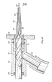
- the connector must be removed from the repeater box and the outer cable 64 removed from the broken fibre. Any fibre 52 projecting from the sleeve 32 is broken off and an adapted 90 fitted over the end of the sleeve 32.
- a suitable sized drill 92 is used to drill out the-epoxy resin seal 60 whilst a vacuum pump (not shown) draws away the debris through a sidepipe 94 forming part of the adaptor.
- Resilient 1 0 1 rings 94 and 98 seal the adaptor to the drill shank and the sleeve 32 respectively whilst the epoxy resin seal 60 is drilled out.
- the fibre 52 can be drawn out, and a replacement fibre fed up through the cable 18 and through the sleeve 32.
- a new epoxy resin seal 60 is made, and the cable 64 and its anchorage reassembled.
- the end of the fine hole 36 is countersunk.
- FIGURES 5 to 9 illustrate different methods of sealing the fibres 52 to the diarhragm 28, although in these cases the fibres are not removable without dismantling the connector.
- FIGURE 5 shows a cross-section of a fibre 52 which has been electroplated with a continuous metallic coating 100.
- the fibre 52 is pushed through a tube 102 which forms part of a glass-to-metal seal consisting of an annular glass or ceramic insulator 104 and a metallic housing 106.
- a hermetic seal is formed between the diaphragm 28 and the housing 106 by solder 108 and between the coating 100 and the tube 102 by solder 110.
- the coating 100 is electrically conductive and could be used instead of the copper wires 54.
- the optical fibre 52 has a local electroplated metallic coating 112, and the fibre is pushed through a hole in the diaphragm 28 and sealed with solder 113.
- FIGURE 7 illustrate a diaphragm 28 formed with a sleeve 114 which is thermo melted by direct heat and pressure ultrasonic means to form a hermetic seal as shown in FIGURE 8.
- This method can be used with the optical filaments 52 and the copper wires 54 and in this case the diaphragm 28 and the sleeve 114 can be moulded in a suitable plastics material.
- the optical fibre 52 passes through the diaphragm 28 which is threaded to accept a body 114 and an '0' ring seal 118 is compressed when the body 116 is screwed home.
- the body 116 could alternatively be soldered on to the diaphragm 28, or it could be moulded from a suitable plastic material integrally with the diaphragm 28 as in FIGURE 7.
- the tube 50 is crimped by a collar 120 to a sleeve screw 122 which is screwed to the body 116.
- a moulded elastomeric cone grommet 124 is compressed on to the fibre 52 as the sleeve screw 122 is tightened, thus making a hermetic seal.
Landscapes
- Physics & Mathematics (AREA)
- General Physics & Mathematics (AREA)
- Optics & Photonics (AREA)
- Mechanical Coupling Of Light Guides (AREA)
Applications Claiming Priority (2)
| Application Number | Priority Date | Filing Date | Title |
|---|---|---|---|
| GB7906959 | 1979-02-27 | ||
| GB7906959 | 1979-02-27 |
Publications (3)
| Publication Number | Publication Date |
|---|---|
| EP0017319A2 true EP0017319A2 (fr) | 1980-10-15 |
| EP0017319A3 EP0017319A3 (en) | 1981-01-07 |
| EP0017319B1 EP0017319B1 (fr) | 1982-12-29 |
Family
ID=10503480
Family Applications (1)
| Application Number | Title | Priority Date | Filing Date |
|---|---|---|---|
| EP80300411A Expired EP0017319B1 (fr) | 1979-02-27 | 1980-02-13 | Connecteur de cable optique pour boîtiers étanches |
Country Status (12)
| Country | Link |
|---|---|
| US (1) | US4312563A (fr) |
| EP (1) | EP0017319B1 (fr) |
| JP (1) | JPS55117116A (fr) |
| AU (1) | AU533932B2 (fr) |
| BR (1) | BR8001120A (fr) |
| CA (1) | CA1131726A (fr) |
| DE (1) | DE3061465D1 (fr) |
| GB (1) | GB2043943B (fr) |
| IE (1) | IE49416B1 (fr) |
| NZ (1) | NZ192880A (fr) |
| PT (1) | PT70861A (fr) |
| ZA (1) | ZA801037B (fr) |
Cited By (8)
| Publication number | Priority date | Publication date | Assignee | Title |
|---|---|---|---|---|
| WO1985002269A1 (fr) * | 1983-11-17 | 1985-05-23 | British Telecommunications Plc | Agencement de jointement |
| FR2585139A1 (fr) * | 1985-07-17 | 1987-01-23 | Lignes Telegraph Telephon | Tete d'eclatement d'un cable a fibres optiques en faisceaux de fibres ou en fibres |
| FR2587126A1 (fr) * | 1985-09-09 | 1987-03-13 | Lignes Telegraph Telephon | Dispositif d'eclatement d'un faisceau de fibres optiques en fibres optiques unitaires |
| FR2588670A1 (fr) * | 1985-10-16 | 1987-04-17 | Lignes Telegraph Telephon | Tete d'eclatement d'un cable a fibres optiques |
| FR2614433A1 (fr) * | 1987-04-21 | 1988-10-28 | Preformed Line Products Co | Enceinte pour l'enrobage d'un cable a fibre optique et procede d'enrobage d'un tel cable |
| EP0301380A3 (fr) * | 1987-07-27 | 1990-03-07 | PIRELLI CAVI S.p.A. | Ligne de télécommunications sous-marine à fibres optiques |
| EP0409390A3 (en) * | 1989-07-17 | 1992-01-15 | Telephone Cables Limited | Junction box for optical communications cords and gland assembly for cord |
| US6505618B1 (en) | 1998-06-07 | 2003-01-14 | David Ben-Hador | Boomerang and launcher |
Families Citing this family (38)
| Publication number | Priority date | Publication date | Assignee | Title |
|---|---|---|---|---|
| US4373777A (en) * | 1980-08-11 | 1983-02-15 | International Telephone And Telegraph Corporation | Connector and cable assembly |
| US4445750A (en) * | 1981-06-22 | 1984-05-01 | Trw Inc. | Articulating fiber optic connectors with resilient mounting block |
| US4449784A (en) * | 1981-06-22 | 1984-05-22 | Trw Inc. | Hybrid optical/electrical connector |
| JPS5847807U (ja) * | 1981-09-26 | 1983-03-31 | 富士通株式会社 | 光スタブケ−ブルの端末構体 |
| US4479702A (en) * | 1982-07-06 | 1984-10-30 | Olin Corporation | Method and apparatus for assembling a compact multi-conductor optical fiber communication cable |
| FR2523731A1 (fr) * | 1982-03-17 | 1983-09-23 | Cables De Lyon Geoffroy Delore | Tete de cable pour cable immerge a fibre optiques |
| JPS58173707A (ja) * | 1982-04-05 | 1983-10-12 | Kokusai Denshin Denwa Co Ltd <Kdd> | 光フアイバ固定構造 |
| US4516829A (en) * | 1982-05-12 | 1985-05-14 | International Telephone & Telegraph Corporation | Fiber optic contact retention assembly |
| US5515465A (en) * | 1982-07-01 | 1996-05-07 | The United States Of America As Represented By The Secretary Of The Navy | Fiber optic hull penetrator insert |
| US4549783A (en) * | 1983-04-06 | 1985-10-29 | Tektronix, Inc. | Connector for optically connecting an electrically-energizable light source to an optical fiber |
| US4611888A (en) * | 1983-10-17 | 1986-09-16 | Mp Video, Inc. | Coupler for surgical endoscope and video camera |
| DE3338315A1 (de) * | 1983-10-21 | 1985-05-02 | Standard Elektrik Lorenz Ag, 7000 Stuttgart | Optoelektrische koppelanordnung |
| GB8427896D0 (en) * | 1984-11-05 | 1984-12-12 | Telephone Cables Ltd | Distributor for optical cable connections |
| GB2166563B (en) * | 1984-11-05 | 1988-09-07 | Telephone Cables Ltd | Distributor for optical cable connections |
| JPS61116303A (ja) * | 1984-11-12 | 1986-06-03 | Dai Ichi Seiko Co Ltd | 光フアイバ−カプラ− |
| JPS6270805A (ja) * | 1985-09-25 | 1987-04-01 | Furukawa Electric Co Ltd:The | 光・メタル複合ケ−ブル端末部 |
| DE3537950A1 (de) * | 1985-10-25 | 1987-05-07 | Erwin Wilhelmi | Naeherungsschalter mit glasfaserkabel |
| US4790648A (en) * | 1986-08-12 | 1988-12-13 | The Furakawa Electric Co., Ltd. | Closure for cable connector |
| GB8620286D0 (en) * | 1986-08-20 | 1986-10-01 | Plessey Co Plc | Hybrid connector |
| GB2217871A (en) * | 1988-04-28 | 1989-11-01 | Stc Plc | Optical fibre seals in walls of a chamber |
| GB2228340B (en) * | 1989-02-16 | 1993-02-10 | Stc Plc | Hermetic gland for optical fibres |
| US5082338A (en) * | 1989-12-01 | 1992-01-21 | Ron Hodge | Fiber optic conduit-connector assembly |
| GB9106980D0 (en) * | 1991-04-03 | 1991-05-22 | Bicc Plc | Optical fibre splicing |
| US5381501A (en) * | 1994-01-27 | 1995-01-10 | General Motors Corporation | Fiber optic bundle connector including a hollow cone and a terminal block |
| US5763832A (en) * | 1997-01-02 | 1998-06-09 | Anselm; Anthony C. | Apparatus for affixing a strain wire into the wiring of flexible electric conduit |
| US6390688B1 (en) * | 2000-05-05 | 2002-05-21 | Hubbell Incorporated | Strain relief connector for fiber optic cable and method of making same |
| US6836609B2 (en) | 2001-01-25 | 2004-12-28 | Tyco Telecommunications (Us) Inc. | Gas blocking device for optical fiber repeater |
| RU2356150C1 (ru) * | 2008-02-29 | 2009-05-20 | Валерий Абуталибович Салеев | Изгибная муфта |
| US8391658B2 (en) * | 2008-05-28 | 2013-03-05 | Adc Telecommunications, Inc. | Fiber optic cable with jacket embedded with reinforcing members |
| US9329342B2 (en) * | 2010-07-02 | 2016-05-03 | Yu-Fen Chi | Optical cable connection casing adapted for operation of guiding and connecting optical cable to branching halfway |
| BR112013008105A2 (pt) | 2010-09-21 | 2016-08-09 | Huber+Suhner Ag | montagens de rompimento de cabo vedadas ao ambiente |
| US20130215589A1 (en) * | 2012-02-20 | 2013-08-22 | Raffel Systems, Llc | Devices for accessory integration |
| AP2015008626A0 (en) * | 2013-01-23 | 2015-07-31 | Chi Yu Fen | Cable connection casing |
| US10404048B2 (en) * | 2013-11-26 | 2019-09-03 | Commscope Technologies Llc | Adapter for sealing cover for electrical interconnections |
| US10606006B2 (en) * | 2016-09-20 | 2020-03-31 | Clearfield, Inc. | Optical fiber distribution systems and components |
| US10859781B2 (en) | 2016-09-20 | 2020-12-08 | Clearfield, Inc. | Optical fiber distribution systems and components |
| EP3859921A1 (fr) * | 2020-01-28 | 2021-08-04 | Aptiv Technologies Limited | Joint pour câble et procédé de fabrication |
| US20240377592A1 (en) * | 2022-11-22 | 2024-11-14 | Rakuten Symphony Uk Ltd | Port density bulkhead and connectors |
Family Cites Families (5)
| Publication number | Priority date | Publication date | Assignee | Title |
|---|---|---|---|---|
| US3423594A (en) * | 1964-03-03 | 1969-01-21 | Anthony G Galopin | Photoelectric semiconductor device with optical fiber means coupling input signals to base |
| GB1454008A (en) * | 1974-03-20 | 1976-10-27 | Pirelli General Cable Works | Communication cables |
| DE2504819C3 (de) * | 1975-02-05 | 1981-07-09 | Siemens AG, 1000 Berlin und 8000 München | Lösbare Steckerverbindung für Glasfaserbündel |
| FR2331041A1 (fr) * | 1975-11-05 | 1977-06-03 | Fort Francois | Connecteur pour fibres optiques |
| DE2651080C2 (de) * | 1976-11-09 | 1983-04-28 | Licentia Patent-Verwaltungs-Gmbh, 6000 Frankfurt | Verbindungs- oder Aufteilungsmuffe für Lichtleitfasern und -kabel |
-
1980
- 1980-02-01 GB GB8003527A patent/GB2043943B/en not_active Expired
- 1980-02-13 EP EP80300411A patent/EP0017319B1/fr not_active Expired
- 1980-02-13 DE DE8080300411T patent/DE3061465D1/de not_active Expired
- 1980-02-15 NZ NZ192880A patent/NZ192880A/xx unknown
- 1980-02-18 CA CA345,878A patent/CA1131726A/fr not_active Expired
- 1980-02-19 US US06/122,481 patent/US4312563A/en not_active Expired - Lifetime
- 1980-02-22 PT PT70861A patent/PT70861A/pt unknown
- 1980-02-22 ZA ZA00801037A patent/ZA801037B/xx unknown
- 1980-02-25 AU AU55857/80A patent/AU533932B2/en not_active Ceased
- 1980-02-26 BR BR8001120A patent/BR8001120A/pt unknown
- 1980-02-26 IE IE385/80A patent/IE49416B1/en unknown
- 1980-02-26 JP JP2331180A patent/JPS55117116A/ja active Pending
Cited By (12)
| Publication number | Priority date | Publication date | Assignee | Title |
|---|---|---|---|---|
| WO1985002269A1 (fr) * | 1983-11-17 | 1985-05-23 | British Telecommunications Plc | Agencement de jointement |
| EP0142379A3 (en) * | 1983-11-17 | 1985-08-07 | British Telecommunications Plc | Jointing arrangements |
| US4830455A (en) * | 1983-11-17 | 1989-05-16 | British Telecommunications Public Limited Company | Jointing arrangement |
| FR2585139A1 (fr) * | 1985-07-17 | 1987-01-23 | Lignes Telegraph Telephon | Tete d'eclatement d'un cable a fibres optiques en faisceaux de fibres ou en fibres |
| FR2587126A1 (fr) * | 1985-09-09 | 1987-03-13 | Lignes Telegraph Telephon | Dispositif d'eclatement d'un faisceau de fibres optiques en fibres optiques unitaires |
| FR2588670A1 (fr) * | 1985-10-16 | 1987-04-17 | Lignes Telegraph Telephon | Tete d'eclatement d'un cable a fibres optiques |
| EP0225986A1 (fr) * | 1985-10-16 | 1987-06-24 | Alcatel Cable | Tête d'éclatement d'un câble à fibres optiques |
| US4737010A (en) * | 1985-10-16 | 1988-04-12 | Les Cables De Lyon | Spreader head for an optical fiber cable |
| FR2614433A1 (fr) * | 1987-04-21 | 1988-10-28 | Preformed Line Products Co | Enceinte pour l'enrobage d'un cable a fibre optique et procede d'enrobage d'un tel cable |
| EP0301380A3 (fr) * | 1987-07-27 | 1990-03-07 | PIRELLI CAVI S.p.A. | Ligne de télécommunications sous-marine à fibres optiques |
| EP0409390A3 (en) * | 1989-07-17 | 1992-01-15 | Telephone Cables Limited | Junction box for optical communications cords and gland assembly for cord |
| US6505618B1 (en) | 1998-06-07 | 2003-01-14 | David Ben-Hador | Boomerang and launcher |
Also Published As
| Publication number | Publication date |
|---|---|
| CA1131726A (fr) | 1982-09-14 |
| JPS55117116A (en) | 1980-09-09 |
| GB2043943B (en) | 1982-12-08 |
| PT70861A (en) | 1980-03-01 |
| IE800385L (en) | 1980-08-27 |
| DE3061465D1 (en) | 1983-02-03 |
| US4312563A (en) | 1982-01-26 |
| AU533932B2 (en) | 1983-12-22 |
| ZA801037B (en) | 1981-03-25 |
| BR8001120A (pt) | 1980-10-29 |
| GB2043943A (en) | 1980-10-08 |
| AU5585780A (en) | 1980-09-04 |
| EP0017319B1 (fr) | 1982-12-29 |
| IE49416B1 (en) | 1985-10-02 |
| NZ192880A (en) | 1982-11-23 |
| EP0017319A3 (en) | 1981-01-07 |
Similar Documents
| Publication | Publication Date | Title |
|---|---|---|
| EP0017319B1 (fr) | Connecteur de cable optique pour boîtiers étanches | |
| US4595256A (en) | Connection between the ends of two undersea optical fiber cables and method of manufacturing said connection | |
| US5485745A (en) | Modular downhole inspection system for coiled tubing | |
| US4252405A (en) | Fibre-optic cable joints | |
| US5013125A (en) | Pulling eye assembly for connectorized optical fiber cables | |
| USRE36592E (en) | Optical receiver stub fitting | |
| US4784459A (en) | Joining of optical fibre cables | |
| US4262913A (en) | High pressure gland for optical fibres and/or electrical conductors | |
| EP0069489A1 (fr) | Système aérien de transmission d'électricité | |
| US4717237A (en) | Overhead electric and optical transmission systems | |
| GB2030723A (en) | Fibre-optic Cable Joints | |
| GB2101351A (en) | Optic fibre joint in overhead electric transmission systems | |
| US4792802A (en) | Telemetry system for borehole drilling | |
| US4348076A (en) | Fibre-optic cable joints | |
| US4621168A (en) | Submarine cable joint housing | |
| US4836641A (en) | Submarine optical fiber line with interconnected different cable types | |
| MXPA96003044A (en) | Device for the union of two aer electrical cables | |
| EP0493796A1 (fr) | Boîte de branchement à fibre optique | |
| US4200768A (en) | Cable assembly and method of making the same | |
| EP0048575B1 (fr) | Système de transmission électrique et optique par câble aérien | |
| US6101303A (en) | Junction configuration for a multi-conductor optical cable | |
| JPS6012517A (ja) | 水底光フアイバケ−ブル用多重接続器 | |
| US4064358A (en) | Termination for connecting a submarine coaxial cable to a submergible housing | |
| EP0449874B1 (fr) | Terminaison et raccord pour cables optiques de telecommunication | |
| US5131067A (en) | Mechanical fuse device for the access cable to a submerged equipment housing |
Legal Events
| Date | Code | Title | Description |
|---|---|---|---|
| PUAI | Public reference made under article 153(3) epc to a published international application that has entered the european phase |
Free format text: ORIGINAL CODE: 0009012 |
|
| AK | Designated contracting states |
Designated state(s): DE FR NL SE |
|
| PUAL | Search report despatched |
Free format text: ORIGINAL CODE: 0009013 |
|
| AK | Designated contracting states |
Designated state(s): DE FR NL SE |
|
| 17P | Request for examination filed |
Effective date: 19810210 |
|
| RAP1 | Party data changed (applicant data changed or rights of an application transferred) |
Owner name: THE PLESSEY COMPANY PLC |
|
| GRAA | (expected) grant |
Free format text: ORIGINAL CODE: 0009210 |
|
| AK | Designated contracting states |
Designated state(s): DE FR NL SE |
|
| REF | Corresponds to: |
Ref document number: 3061465 Country of ref document: DE Date of ref document: 19830203 |
|
| ET | Fr: translation filed | ||
| PGFP | Annual fee paid to national office [announced via postgrant information from national office to epo] |
Ref country code: FR Payment date: 19840213 Year of fee payment: 5 |
|
| PGFP | Annual fee paid to national office [announced via postgrant information from national office to epo] |
Ref country code: SE Payment date: 19841231 Year of fee payment: 6 |
|
| PGFP | Annual fee paid to national office [announced via postgrant information from national office to epo] |
Ref country code: DE Payment date: 19850219 Year of fee payment: 6 |
|
| PGFP | Annual fee paid to national office [announced via postgrant information from national office to epo] |
Ref country code: NL Payment date: 19860228 Year of fee payment: 7 |
|
| PG25 | Lapsed in a contracting state [announced via postgrant information from national office to epo] |
Ref country code: SE Effective date: 19870214 |
|
| PG25 | Lapsed in a contracting state [announced via postgrant information from national office to epo] |
Ref country code: NL Effective date: 19870901 |
|
| NLV4 | Nl: lapsed or anulled due to non-payment of the annual fee | ||
| PG25 | Lapsed in a contracting state [announced via postgrant information from national office to epo] |
Ref country code: DE Effective date: 19871103 |
|
| PG25 | Lapsed in a contracting state [announced via postgrant information from national office to epo] |
Ref country code: FR Free format text: LAPSE BECAUSE OF NON-PAYMENT OF DUE FEES Effective date: 19881028 |
|
| REG | Reference to a national code |
Ref country code: FR Ref legal event code: ST |
|
| EUG | Se: european patent has lapsed |
Ref document number: 80300411.8 Effective date: 19880215 |
|
| PLBE | No opposition filed within time limit |
Free format text: ORIGINAL CODE: 0009261 |
|
| STAA | Information on the status of an ep patent application or granted ep patent |
Free format text: STATUS: NO OPPOSITION FILED WITHIN TIME LIMIT |