EP0017351B1 - Perfectionnements aux systèmes hydrauliques à haute pression - Google Patents
Perfectionnements aux systèmes hydrauliques à haute pression Download PDFInfo
- Publication number
- EP0017351B1 EP0017351B1 EP19800300708 EP80300708A EP0017351B1 EP 0017351 B1 EP0017351 B1 EP 0017351B1 EP 19800300708 EP19800300708 EP 19800300708 EP 80300708 A EP80300708 A EP 80300708A EP 0017351 B1 EP0017351 B1 EP 0017351B1
- Authority
- EP
- European Patent Office
- Prior art keywords
- valve
- pressure
- source
- high pressure
- hydraulic system
- Prior art date
- Legal status (The legal status is an assumption and is not a legal conclusion. Google has not performed a legal analysis and makes no representation as to the accuracy of the status listed.)
- Expired
Links
- 239000012530 fluid Substances 0.000 claims description 26
- 239000000725 suspension Substances 0.000 claims description 18
- 239000013536 elastomeric material Substances 0.000 claims description 7
- 230000004044 response Effects 0.000 claims description 4
- 230000001351 cycling effect Effects 0.000 claims 2
- 230000005291 magnetic effect Effects 0.000 description 6
- 238000001125 extrusion Methods 0.000 description 5
- 238000010276 construction Methods 0.000 description 4
- 230000003068 static effect Effects 0.000 description 4
- 230000000712 assembly Effects 0.000 description 3
- 238000000429 assembly Methods 0.000 description 3
- 230000008859 change Effects 0.000 description 3
- 239000000463 material Substances 0.000 description 3
- 239000002184 metal Substances 0.000 description 3
- 239000003302 ferromagnetic material Substances 0.000 description 2
- 230000004907 flux Effects 0.000 description 2
- 239000000696 magnetic material Substances 0.000 description 2
- 230000004048 modification Effects 0.000 description 2
- 238000012986 modification Methods 0.000 description 2
- 238000007789 sealing Methods 0.000 description 2
- 230000008901 benefit Effects 0.000 description 1
- 239000002131 composite material Substances 0.000 description 1
- 238000006073 displacement reaction Methods 0.000 description 1
- 230000000694 effects Effects 0.000 description 1
- 230000005389 magnetism Effects 0.000 description 1
- 230000014759 maintenance of location Effects 0.000 description 1
- 238000004519 manufacturing process Methods 0.000 description 1
- 230000013011 mating Effects 0.000 description 1
- 230000000717 retained effect Effects 0.000 description 1
- 229910001220 stainless steel Inorganic materials 0.000 description 1
- 239000010935 stainless steel Substances 0.000 description 1
- 239000010409 thin film Substances 0.000 description 1
Images

Classifications
-
- B—PERFORMING OPERATIONS; TRANSPORTING
- B60—VEHICLES IN GENERAL
- B60G—VEHICLE SUSPENSION ARRANGEMENTS
- B60G17/00—Resilient suspensions having means for adjusting the spring or vibration-damper characteristics, for regulating the distance between a supporting surface and a sprung part of vehicle or for locking suspension during use to meet varying vehicular or surface conditions, e.g. due to speed or load
- B60G17/015—Resilient suspensions having means for adjusting the spring or vibration-damper characteristics, for regulating the distance between a supporting surface and a sprung part of vehicle or for locking suspension during use to meet varying vehicular or surface conditions, e.g. due to speed or load the regulating means comprising electric or electronic elements
- B60G17/0152—Resilient suspensions having means for adjusting the spring or vibration-damper characteristics, for regulating the distance between a supporting surface and a sprung part of vehicle or for locking suspension during use to meet varying vehicular or surface conditions, e.g. due to speed or load the regulating means comprising electric or electronic elements characterised by the action on a particular type of suspension unit
-
- B—PERFORMING OPERATIONS; TRANSPORTING
- B60—VEHICLES IN GENERAL
- B60G—VEHICLE SUSPENSION ARRANGEMENTS
- B60G17/00—Resilient suspensions having means for adjusting the spring or vibration-damper characteristics, for regulating the distance between a supporting surface and a sprung part of vehicle or for locking suspension during use to meet varying vehicular or surface conditions, e.g. due to speed or load
- B60G17/02—Spring characteristics, e.g. mechanical springs and mechanical adjusting means
- B60G17/04—Spring characteristics, e.g. mechanical springs and mechanical adjusting means fluid spring characteristics
- B60G17/056—Regulating distributors or valves for hydropneumatic systems
-
- B—PERFORMING OPERATIONS; TRANSPORTING
- B60—VEHICLES IN GENERAL
- B60G—VEHICLE SUSPENSION ARRANGEMENTS
- B60G2400/00—Indexing codes relating to detected, measured or calculated conditions or factors
- B60G2400/25—Stroke; Height; Displacement
- B60G2400/252—Stroke; Height; Displacement vertical
-
- B—PERFORMING OPERATIONS; TRANSPORTING
- B60—VEHICLES IN GENERAL
- B60G—VEHICLE SUSPENSION ARRANGEMENTS
- B60G2400/00—Indexing codes relating to detected, measured or calculated conditions or factors
- B60G2400/50—Pressure
-
- B—PERFORMING OPERATIONS; TRANSPORTING
- B60—VEHICLES IN GENERAL
- B60G—VEHICLE SUSPENSION ARRANGEMENTS
- B60G2500/00—Indexing codes relating to the regulated action or device
- B60G2500/30—Height or ground clearance
-
- B—PERFORMING OPERATIONS; TRANSPORTING
- B60—VEHICLES IN GENERAL
- B60G—VEHICLE SUSPENSION ARRANGEMENTS
- B60G2600/00—Indexing codes relating to particular elements, systems or processes used on suspension systems or suspension control systems
- B60G2600/22—Magnetic elements
- B60G2600/26—Electromagnets; Solenoids
-
- Y—GENERAL TAGGING OF NEW TECHNOLOGICAL DEVELOPMENTS; GENERAL TAGGING OF CROSS-SECTIONAL TECHNOLOGIES SPANNING OVER SEVERAL SECTIONS OF THE IPC; TECHNICAL SUBJECTS COVERED BY FORMER USPC CROSS-REFERENCE ART COLLECTIONS [XRACs] AND DIGESTS
- Y10—TECHNICAL SUBJECTS COVERED BY FORMER USPC
- Y10S—TECHNICAL SUBJECTS COVERED BY FORMER USPC CROSS-REFERENCE ART COLLECTIONS [XRACs] AND DIGESTS
- Y10S280/00—Land vehicles
- Y10S280/01—Load responsive, leveling of vehicle
-
- Y—GENERAL TAGGING OF NEW TECHNOLOGICAL DEVELOPMENTS; GENERAL TAGGING OF CROSS-SECTIONAL TECHNOLOGIES SPANNING OVER SEVERAL SECTIONS OF THE IPC; TECHNICAL SUBJECTS COVERED BY FORMER USPC CROSS-REFERENCE ART COLLECTIONS [XRACs] AND DIGESTS
- Y10—TECHNICAL SUBJECTS COVERED BY FORMER USPC
- Y10T—TECHNICAL SUBJECTS COVERED BY FORMER US CLASSIFICATION
- Y10T137/00—Fluid handling
- Y10T137/8593—Systems
- Y10T137/87917—Flow path with serial valves and/or closures
Definitions
- This invention relates to high pressure hydraulic systems of the kind in which a slave unit, for example an hydraulic suspension strut of a vehicle hydraulic suspension system, is supplied with fluid under pressure from a source through a control valve assembly which is operative to maintain the slave unit in a desired condition.
- a slave unit for example an hydraulic suspension strut of a vehicle hydraulic suspension system
- Substantially zero leakage control for suspension systems of the kind set forth can be achieved by the use of elastomeric seals, e.g. US-A-2891 577 shows a valve assembly for a pneumatic suspension system in which the control valve seats are of elastomeric material to prevent leakage.
- elastomeric seals e.g. US-A-2891 577 shows a valve assembly for a pneumatic suspension system in which the control valve seats are of elastomeric material to prevent leakage.
- control valves in high pressure hydraulic systems of the kind set forth have seats made of metal, or at least hard materials, which are not considered to be "elastomeric". Such systems can be made leakproof under ideal conditions. In practice, however, dirt in the fluid and manufacturing tolerances cause occasional leakage, but even this is unacceptable in suspension systems of the kind set forth.
- control valve assembly comprises first and second solenoid-operated valves, which are oppositely acting and arranged in series with the first valve located between the source and the second valve, and the second valve located between the first valve and the slave unit, each valve being movable into a closed position in which fluid flow through the valve in one direction is substantially prevented, the arrangement being such that one valve prevents flow in a direction from the slave unit to the source and the other valve prevents flow in a direction from the source to the slave unit and each valve also being movable into an open position in which flow in both directions is permitted, movement of each valve between the open and closed positions being controlled by a solenoid and a pressure differential acting across the valve and each valve comprises a seating member, and a valve member for engagement with the seating member, the seating portion of one of the members of the valve which in the closed position prevents flow in a direction from the slave unit to the source, comprising an element of elastomeric material to provide a substantially leakproof seal when that
- each valve when in the closed position prevents fluid flow through the valve in a direction from the other valve, and one of the members of the first valve is provided with the seating portion of elastomeric material to provide the substantially leakproof seal when the first valve is in the closed position.
- the seating member of the first valve comprises an element of elastomeric material.
- the first valve is substantially leakproof, that valve is operative to prevent fluid leaking back from the slave unit to the source when the second valve is open and the source is inoperative.
- the second valve need not be leakproof. In fact it is preferable for the second valve to be provided with a small leakpath to reduce the pressure differential acting across the second valve and thereby reduce the magnitude of a force which is necessary to open the second valve.
- the solenoids are energised in order to move the valves into the open position, but are not sufficiently powerful to open the valves against any significant pressure differential. This ensures that the elastomeric seal in the first valve cannot be destroyed by extrusion, and also reduces the force required to operate the valves.
- the solenoids Once the valves are open, they remain open while the solenoids are energised irrespective of the direction of fluid flow. De-energisation of the solenoids tends to close the valves, but again they may not close if a significant pressure differential is acting against them.
- each When the valves are closed, each preferably acts as a one-way valve permitting fluid flow in a direction towards the other valve.
- fluid flow between the source and the slave unit is controlled by operation of the solenoids and the pressure differential between the source and the slave unit.
- the source is normally maintained at a low pressure, but when operative it is cycled slowly and continuously over a range of pressures which includes, and exceeds, the range of pressures which occur in the slave unit, and the solenoids of both valves are normally de-energised.
- the solenoid of the second valve is energised and the source pressure cycled the second valve opens as soon as the pressure differential across it stops acting against it. Then when the source pressure exceeds the slave pressure the first valve acts as a one-way valve and fluid flows into the slave unit until either the source pressure falls below the slave pressure to cut off flow through the first valve, or the solenoid of the second valve is de-energised, to close the second valve.
- the first valve opens as soon as the source pressure reaches the slave pressure and the pressure differential stops acting against the valve, and will be held open whilst the source pressure continues its cycle.
- the second valve acts as a one-way valve and fluid will flow out of the slave unit until either the solenoid of the first valve is de-energised, to close that valve, or the source pressure exceeds the slave pressure to cut off flow through the second valve.
- the slave unit comprises an hydraulic suspension strut.
- pressure in the strut can be considered as a static pressure, due to the weight of the vehicle, and a dynamic pressure, due to ride movement, superimposed to produce a "ripple" at ride frequency.
- the static pressure will vary due to changes in the loading on the vehicle. Changes in these pressures will cause changes in ride height signals, in response to which an electronic control system manipulates the operation of the source and the control valve assembly to operate a suspension levelling system.
- the pressure source conveniently comprises a manifold for supplying at least two struts simultaneously, for example the suspension struts of a pair of wheels on opposite sides of a vehicle.
- hydraulic fluid from an hydraulic pressure source 1 is supplied from a common manifold 2 to two pairs of hydraulic suspension struts through control valve assemblies 3, 4, 5 and 6. Only one strut 7 is illustrated, and the struts of each pair are arranged to support the wheels of a pair of wheels on opposite sides of the vehicle.
- a three-way valve 8 is interposed between the source 1 and the manifold 2 and the valve 8 is adapted to connect the manifold either to the source 1, or to a tank 9 at atmospheric pressure.
- An orifice 10 is interposed in the line between the valve 8 and the manifold 2.
- Each control valve assembly 3, 4, 5 and 6 comprises a pair of solenoid-operated first and second valves 11 and 12 respectively. These are oppositely acting and arranged in series.
- the solenoids When the solenoids are de-energised the first valves 11 are in a closed position in which fluid flow in a direction from the second valves 12 is prevented, but the first valves 11 act as one-way valves to permit flow from the manifold 2 towards the struts 7.
- the solenoids are energised the valves 11 tend to open to permit flow in both directions, but will do so only when the pressure differential across them and against which they open is sufficiently low.
- the second valves 12 when the solenoids of the second valves 12 are de-energised the second valves are in a closed position in which fluid flow in a direction from the first valves 11 is substantially prevented, but the second valves 12 act as one-way valves to permit flow from the struts 7 towards the manifold 2.
- the valves 12 tend to open to permit flow in both directions, but again will do so only when the differential across them against which they open is sufficiently low.
- the valves 11 and 12 When the valves 11 and 12 are fully open, they will remain open, irrespective of the direction of flow, until the solenoids are de-energised, when they will tend to close, but may not be able to do so against a significant pressure differential.
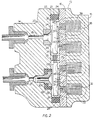
- valve body 14 constructed from a valve body 14, a solenoid block 15, and a plate 16 which is clamped between the body 14 and the block 15.
- the valve body 14 is provided with parallel bored passages 17, 18 for connection respectively, at their outer ends to the manifold 2 and to the strut 7.
- the passages 17, 18 are counterbored at 19 and 20 respectively, and both terminate in a common recess 21 of generally elliptical outline, which is disposed in the opposite end of the valve body 14 from the passages 17, 18.
- a rubber seal 22 is housed within the recess 21 to form a seal between the mating faces of the valve body 14 and the plate 16 against external leakage.
- the seal 22 includes two circular apertures 23 and 24 which define valve chambers and which are interconnected by passages 25 provided in opposite faces of a common web 26 disposed between the apertures.
- the solenoid-operated first valve 11 comprises a valve plate 27 which is disposed within the valve chamber 23 and is located resiliently by discrete angularly spaced projections 28 on the wall of the seal 22.
- the valve plate 27 is engageable with an annular rubber seating lip 29 which is retained in the counterbore 19 by means of a metal insert 30.
- the plate 27 is normally urged towards the lip 29 by means of a light spring 31, and is moved in the opposite direction to open the valve 11 by energisation of solenoid coil 32 which is housed in an annular recess 33 in the solenoid block 1 5.
- the solenoid-operated second valve 12 comprises a valve plate 34 which is disposed within the valve chamber 24 and is located resiliently by discrete angularly spaced projections 35 on the wall of the seal 22.
- the valve plate 34 is engageable with a metal seating 36 which is housed in the counterbore 20, and the seating is scratched or has an etched pattern to ensure a small leakpath past the valve 12 when the valve plate 34 is in engagement with the seating 36.
- the plate 34 is normally urged towards the seating 36 by means of a light spring 37, and is moved in the opposite direction by energisation of a solenoid coil 38 which is housed in an annular recess 39 in the solenoid block 1 5.
- the solenoid block 15 is made of ferromagnetic material.
- the plate 16 is provided with inserts 40 of non-magnetic material, preferably stainless steel.
- the inserts 40 define the magnetic poles and are brazed into openings in the plate 16 so that fluid tightness is maintained.
- the valve plates 27, 34 and the remainder of the plate 1 6 are of ferromagnetic material and complete the magnetic paths.
- the construction is such that all joints crossed by the magnetic paths can easily be ground accurately flat to preserve minimum magnetic reluctance.
- a thin film of non-magnetic material of controlled thickness is applied to the valve plate to prevent retention of residual magnetism when the coils 32, 38 are switched off.
- valve body 14, the block 15, and the plate 16 are all clamped together by bolts (not shown) and the bolts are capable of resisting any tendency for the three components to separate when the control valve is pressurised. Excessive deflection of the plate 1 6 under pressure is prevented by the stiffness of the block 15 which has substantially a greater thickness. This support allows the thickness of the plate 16 to be minimised, thereby reducing the leakage flux across the non-magnetic inserts 40.
- flux leakage can be reduced further by providing non-magnetic inserts 41 of more complex shape.
- Operation of the three-way valve 8 is such that pressure in the manifold 2, which is normally low, is cycled over a range which includes, and exceeds, the ranges of static pressure which occur in any of the struts 7.
- the frequency of the cycle is determined by the size of the orifice 10. This operation would cause negligible flow into any of the struts if all the solenoids 32, 38 of all the control valves assemblies 3, 4, 5 and 6 were de-energised, that is if all the valves 11, 12 were closed.
- Operation of the solenoid operated valves 11, 12 is controlled by an electronic control system which energises the solenoids 32, 38 to manipulate the valves in response to ride height signals.
- valve assembly 3 If the solenoid 38 of one of the valves 12 for example, that in control valve assembly 3 is energised in response to change in the dynamic loading on a strut, it opens as soon as the pressure differential across it stops acting against it. Normally this would happen within one cycle of the strut pressure "ripple" and this is supposed to be a small fraction of the pressure cycle in the manifold 2. It is therefore almost certain that the valve 12 will open before the pressure in the manifold 12 reaches the static pressure on its first cycle.
- valve 11 of the corresponding control valve When the manifold pressure exceeds the strut pressure, the valve 11 of the corresponding control valve will act as a one-way valve and fluid will flow into the strut 7 until either the pressure in the manifold 2 falls below that in the strut to cut off fluid flow through the valve 11, or the solenoid 38 of valve 12 is de-energised, thereby closing valve 12. Negligible fluid will flow into the other struts 7 because the valve 12 of the control valves 4, 5 and 6 will remain closed.
- valve 11 will open as soon as the pressure in the manifold 2 reached the pressure in the corresponding strut 7 and will be held open whilst the pressure in the manifold 2 continues its cycle.
- the valve 12 acts as a one-way valve, and fluid will flow out of the strut until the solenoid 32 of the valve 11 is de-energised thereby closing valve 11, or, which is less likely, until the strut pressure falls below that in the manifold 2 to cut off flow through the valve 12.
- each valve 12 when that valve is in the closed position is necessary to prevent the maximum pressure in a corresponding strut 7 from being trapped permanently in the valve chambers. It also reduces the pressure differential across the valve, and so reduces the magnitude of the force required to open the valve.
- the solenoids 32 and 38 are not powerful enough to open the valves 11 and 12 against any significant pressure difference. This means that the rubber lips 29 cannot be destroyed by extrusion when the valves 12 are closed, for example to provide leakproof seals to prevent a drop in strut pressure when the pressure source 1 is inoperative.
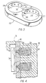
- Two control valve assemblies such as illustrated in Figure 2, can be combined into a common housing to control levelling of suspension struts of a pair of wheels on opposite sides of the vehicle.
- the solenoid block 15 can be of sintered construction provided with recesses in which four coils are received, the recesses being interconnected by slots extending into the block for the depth of the coils in order to break up the eddy currents.
- the volume of the interconnected valve chambers 23 and 24 is made expansible to ensure that the valve 11 is able to open freely.
- the seating 36 can then retract to increase the effective volume of the valve chamber 23 and 24 to compensate for the additional volume to be accommodated as the valve plate 27 moves accompanied by displacement of the rubber lip 29.
- the material of the seal may be arranged to deform in a region between the chambers 23 and 24 and the strut 7, but not between the strut 7 and atmosphere.
- Our invention therefore provides a high pressure control system in which the control 3, 4, 5 and 6 can be sealed with elastomeric elements to guarantee substantially perfect leakproofing and yet be sufficiently durable for practical use.
- our invention has the advantage that only exceptionally small forces are required to operate the control valves.
Landscapes
- Engineering & Computer Science (AREA)
- Mechanical Engineering (AREA)
- Vehicle Body Suspensions (AREA)
- Magnetically Actuated Valves (AREA)
- Fluid-Pressure Circuits (AREA)
Claims (14)
Applications Claiming Priority (2)
| Application Number | Priority Date | Filing Date | Title |
|---|---|---|---|
| GB7909297 | 1979-03-16 | ||
| GB7909297 | 1979-03-16 |
Publications (2)
| Publication Number | Publication Date |
|---|---|
| EP0017351A1 EP0017351A1 (fr) | 1980-10-15 |
| EP0017351B1 true EP0017351B1 (fr) | 1984-05-09 |
Family
ID=10503919
Family Applications (1)
| Application Number | Title | Priority Date | Filing Date |
|---|---|---|---|
| EP19800300708 Expired EP0017351B1 (fr) | 1979-03-16 | 1980-03-07 | Perfectionnements aux systèmes hydrauliques à haute pression |
Country Status (6)
| Country | Link |
|---|---|
| US (1) | US4463969A (fr) |
| EP (1) | EP0017351B1 (fr) |
| JP (1) | JPS55139506A (fr) |
| BR (1) | BR8001469A (fr) |
| DE (1) | DE3067734D1 (fr) |
| GB (1) | GB2045177B (fr) |
Families Citing this family (24)
| Publication number | Priority date | Publication date | Assignee | Title |
|---|---|---|---|---|
| GB2074956B (en) * | 1980-04-19 | 1983-11-09 | Lucas Industries Ltd | High pressure hydraulic systems |
| US4390188A (en) * | 1980-05-03 | 1983-06-28 | Lucas Industries Limited | High pressure hydraulic systems |
| DE3170528D1 (en) * | 1980-11-01 | 1985-06-20 | Lucas Ind Plc | Solenoid-operated valve means for hydraulic systems |
| FR2509390A1 (fr) * | 1981-07-09 | 1983-01-14 | Lucas Ind Plc | Perfectionnements aux systemes hydrauliques sous forte pression |
| US4541429A (en) * | 1982-05-10 | 1985-09-17 | Prosl Frank R | Implantable magnetically-actuated valve |
| JPS5952289U (ja) * | 1982-09-30 | 1984-04-06 | アイシン・エィ・ダブリュ株式会社 | 自動変速機の油圧制御装置用電磁ソレノイド弁 |
| US4541610A (en) * | 1982-11-24 | 1985-09-17 | Lucas Industries | Fluid flow control valve assemblies |
| US4588162A (en) * | 1984-06-14 | 1986-05-13 | Airmatic-Allied, Inc. | Solenoid valve |
| JPS6154310A (ja) * | 1984-08-25 | 1986-03-18 | Toyota Motor Corp | 車高調整方法 |
| JPS61197861A (ja) * | 1985-02-27 | 1986-09-02 | Diesel Kiki Co Ltd | 電磁アクチユエ−タ及びその製造方法 |
| JPS636286A (ja) * | 1986-06-25 | 1988-01-12 | Riken Seiki Kk | 制御弁 |
| JPH0735173Y2 (ja) * | 1987-09-07 | 1995-08-09 | 株式会社コガネイ | ダブルソレノイド形間接作動電磁弁 |
| US4957309A (en) * | 1988-12-29 | 1990-09-18 | Toyota Jidosha Kabushiki Kaisha | Pressure control system for suspension |
| JPH0545362U (ja) * | 1991-11-18 | 1993-06-18 | 株式会社ユニシアジエツクス | 電磁弁 |
| JPH08121633A (ja) * | 1994-10-20 | 1996-05-17 | Ranco Japan Ltd | 電磁弁 |
| JP3291161B2 (ja) * | 1995-06-12 | 2002-06-10 | 株式会社フジキン | 圧力式流量制御装置 |
| US6273224B1 (en) * | 1997-08-12 | 2001-08-14 | Hr Textron, Inc. | Shock absorber mounted electromagnetically operated damper valve |
| DE10050238A1 (de) * | 2000-10-11 | 2002-04-25 | Bosch Gmbh Robert | Magnetventilbetätigtes Steuermodul zur Fluidkontrolle bei Einspritzsystemen |
| JP2003156169A (ja) * | 2001-09-04 | 2003-05-30 | Denso Corp | 電磁式流体制御装置 |
| US7163187B2 (en) * | 2004-09-29 | 2007-01-16 | Seal Tech, Inc. | Non-sliding valve |
| CN109279679A (zh) * | 2018-10-17 | 2019-01-29 | 天津宏捷安装工程有限公司 | 紫外线消毒器防冲击保护装置 |
| CN114559783B (zh) * | 2021-03-31 | 2024-01-12 | 北京京西重工有限公司 | 用于车辆悬架的液压致动器 |
| EP4067127B1 (fr) | 2021-03-31 | 2024-06-19 | BeijingWest Industries Co. Ltd. | Actionneur de levage hydraulique de la suspension pour le réglage de la hauteur de l'assiette de l'essieu |
| US12066116B2 (en) * | 2021-06-02 | 2024-08-20 | Robertshaw Controls Company | Double flow rate gas solenoid valve |
Family Cites Families (16)
| Publication number | Priority date | Publication date | Assignee | Title |
|---|---|---|---|---|
| GB191421824A (en) * | 1914-10-31 | 1915-09-30 | Igranic Electric Co Ltd | Improved Electromagnetically-operated Valves. |
| US2366006A (en) * | 1942-08-22 | 1944-12-26 | United Aircraft Prod | Dilution valve |
| US2587356A (en) * | 1945-07-16 | 1952-02-26 | Skinner Chuck Company | Reversible valve structure |
| US2560293A (en) * | 1947-01-02 | 1951-07-10 | Dole Valve Co | Thermostatic fluid mixing valve |
| US2631612A (en) * | 1949-06-25 | 1953-03-17 | Gen Controls Co | High-pressure valve |
| US2891577A (en) * | 1956-06-18 | 1959-06-23 | Gen Motors Corp | Control device |
| US3013812A (en) * | 1956-07-11 | 1961-12-19 | Gen Motors Corp | Air flow control apparatus |
| US2929640A (en) * | 1957-05-06 | 1960-03-22 | Gen Motors Corp | Height adjuster for automobile suspension |
| GB882493A (en) * | 1959-01-20 | 1961-11-15 | Saturn Ind Gases Ltd | Gas control valve |
| US3140727A (en) * | 1961-12-26 | 1964-07-14 | Gen Electric | Pilot controlled valve |
| US3399697A (en) * | 1965-07-06 | 1968-09-03 | Dole Valve Co | Solenoid valve |
| US3537355A (en) * | 1966-12-14 | 1970-11-03 | George N Bliss | Fluid-operated servomechanism |
| US3866895A (en) * | 1973-10-01 | 1975-02-18 | Midland Ross Corp | Suspension system for vehicles |
| US4044794A (en) * | 1975-11-10 | 1977-08-30 | Johnson Controls, Inc. | Slow-opening gas valve |
| US4150684A (en) * | 1977-01-25 | 1979-04-24 | Kervin Willis D | Mixing valve and control system therefor |
| JPS5475719A (en) * | 1977-11-25 | 1979-06-16 | Nissan Motor Co Ltd | Hidro-pneumatic suspension |
-
1980
- 1980-03-07 EP EP19800300708 patent/EP0017351B1/fr not_active Expired
- 1980-03-07 DE DE8080300708T patent/DE3067734D1/de not_active Expired
- 1980-03-07 GB GB8007869A patent/GB2045177B/en not_active Expired
- 1980-03-12 BR BR8001469A patent/BR8001469A/pt unknown
- 1980-03-14 JP JP3258980A patent/JPS55139506A/ja active Pending
-
1982
- 1982-11-15 US US06/441,776 patent/US4463969A/en not_active Expired - Fee Related
Also Published As
| Publication number | Publication date |
|---|---|
| EP0017351A1 (fr) | 1980-10-15 |
| US4463969A (en) | 1984-08-07 |
| DE3067734D1 (en) | 1984-06-14 |
| GB2045177A (en) | 1980-10-29 |
| JPS55139506A (en) | 1980-10-31 |
| GB2045177B (en) | 1982-10-20 |
| BR8001469A (pt) | 1980-11-11 |
Similar Documents
| Publication | Publication Date | Title |
|---|---|---|
| US4463969A (en) | High pressure hydraulic systems | |
| EP0039573B1 (fr) | Systèmes hydrauliques à haute pression | |
| US5069420A (en) | Proportional pressure control valve | |
| US5067687A (en) | Proportional pressure control valve | |
| EP0526471B1 (fr) | Vanne de commande de fluide | |
| EP0795088B1 (fr) | Vanne equilibree en pression | |
| US6283259B1 (en) | Hydraulic shock absorber | |
| US5180039A (en) | Fluid passage unit | |
| US5035306A (en) | Adjustable damping force hydraulic shock absorber | |
| EP2150723B1 (fr) | Amortisseurs magnéto-rhéologiques pour systèmes de suspension semi-actifs | |
| US5178359A (en) | Porportional pressure control valve | |
| US4988967A (en) | Solenoid operated hydraulic control valve | |
| US20030067103A1 (en) | Dual rate air spring | |
| US4508012A (en) | High pressure hydraulic systems | |
| US4951916A (en) | Pressure-balanced electromagnetic valve | |
| EP0038638B1 (fr) | Systèmes hydrauliques à haute pression | |
| CA1185875A (fr) | Valve multiple utilisee avec les appareils de dialyse | |
| US3223104A (en) | Electro-hydraulic servo valve | |
| GB2338050A (en) | Pressure balanced solenoid valve | |
| JPH11218253A (ja) | 比例電磁式方向絞り弁 | |
| JP4041924B2 (ja) | 減衰力調整式油圧緩衝器 | |
| US3753546A (en) | Sleeve valve | |
| US3900046A (en) | Control valve for accumulator systems, especially for servo brakes of motor vehicles | |
| US20250243946A1 (en) | Systems and Methods for Valve Actuation | |
| CA2182462C (fr) | Robinet de freinage de vehicule ferroviaire |
Legal Events
| Date | Code | Title | Description |
|---|---|---|---|
| PUAI | Public reference made under article 153(3) epc to a published international application that has entered the european phase |
Free format text: ORIGINAL CODE: 0009012 |
|
| AK | Designated contracting states |
Designated state(s): DE FR IT NL |
|
| 17P | Request for examination filed |
Effective date: 19810316 |
|
| RAP1 | Party data changed (applicant data changed or rights of an application transferred) |
Owner name: LUCAS INDUSTRIES PLC |
|
| ITF | It: translation for a ep patent filed | ||
| RBV | Designated contracting states (corrected) |
Designated state(s): DE FR IT NL |
|
| ITF | It: translation for a ep patent filed | ||
| GRAA | (expected) grant |
Free format text: ORIGINAL CODE: 0009210 |
|
| AK | Designated contracting states |
Designated state(s): DE FR IT NL |
|
| REF | Corresponds to: |
Ref document number: 3067734 Country of ref document: DE Date of ref document: 19840614 |
|
| ET | Fr: translation filed | ||
| PLBE | No opposition filed within time limit |
Free format text: ORIGINAL CODE: 0009261 |
|
| STAA | Information on the status of an ep patent application or granted ep patent |
Free format text: STATUS: NO OPPOSITION FILED WITHIN TIME LIMIT |
|
| 26N | No opposition filed | ||
| PGFP | Annual fee paid to national office [announced via postgrant information from national office to epo] |
Ref country code: DE Payment date: 19900223 Year of fee payment: 11 |
|
| PGFP | Annual fee paid to national office [announced via postgrant information from national office to epo] |
Ref country code: NL Payment date: 19900331 Year of fee payment: 11 |
|
| PGFP | Annual fee paid to national office [announced via postgrant information from national office to epo] |
Ref country code: FR Payment date: 19910222 Year of fee payment: 12 |
|
| ITTA | It: last paid annual fee | ||
| PG25 | Lapsed in a contracting state [announced via postgrant information from national office to epo] |
Ref country code: NL Effective date: 19911001 |
|
| NLV4 | Nl: lapsed or anulled due to non-payment of the annual fee | ||
| PG25 | Lapsed in a contracting state [announced via postgrant information from national office to epo] |
Ref country code: DE Effective date: 19920101 |
|
| PG25 | Lapsed in a contracting state [announced via postgrant information from national office to epo] |
Ref country code: FR Effective date: 19921130 |
|
| REG | Reference to a national code |
Ref country code: FR Ref legal event code: ST |