EP0017509A1 - Träger für Ausrüstung - Google Patents
Träger für Ausrüstung Download PDFInfo
- Publication number
- EP0017509A1 EP0017509A1 EP80301117A EP80301117A EP0017509A1 EP 0017509 A1 EP0017509 A1 EP 0017509A1 EP 80301117 A EP80301117 A EP 80301117A EP 80301117 A EP80301117 A EP 80301117A EP 0017509 A1 EP0017509 A1 EP 0017509A1
- Authority
- EP
- European Patent Office
- Prior art keywords
- fitment
- root
- end portion
- slot
- combination
- Prior art date
- Legal status (The legal status is an assumption and is not a legal conclusion. Google has not performed a legal analysis and makes no representation as to the accuracy of the status listed.)
- Withdrawn
Links
Images

Classifications
-
- F—MECHANICAL ENGINEERING; LIGHTING; HEATING; WEAPONS; BLASTING
- F16—ENGINEERING ELEMENTS AND UNITS; GENERAL MEASURES FOR PRODUCING AND MAINTAINING EFFECTIVE FUNCTIONING OF MACHINES OR INSTALLATIONS; THERMAL INSULATION IN GENERAL
- F16B—DEVICES FOR FASTENING OR SECURING CONSTRUCTIONAL ELEMENTS OR MACHINE PARTS TOGETHER, e.g. NAILS, BOLTS, CIRCLIPS, CLAMPS, CLIPS OR WEDGES; JOINTS OR JOINTING
- F16B5/00—Joining sheets or plates, e.g. panels, to one another or to strips or bars parallel to them
-
- E—FIXED CONSTRUCTIONS
- E01—CONSTRUCTION OF ROADS, RAILWAYS, OR BRIDGES
- E01F—ADDITIONAL WORK, SUCH AS EQUIPPING ROADS OR THE CONSTRUCTION OF PLATFORMS, HELICOPTER LANDING STAGES, SIGNS, SNOW FENCES, OR THE LIKE
- E01F9/00—Arrangement of road signs or traffic signals; Arrangements for enforcing caution
- E01F9/60—Upright bodies, e.g. marker posts or bollards; Supports for road signs
- E01F9/623—Upright bodies, e.g. marker posts or bollards; Supports for road signs characterised by form or by structural features, e.g. for enabling displacement or deflection
- E01F9/65—Upright bodies, e.g. marker posts or bollards; Supports for road signs characterised by form or by structural features, e.g. for enabling displacement or deflection with rotatable, swingable or adjustable signs or signals
-
- E—FIXED CONSTRUCTIONS
- E04—BUILDING
- E04B—GENERAL BUILDING CONSTRUCTIONS; WALLS, e.g. PARTITIONS; ROOFS; FLOORS; CEILINGS; INSULATION OR OTHER PROTECTION OF BUILDINGS
- E04B2/00—Walls, e.g. partitions, for buildings; Wall construction with regard to insulation; Connections specially adapted to walls
- E04B2/74—Removable non-load-bearing partitions; Partitions with a free upper edge
- E04B2/7407—Removable non-load-bearing partitions; Partitions with a free upper edge assembled using frames with infill panels or coverings only; made-up of panels and a support structure incorporating posts
- E04B2/7416—Removable non-load-bearing partitions; Partitions with a free upper edge assembled using frames with infill panels or coverings only; made-up of panels and a support structure incorporating posts with free upper edge, e.g. for use as office space dividers
- E04B2/7433—Removable non-load-bearing partitions; Partitions with a free upper edge assembled using frames with infill panels or coverings only; made-up of panels and a support structure incorporating posts with free upper edge, e.g. for use as office space dividers with panels and support posts
- E04B2/7438—Removable non-load-bearing partitions; Partitions with a free upper edge assembled using frames with infill panels or coverings only; made-up of panels and a support structure incorporating posts with free upper edge, e.g. for use as office space dividers with panels and support posts with adjustable angular connection of panels to posts
- E04B2/7442—Removable non-load-bearing partitions; Partitions with a free upper edge assembled using frames with infill panels or coverings only; made-up of panels and a support structure incorporating posts with free upper edge, e.g. for use as office space dividers with panels and support posts with adjustable angular connection of panels to posts hinged connections
-
- G—PHYSICS
- G09—EDUCATION; CRYPTOGRAPHY; DISPLAY; ADVERTISING; SEALS
- G09F—DISPLAYING; ADVERTISING; SIGNS; LABELS OR NAME-PLATES; SEALS
- G09F15/00—Boards, hoardings, pillars, or like structures for notices, placards, posters, or the like
- G09F15/0068—Modular articulated structures, e.g. stands, and articulation means therefor
-
- G—PHYSICS
- G09—EDUCATION; CRYPTOGRAPHY; DISPLAY; ADVERTISING; SEALS
- G09F—DISPLAYING; ADVERTISING; SIGNS; LABELS OR NAME-PLATES; SEALS
- G09F7/00—Signs, name or number plates, letters, numerals, or symbols; Panels or boards
- G09F7/18—Means for attaching signs, plates, panels, or boards to a supporting structure
- G09F7/20—Means for attaching signs, plates, panels, or boards to a supporting structure for adjustably mounting
Definitions
- the present invention is concerned with the support of fitments generally. More particularly, but by no means exclusively, the invention is concerned with display systems of the kind in which fitments such as panels are supported from uprights.
- the present invention seeks, inter alia, to provide a display system which is relatively simple in construction and is readily adjustable to meet the needs of the user.
- a fitment and a support therefor comprising an elongate member provided with at least one elongate slot or groove extending therealong and configured for sliding receipt of a root -end portion of the fitment inserted therein, the root -end portion of the fitment being shaped to allow pivotal movement of the fitment about the axis of the slot or groove while located therein, and the root-end portion of the fitment being provided with locking means adapted for co-operation with the slot or groove for securing the fitment to the support in a position which may be selected both longitudinally and pivotally.
- the support need not comprise a vertical post. It may for example extend horizontally, or indeed at any angle between horizontal and vertical depending upon the particular requirements.
- the fitment may comprise virtually anything which it is desired to support. Examples which spring to mind include lighting fitments, receptacles, brackets, shelving, and panels. No doubt other fitments which could usefully be supported in the manner of the present invention will readily occur to the reader.
- the elongate member may conveniently be formed as an extrusion of aluminium or its alloys or of plastics.
- the slot or groove may conveniently be formed as a part cylindrical surface, and in that case the root-end portion of the fitment may suitably be formed as a cylinder with an integral web or flange to which, for example, a display panel may be coupled by threaded connectors.
- the pivotal movement of the fitment relative to the support will then be of the nature of a hinge.
- the locking means suitably comprise means mounted on the root-end portion and which can be expanded by application of a tool to wedge the root-end portion in the slot.
- the locking means comprise a threaded member with a head dimensioned for reception of an Allen Key.
- the root-end portion may comprise a ball so that the pivoting of the root-end portion in the slot is in the manner of a socket joint.
- a display system comprising one or more fitments supported from uprights, each upright comprising an extruded section defining one or more elongate slots or grooves, and the one or more fitments having root-end portions received in said slots or grooves so as to be longitudinally slidable therein, so as to be moveable therein in the manner of a hinge or of a socket joint, and being selectively lockable therein.
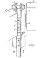
- the display system shown in Figs. 1 and 2 comprises one or more uprights 1 (only one is shown in the drawing) consisting of an extruded hollow section, suitably formed of aluminium, one of its alloys, or of plastics. Tow panels 2 are supported from the upright, and the position and orientation of the panels may be varied, as will be explained.
- the upright defines four elongate slots or grooves 3 running therealong. Modified arrangements including a greater o-r lesser number of slots or grooves 3 could readily be.designed.
- the groove 3 illustrated comprises a part cylindrical surface; and the panels 2 are provided with root-end portions 4 which consist of a cylindrical hinge member 5 from which extends a web 6 terminating in a flange 7 at right angles thereto.
- Alternative, but plainly less preferable, arrangements could be devised in which the slot surface does not consist of a part cylindrical surface and the hinge member 5 is not cylindrical. It is essential, however, that the root-end portion be shaped to allow pivotal movement of the fitment about the axis of the slot or groove 3.
- the cylindrical hinge member 5 may be inserted into the groove either at its extreme longitudinal end or at an intermediate portion cut away as indicated by dotted lines in Fig. 1 at 8.
- the hinge member 5 is not a tight fit in the groove. It may be slid axially thereof to position the panel 2 longitudinally and it allows pivotal movement about the axis of the slot or groove 3 to vary the orientation of the panels relative to each other and to the upright.
- Locking means 9 are provided in the root-end portions of the fitments and suitably comprise threaded members extending, for example, along the lines indicated at 10 in Fig. 1 and adapted to be extended into the slot by turning a headed portion 11 of the locking means, as for example by an Allen Key, so as to wedge the hinge member 5 in the slot.
- One or more feet 12 may be provided at the bottom of the upright for supporting the same and these may be mounted in the slots 3 in an exactly similar fashion.
- the panels 2 of the embodiment of Figs. 1 and 2 can readily be adjusted in position both vertically and pivotally by loosening the locking means, adjusting the panel by hand and re-locking.
Landscapes
- Engineering & Computer Science (AREA)
- Physics & Mathematics (AREA)
- General Physics & Mathematics (AREA)
- Theoretical Computer Science (AREA)
- Architecture (AREA)
- Civil Engineering (AREA)
- Structural Engineering (AREA)
- General Engineering & Computer Science (AREA)
- Electromagnetism (AREA)
- Mechanical Engineering (AREA)
- Illuminated Signs And Luminous Advertising (AREA)
- Mirrors, Picture Frames, Photograph Stands, And Related Fastening Devices (AREA)
Applications Claiming Priority (2)
| Application Number | Priority Date | Filing Date | Title |
|---|---|---|---|
| GB7912028 | 1979-04-05 | ||
| GB7912028A GB2045856A (en) | 1979-04-05 | 1979-04-05 | Supporting fitments |
Publications (1)
| Publication Number | Publication Date |
|---|---|
| EP0017509A1 true EP0017509A1 (de) | 1980-10-15 |
Family
ID=10504359
Family Applications (1)
| Application Number | Title | Priority Date | Filing Date |
|---|---|---|---|
| EP80301117A Withdrawn EP0017509A1 (de) | 1979-04-05 | 1980-04-08 | Träger für Ausrüstung |
Country Status (2)
| Country | Link |
|---|---|
| EP (1) | EP0017509A1 (de) |
| GB (1) | GB2045856A (de) |
Cited By (10)
| Publication number | Priority date | Publication date | Assignee | Title |
|---|---|---|---|---|
| GB2137795A (en) * | 1983-04-06 | 1984-10-10 | Michael Peter Gifford Hull | Sign posts |
| FR2576048A1 (fr) * | 1985-01-15 | 1986-07-18 | Neyton Jean Claude | Mat de support pour mobiliers urbains, ainsi que les mobiliers urbains obtenus a l'aide de ce mat |
| FR2580108A1 (en) * | 1985-04-05 | 1986-10-10 | Gosset Philippe | Module for light display panels |
| EP0223338A1 (de) * | 1985-09-19 | 1987-05-27 | OLIVETTI SYNTHESIS S.p.A. | Einrichtung zum Verbinden von Platten |
| EP0274984A1 (de) * | 1986-12-10 | 1988-07-20 | Entwurf Partner Ruedi Zwissler | Vorrichtung zum austauschbaren Befestigen von Schildern und dergleichen |
| DE4004918A1 (de) * | 1990-02-17 | 1991-08-22 | Display & Design Helmut Amelun | Tafelfoermiger werbetraeger |
| AT1692U1 (de) * | 1996-04-23 | 1997-09-25 | Hrovat Thomas | Stützgestell zum abstützen hochgestellter schautafeln od.dgl. |
| WO2002048474A1 (en) * | 2000-12-11 | 2002-06-20 | N.V. Kema | Wall system |
| ITPD20100101A1 (it) * | 2010-03-31 | 2011-10-01 | Fernova Srl | Parete divisoria |
| CN105124935A (zh) * | 2015-09-30 | 2015-12-09 | 宋莉芳 | 一种拼接式规格化的搁物架组件 |
Families Citing this family (5)
| Publication number | Priority date | Publication date | Assignee | Title |
|---|---|---|---|---|
| GB2159573B (en) * | 1984-05-30 | 1987-09-16 | Venesta International Componen | Improvements in and relating to hinges and door stop assemblies |
| GB2214961A (en) * | 1988-02-20 | 1989-09-13 | Duraflex Ltd | Roof; bay window |
| DE4317307A1 (de) * | 1993-05-25 | 1994-12-01 | Hans Joachim Muehl | Verfahren zum Verbinden von zwei Werkteilen |
| DE20207435U1 (de) * | 2002-05-11 | 2003-09-25 | Transnorm System GmbH, 31177 Harsum | Profilelement, insbesondere für Seitenwangen eines Fördersystems |
| DE10304041A1 (de) * | 2003-02-01 | 2004-08-05 | Kolbus Gmbh & Co. Kg | Profilkörper für Rahmenkonstruktionen und Verwendung des Profilkörpers in einer Verkleidung |
Citations (6)
| Publication number | Priority date | Publication date | Assignee | Title |
|---|---|---|---|---|
| BE634122A (de) * | ||||
| CH454407A (fr) * | 1965-10-12 | 1968-04-15 | Lambert Paul | Cloison démontable |
| US3419064A (en) * | 1966-12-12 | 1968-12-31 | Oddicini Renzo | Articulated structure particularly for partitions |
| DE1561580A1 (de) * | 1967-09-07 | 1970-04-02 | Werner Klee | Vorrichtung zur Schaustellung von Plaenen,Zeichnungen u.dgl. |
| DE1933378A1 (de) * | 1968-10-08 | 1970-04-16 | Klem Verbindungselemente Theo | Fa. Verbindungselement zur Verbindung von Platten |
| GB1316431A (en) * | 1969-06-17 | 1973-05-09 | Nova Consultant Designers Ltd | Display system screens and the like |
-
1979
- 1979-04-05 GB GB7912028A patent/GB2045856A/en not_active Withdrawn
-
1980
- 1980-04-08 EP EP80301117A patent/EP0017509A1/de not_active Withdrawn
Patent Citations (6)
| Publication number | Priority date | Publication date | Assignee | Title |
|---|---|---|---|---|
| BE634122A (de) * | ||||
| CH454407A (fr) * | 1965-10-12 | 1968-04-15 | Lambert Paul | Cloison démontable |
| US3419064A (en) * | 1966-12-12 | 1968-12-31 | Oddicini Renzo | Articulated structure particularly for partitions |
| DE1561580A1 (de) * | 1967-09-07 | 1970-04-02 | Werner Klee | Vorrichtung zur Schaustellung von Plaenen,Zeichnungen u.dgl. |
| DE1933378A1 (de) * | 1968-10-08 | 1970-04-16 | Klem Verbindungselemente Theo | Fa. Verbindungselement zur Verbindung von Platten |
| GB1316431A (en) * | 1969-06-17 | 1973-05-09 | Nova Consultant Designers Ltd | Display system screens and the like |
Cited By (10)
| Publication number | Priority date | Publication date | Assignee | Title |
|---|---|---|---|---|
| GB2137795A (en) * | 1983-04-06 | 1984-10-10 | Michael Peter Gifford Hull | Sign posts |
| FR2576048A1 (fr) * | 1985-01-15 | 1986-07-18 | Neyton Jean Claude | Mat de support pour mobiliers urbains, ainsi que les mobiliers urbains obtenus a l'aide de ce mat |
| FR2580108A1 (en) * | 1985-04-05 | 1986-10-10 | Gosset Philippe | Module for light display panels |
| EP0223338A1 (de) * | 1985-09-19 | 1987-05-27 | OLIVETTI SYNTHESIS S.p.A. | Einrichtung zum Verbinden von Platten |
| EP0274984A1 (de) * | 1986-12-10 | 1988-07-20 | Entwurf Partner Ruedi Zwissler | Vorrichtung zum austauschbaren Befestigen von Schildern und dergleichen |
| DE4004918A1 (de) * | 1990-02-17 | 1991-08-22 | Display & Design Helmut Amelun | Tafelfoermiger werbetraeger |
| AT1692U1 (de) * | 1996-04-23 | 1997-09-25 | Hrovat Thomas | Stützgestell zum abstützen hochgestellter schautafeln od.dgl. |
| WO2002048474A1 (en) * | 2000-12-11 | 2002-06-20 | N.V. Kema | Wall system |
| ITPD20100101A1 (it) * | 2010-03-31 | 2011-10-01 | Fernova Srl | Parete divisoria |
| CN105124935A (zh) * | 2015-09-30 | 2015-12-09 | 宋莉芳 | 一种拼接式规格化的搁物架组件 |
Also Published As
| Publication number | Publication date |
|---|---|
| GB2045856A (en) | 1980-11-05 |
Similar Documents
| Publication | Publication Date | Title |
|---|---|---|
| GB2045856A (en) | Supporting fitments | |
| CA2199315C (en) | Work surface support arrangement for office panelling systems | |
| US4493172A (en) | Connector system | |
| US5415472A (en) | Portable shelf | |
| US5816568A (en) | Component holding system | |
| US5292189A (en) | Sub-panel guide system for electrical enclosure | |
| US5174532A (en) | Leg assembly | |
| US7096637B2 (en) | Display structure and system | |
| US5067294A (en) | Partition assembly | |
| US4875418A (en) | Set of components for constructing furniture pieces | |
| EP0707807A2 (de) | Büromöbel | |
| US5689926A (en) | Modular panel system | |
| EP1011382A1 (de) | Ein möbelsystem bestehend aus arbeitsplatten, die mit beschlägen ausgerüstet werden können | |
| US4953338A (en) | Screen assembly | |
| US20040118061A1 (en) | Universal stud for demountable wall partitions and demountable ceiling panels | |
| US6363663B1 (en) | Post engaging brackets for partitions | |
| US20010017009A1 (en) | Office furniture system | |
| US4260124A (en) | Easel | |
| US4351017A (en) | Ambient light | |
| EP2166170A1 (de) | Modulares Möbelsystem | |
| CA1298703C (en) | Screen assembly | |
| US4503981A (en) | Drafting tool support apparatus | |
| US5464295A (en) | Articulated frame element for modular furniture, and hinge for articulating two frame elements together | |
| US4335861A (en) | Shelving system | |
| JPS58176998A (ja) | 車載用支持台 |
Legal Events
| Date | Code | Title | Description |
|---|---|---|---|
| PUAI | Public reference made under article 153(3) epc to a published international application that has entered the european phase |
Free format text: ORIGINAL CODE: 0009012 |
|
| AK | Designated contracting states |
Designated state(s): AT BE CH DE FR IT NL SE |
|
| 17P | Request for examination filed |
Effective date: 19810414 |
|
| STAA | Information on the status of an ep patent application or granted ep patent |
Free format text: STATUS: THE APPLICATION HAS BEEN WITHDRAWN |
|
| 18W | Application withdrawn |
Withdrawal date: 19820618 |
|
| RIN1 | Information on inventor provided before grant (corrected) |
Inventor name: WOODCOCK, KEITH GEORGE |