EP0017519A2 - Trockenstaubsauger für Bodenflächen - Google Patents
Trockenstaubsauger für Bodenflächen Download PDFInfo
- Publication number
- EP0017519A2 EP0017519A2 EP80400297A EP80400297A EP0017519A2 EP 0017519 A2 EP0017519 A2 EP 0017519A2 EP 80400297 A EP80400297 A EP 80400297A EP 80400297 A EP80400297 A EP 80400297A EP 0017519 A2 EP0017519 A2 EP 0017519A2
- Authority
- EP
- European Patent Office
- Prior art keywords
- tank
- suction
- machine
- enclosure
- machine according
- Prior art date
- Legal status (The legal status is an assumption and is not a legal conclusion. Google has not performed a legal analysis and makes no representation as to the accuracy of the status listed.)
- Granted
Links
- 238000010407 vacuum cleaning Methods 0.000 title 1
- 239000007788 liquid Substances 0.000 claims abstract description 47
- 238000004140 cleaning Methods 0.000 claims abstract description 22
- XLYOFNOQVPJJNP-UHFFFAOYSA-N water Substances O XLYOFNOQVPJJNP-UHFFFAOYSA-N 0.000 claims description 39
- 239000000428 dust Substances 0.000 claims description 24
- 239000003599 detergent Substances 0.000 claims description 23
- 230000009471 action Effects 0.000 claims description 20
- 238000010438 heat treatment Methods 0.000 claims description 12
- 238000005507 spraying Methods 0.000 claims description 11
- 238000005096 rolling process Methods 0.000 claims description 8
- 239000012530 fluid Substances 0.000 claims description 7
- 230000000694 effects Effects 0.000 claims description 5
- 230000002093 peripheral effect Effects 0.000 claims description 3
- 150000003839 salts Chemical class 0.000 claims description 3
- 241000270295 Serpentes Species 0.000 claims 1
- 150000001768 cations Chemical class 0.000 claims 1
- 238000013461 design Methods 0.000 abstract description 4
- 239000002245 particle Substances 0.000 abstract description 2
- 238000000605 extraction Methods 0.000 description 13
- 239000007921 spray Substances 0.000 description 10
- 239000012535 impurity Substances 0.000 description 9
- 239000000463 material Substances 0.000 description 6
- 210000000056 organ Anatomy 0.000 description 5
- 239000002689 soil Substances 0.000 description 5
- 230000008901 benefit Effects 0.000 description 4
- 230000008878 coupling Effects 0.000 description 4
- 238000010168 coupling process Methods 0.000 description 4
- 238000005859 coupling reaction Methods 0.000 description 4
- 239000000835 fiber Substances 0.000 description 4
- 230000036961 partial effect Effects 0.000 description 3
- 239000008237 rinsing water Substances 0.000 description 3
- 229920002994 synthetic fiber Polymers 0.000 description 3
- 238000011144 upstream manufacturing Methods 0.000 description 3
- 239000002351 wastewater Substances 0.000 description 3
- 238000000151 deposition Methods 0.000 description 2
- 238000007599 discharging Methods 0.000 description 2
- 238000009429 electrical wiring Methods 0.000 description 2
- 238000003466 welding Methods 0.000 description 2
- 229920002160 Celluloid Polymers 0.000 description 1
- RYGMFSIKBFXOCR-UHFFFAOYSA-N Copper Chemical compound [Cu] RYGMFSIKBFXOCR-UHFFFAOYSA-N 0.000 description 1
- 241000264877 Hippospongia communis Species 0.000 description 1
- 241001465754 Metazoa Species 0.000 description 1
- 238000004026 adhesive bonding Methods 0.000 description 1
- 239000011324 bead Substances 0.000 description 1
- 230000000903 blocking effect Effects 0.000 description 1
- 230000015556 catabolic process Effects 0.000 description 1
- 238000004891 communication Methods 0.000 description 1
- 239000004020 conductor Substances 0.000 description 1
- 230000001276 controlling effect Effects 0.000 description 1
- 229910052802 copper Inorganic materials 0.000 description 1
- 239000010949 copper Substances 0.000 description 1
- 239000007799 cork Substances 0.000 description 1
- 238000010908 decantation Methods 0.000 description 1
- 230000003247 decreasing effect Effects 0.000 description 1
- 230000008021 deposition Effects 0.000 description 1
- 239000000645 desinfectant Substances 0.000 description 1
- 238000007865 diluting Methods 0.000 description 1
- 238000005108 dry cleaning Methods 0.000 description 1
- 238000001035 drying Methods 0.000 description 1
- 239000000284 extract Substances 0.000 description 1
- 230000005484 gravity Effects 0.000 description 1
- 239000011810 insulating material Substances 0.000 description 1
- 230000009916 joint effect Effects 0.000 description 1
- 238000012423 maintenance Methods 0.000 description 1
- 238000000034 method Methods 0.000 description 1
- 238000012544 monitoring process Methods 0.000 description 1
- 238000000465 moulding Methods 0.000 description 1
- 230000000149 penetrating effect Effects 0.000 description 1
- 239000011148 porous material Substances 0.000 description 1
- 238000003825 pressing Methods 0.000 description 1
- 230000008569 process Effects 0.000 description 1
- 230000001681 protective effect Effects 0.000 description 1
- 230000002829 reductive effect Effects 0.000 description 1
- 230000001105 regulatory effect Effects 0.000 description 1
- 230000008439 repair process Effects 0.000 description 1
- 230000000717 retained effect Effects 0.000 description 1
- 230000002441 reversible effect Effects 0.000 description 1
- 239000000725 suspension Substances 0.000 description 1
- 239000012209 synthetic fiber Substances 0.000 description 1
- 238000005496 tempering Methods 0.000 description 1
- 239000004753 textile Substances 0.000 description 1
- 210000002268 wool Anatomy 0.000 description 1
Images





Classifications
-
- A—HUMAN NECESSITIES
- A47—FURNITURE; DOMESTIC ARTICLES OR APPLIANCES; COFFEE MILLS; SPICE MILLS; SUCTION CLEANERS IN GENERAL
- A47L—DOMESTIC WASHING OR CLEANING; SUCTION CLEANERS IN GENERAL
- A47L9/00—Details or accessories of suction cleaners, e.g. mechanical means for controlling the suction or for effecting pulsating action; Storing devices specially adapted to suction cleaners or parts thereof; Carrying-vehicles specially adapted for suction cleaners
- A47L9/10—Filters; Dust separators; Dust removal; Automatic exchange of filters
- A47L9/16—Arrangement or disposition of cyclones or other devices with centrifugal action
- A47L9/165—Construction of inlets
-
- A—HUMAN NECESSITIES
- A47—FURNITURE; DOMESTIC ARTICLES OR APPLIANCES; COFFEE MILLS; SPICE MILLS; SUCTION CLEANERS IN GENERAL
- A47L—DOMESTIC WASHING OR CLEANING; SUCTION CLEANERS IN GENERAL
- A47L11/00—Machines for cleaning floors, carpets, furniture, walls, or wall coverings
- A47L11/02—Floor surfacing or polishing machines
- A47L11/10—Floor surfacing or polishing machines motor-driven
- A47L11/14—Floor surfacing or polishing machines motor-driven with rotating tools
-
- A—HUMAN NECESSITIES
- A47—FURNITURE; DOMESTIC ARTICLES OR APPLIANCES; COFFEE MILLS; SPICE MILLS; SUCTION CLEANERS IN GENERAL
- A47L—DOMESTIC WASHING OR CLEANING; SUCTION CLEANERS IN GENERAL
- A47L11/00—Machines for cleaning floors, carpets, furniture, walls, or wall coverings
- A47L11/34—Machines for treating carpets in position by liquid, foam, or vapour, e.g. by steam
-
- A—HUMAN NECESSITIES
- A47—FURNITURE; DOMESTIC ARTICLES OR APPLIANCES; COFFEE MILLS; SPICE MILLS; SUCTION CLEANERS IN GENERAL
- A47L—DOMESTIC WASHING OR CLEANING; SUCTION CLEANERS IN GENERAL
- A47L11/00—Machines for cleaning floors, carpets, furniture, walls, or wall coverings
- A47L11/40—Parts or details of machines not provided for in groups A47L11/02 - A47L11/38, or not restricted to one of these groups, e.g. handles, arrangements of switches, skirts, buffers, levers
- A47L11/4036—Parts or details of the surface treating tools
- A47L11/4041—Roll shaped surface treating tools
-
- A—HUMAN NECESSITIES
- A47—FURNITURE; DOMESTIC ARTICLES OR APPLIANCES; COFFEE MILLS; SPICE MILLS; SUCTION CLEANERS IN GENERAL
- A47L—DOMESTIC WASHING OR CLEANING; SUCTION CLEANERS IN GENERAL
- A47L11/00—Machines for cleaning floors, carpets, furniture, walls, or wall coverings
- A47L11/40—Parts or details of machines not provided for in groups A47L11/02 - A47L11/38, or not restricted to one of these groups, e.g. handles, arrangements of switches, skirts, buffers, levers
- A47L11/4036—Parts or details of the surface treating tools
- A47L11/4044—Vacuuming or pick-up tools; Squeegees
-
- A—HUMAN NECESSITIES
- A47—FURNITURE; DOMESTIC ARTICLES OR APPLIANCES; COFFEE MILLS; SPICE MILLS; SUCTION CLEANERS IN GENERAL
- A47L—DOMESTIC WASHING OR CLEANING; SUCTION CLEANERS IN GENERAL
- A47L11/00—Machines for cleaning floors, carpets, furniture, walls, or wall coverings
- A47L11/40—Parts or details of machines not provided for in groups A47L11/02 - A47L11/38, or not restricted to one of these groups, e.g. handles, arrangements of switches, skirts, buffers, levers
- A47L11/408—Means for supplying cleaning or surface treating agents
- A47L11/4088—Supply pumps; Spraying devices; Supply conduits
-
- A—HUMAN NECESSITIES
- A47—FURNITURE; DOMESTIC ARTICLES OR APPLIANCES; COFFEE MILLS; SPICE MILLS; SUCTION CLEANERS IN GENERAL
- A47L—DOMESTIC WASHING OR CLEANING; SUCTION CLEANERS IN GENERAL
- A47L7/00—Suction cleaners adapted for additional purposes; Tables with suction openings for cleaning purposes; Containers for cleaning articles by suction; Suction cleaners adapted to cleaning of brushes; Suction cleaners adapted to taking-up liquids
- A47L7/0004—Suction cleaners adapted to take up liquids, e.g. wet or dry vacuum cleaners
- A47L7/0009—Suction cleaners adapted to take up liquids, e.g. wet or dry vacuum cleaners with means mounted on the nozzle; nozzles specially adapted for the recovery of liquid
-
- A—HUMAN NECESSITIES
- A47—FURNITURE; DOMESTIC ARTICLES OR APPLIANCES; COFFEE MILLS; SPICE MILLS; SUCTION CLEANERS IN GENERAL
- A47L—DOMESTIC WASHING OR CLEANING; SUCTION CLEANERS IN GENERAL
- A47L7/00—Suction cleaners adapted for additional purposes; Tables with suction openings for cleaning purposes; Containers for cleaning articles by suction; Suction cleaners adapted to cleaning of brushes; Suction cleaners adapted to taking-up liquids
- A47L7/0004—Suction cleaners adapted to take up liquids, e.g. wet or dry vacuum cleaners
- A47L7/0023—Recovery tanks
- A47L7/0028—Security means, e.g. float valves or level switches for preventing overflow
-
- A—HUMAN NECESSITIES
- A47—FURNITURE; DOMESTIC ARTICLES OR APPLIANCES; COFFEE MILLS; SPICE MILLS; SUCTION CLEANERS IN GENERAL
- A47L—DOMESTIC WASHING OR CLEANING; SUCTION CLEANERS IN GENERAL
- A47L7/00—Suction cleaners adapted for additional purposes; Tables with suction openings for cleaning purposes; Containers for cleaning articles by suction; Suction cleaners adapted to cleaning of brushes; Suction cleaners adapted to taking-up liquids
- A47L7/0004—Suction cleaners adapted to take up liquids, e.g. wet or dry vacuum cleaners
- A47L7/0042—Gaskets; Sealing means
-
- A—HUMAN NECESSITIES
- A47—FURNITURE; DOMESTIC ARTICLES OR APPLIANCES; COFFEE MILLS; SPICE MILLS; SUCTION CLEANERS IN GENERAL
- A47L—DOMESTIC WASHING OR CLEANING; SUCTION CLEANERS IN GENERAL
- A47L9/00—Details or accessories of suction cleaners, e.g. mechanical means for controlling the suction or for effecting pulsating action; Storing devices specially adapted to suction cleaners or parts thereof; Carrying-vehicles specially adapted for suction cleaners
- A47L9/10—Filters; Dust separators; Dust removal; Automatic exchange of filters
- A47L9/14—Bags or the like; Rigid filtering receptacles; Attachment of, or closures for, bags or receptacles
- A47L9/1427—Means for mounting or attaching bags or filtering receptacles in suction cleaners; Adapters
-
- A—HUMAN NECESSITIES
- A47—FURNITURE; DOMESTIC ARTICLES OR APPLIANCES; COFFEE MILLS; SPICE MILLS; SUCTION CLEANERS IN GENERAL
- A47L—DOMESTIC WASHING OR CLEANING; SUCTION CLEANERS IN GENERAL
- A47L9/00—Details or accessories of suction cleaners, e.g. mechanical means for controlling the suction or for effecting pulsating action; Storing devices specially adapted to suction cleaners or parts thereof; Carrying-vehicles specially adapted for suction cleaners
- A47L9/10—Filters; Dust separators; Dust removal; Automatic exchange of filters
- A47L9/16—Arrangement or disposition of cyclones or other devices with centrifugal action
- A47L9/1608—Cyclonic chamber constructions
Definitions
- the present invention relates to a machine for cleaning floors or other walls by suction capable of cleaning floors wet, by spraying liquid and / or steam with or without detergent and suction of the liquid and dirt which is likely to function as a dry vacuum cleaner and whose suction shoe is designed to perform a mechanical action on the wall to be cleaned.
- Machines designed for this purpose generally include a suction enclosure and a reserve of hot or heated liquid constituted by an enclosure capable of being filled with hot water or generally being heated by these electrical means, water hot being pumped from the reserve to be projected by one of the nozzles attached to a suction shoe connected to the suction enclosure by a conduit.
- the temperature of the sprayed liquid must be 40 ° if it is made from animal fibers such as wool, beyond the carpet may be damaged, however for synthetic fibers, the temperature can be higher, for example of the order of 65 ° to 70 °.
- the emptying connected by a conduit to the wastewater evacuation network is not satisfactory because unless there is a significant difference in level, the flow is insufficient to prevent the obstruction of the emptying by dirt which excludes any continuous extraction during operation.
- the submerged pump prevents the machine from being used as a normal dry vacuum cleaner.
- the present invention further aims to achieve a machine of the vacuum cleaner type according to the invention which in its embodiment tion and its use in dry vacuum cleaner overcomes the disadvantages of these known vacuum cleaners.
- Known vacuum cleaners comprise on a frame provided with rolling and / or sliding members an enclosure or tank in which the vacuum is obtained by means of an extractor fan or turbine.
- a suction duct connects a suction shoe to the enclosure and discharges the heated air of dust or other dirt therein.
- a removable dust receptacle or bag is fixed inside the enclosure to receive dirt.
- the bag is made of a material impermeable to dust and breathable.
- the closure of the bag is in known vacuum cleaners adapted to the shape of the enclosure so that almost the entire internal volume of the enclosure is occupied by the bag and its walls are pressed against the internal spaces of the enclosure.
- the present invention seeks to overcome this drawback by making a machine of the vacuum cleaner type of simple design and provided with a bag in which the dust and other dirt are not distributed over the walls of the bag.
- These bodies are generally constituted by one or more cylindrical brushes with a horizontal axis arranged transversely to the direction of advancement of the shoe and one of which generatively brushes the ground.
- the surface of the brush in contact with the ground is too small for an effective mechanical action to be obtained thereon, in particular when the surface of the ground presents, due to its structure, level irregularities and the role of such brushes. is essentially to project dust and dirt towards the squeegee.
- the present invention aims to overcome the above drawbacks by providing a floor cleaning device, the suction shoe in the case of wet cleaning using detergent allows effective suction of the liquid and impurities.
- the present invention also aims to achieve a simple design device with mechanical action members on the ground which due to their design are really effective.
- the present invention further aims to provide an apparatus which is particularly suitable for carrying out cleaning by mechanical action and aspiration on floors presenting differences in level as is the case with certain wear coverings whose configuration represents a succession of grooves or hollows.
- the machine for cleaning salts according to the invention of the vacuum cleaner type comprising on a frame provided with rolling and operating members a suction enclosure, defined by a tank and its cover, in relation to a vacuum cleaner group , connected by a conduit to a suction shoe, said frame being capable of being provided with a device for projecting liquid and / or vapor and / or detergent liquid preferably supplied directly from the network and comprising at least a device for heating the liquid and / or producing steam and a projecting member and the said enclosure being provided with emptying means, either continuously or discontinuously, the said machine being characterized in that the emptying means are likely to be disconnected from the enclosure and that it died removable on.
- the frame which allows, the operation of the liquid projection and drainage device being stopped, to use the machine as a dry vacuum cleaner dcnt the tank is emptied after removal.
- the latter performs the combination inside the enclosure and in relation to the suction shoe by a conduit with a bent endpiece whose nozzle directed towards the bottom of the tank and oriented at an inclination at an angle relative to the axis of the tank and to the axis of one of its sides or of one of its generatrices or with respect to the plane passing through the said axes and tangentially to the inner wall of the tank, of a bag whose wall intercepts the flow of aspirated air directed tangentially to the wall of the tank following a theoretical turn and a cover.
- the combination cite make it possible to animate the flow of air charged with dust according to a swirling movement which avoids them on the walls of the bag and during which the heaviest dusts, by cyclone effect, fall at the bottom of the bag.
- the suction shoe comprises, parallel to a member with mechanical action on the ground constituted by a transverse brush rotating in vertical plane, one or more organs with mechanical action on the ground rotating in vertical plane , which increases the action of the suction shoe on the ground and the efficiency of the machine according to the invention.
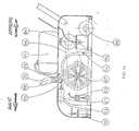
- the machine comprises a frame 1 consisting of a rectangular platform with records 2 on each of its sides to ensure the protection of its organs and possibly the securing of additional devices as will be explained later.
- the frame 1 is provided with rolling means 3 preferably constituted by rollers with a vertical axis which rotate around said axis to make the machine more easily mobile.
- This frame is provided with an operating member 4 which may for example be a handlebar fixed to the box 5 containing the electric power control and regulation members.
- a support 6 of rectangular shape On the frame 1 and substantially at its center with respect to the other elements is fixed by welding or bolting a support 6 of rectangular shape.
- a vacuum group consisting of a motor of known type 8 actuating a suction fan 9 opposite the orifice of the table.
- the casing of the vacuum cleaner group is provided with an upper shoulder 10 which in the working position rests on a vertical hook 11 fixed under the table 7.
- a flange 12 is provided on it.
- a slot in which is inserted a quick coupling system constituted by a threaded rod 13 articulated in a yoke 14 fixed under the table, a bolt or wheel 15 cooperating with the rod 13 comes to block the engine group under the platform.
- This arrangement of the invention has the advantage of making the removal of the extremely fast group in the event of a breakdown or other, the power supply cables being for this purpose got plugs cooperating with a connection socket of the electrical box.
- the hook 11 is preferably constituted by a sheet folded in S, one of the wings of which is welded to the table and the other of which receives the shoulder.
- the width and length of the hook 1 1 depend on the dimensions and the weight of the vacuum cleaner group.
- the casing of the vacuum cleaner group is provided at its base with a port (not shown) for discharging the air sucked in by the fan.
- the engine of said group is an engine of the type known per se without it being necessary to describe its characteristics.
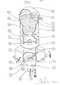
- an enclosure or tank 16 On the table 7 of the support 6 is disposed an enclosure or tank 16, the fnnd of which is pierced with a central orifice opposite the suction group on which a vertical tube 17 is welded.
- the height of the vertical tube 17 through which the vacuum is effected in the enclosure or tank 16 is greater than the height of the walls of said enclosure so that the liquid which is sucked therein cannot penetrate into said tube and drown the vacuum group.
- the tube 17 can be provided with a closure device of the ball valve type constituted as shown in FIG. 1 of an upper bend of the said tube curved at 160 ° so that its orifice is parallel to the tube inside. of the tank, the said cracker being provided with a cage 18 wider than the diameter of the orifice and in which is housed a float 19 shaped to come to rest on its seat by closing the orifice under the thrust of the liquid.
- the float can advantageously consist of a ball of cork or of light synthetic material such as celluloid.
- the top of the tank is closed off by a transparent cover 20 to allow the user to monitor the level of the liquid sucked up.
- the cover has the shape of a spherical cap. It is provided with a horizontal sleeve or end piece 21 for communication with the outside on which the suction duct 22 fits.
- the nozzle 23 of the sleeve 21 is curved downward at 90 ° relative to the axis of the sleeve and it is inclined laterally with respect to said axis so that the discharge of the sucked liquid takes place obliquely which gives said liquid, charged with impurities, dust and others, a swirling movement in the tank.
- a suction shoe as shown in the accompanying drawings or a suction shoe of a type known per se.
- the tank has a lateral nozzle 16A at its lower level connected by a conduit to a device 24 for extracting the liquid contained in the tank.
- the extraction device is an electric water pump of known type fixed on the support 6 or on the side of the tank and the operating control of which actuates a solenoid valve placed on its connection conduit with the enclosure.
- a flexible conduit 25 in one or more connectable sections makes it possible to deliver the liquid discharged to the waste water evacuation network.
- the pump 24 supplied with electrical energy is connected to a level detector 26 of the known plunger type disposed inside the tank which controls the starting of the pump motor when the liquid drawn into the tank reaches a level higher than the determined level fixed taking into account the flow rate of the extraction pump and the suction flow rate and the level stops the extractor when a determined lower level is reached.
- the electrical wiring connecting the level detector and the pump is designed so that the level detector can be disconnected and the pump activated. whatever the level of the liquid, for example by means of a two-way control, one of which interrupts the connection of the detector and the pump motor and the other of which connects the motor to the supply of electrical energy.
- the tank is a removable enclosure fixed to the support table by quick coupling systems not shown and capable of being disconnected from the extraction device on the conduit of which a fitting is mounted. fast.
- a seal consisting of a surface made of a flexible insulating material, such as a rubber sheet, pierced in its center with an orifice opposite the suction, is fixed by gluing. or other process at the table between it and the enclosure.
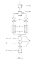
- a device for generating hot water 27 and / or steam connected as shown by a flexible conduit 26 to the cold water supply network and by a conduit 29 supplying an electric pump 30 of known type which sends the liquid under pressure through a line 31 to one or more spray nozzles of the suction shoe.
- the device for generating hot water and / or steam consists of a duct 32, preferably of small section, made of a material which is a good conductor of heat, such as copper for example, folded back on itself in a coil preferably in a vertical plane. to limit the size while obtaining a satisfactory length.
- the calorific power of the two generators is different so that for example one heats the water to around 40 ° and the other to around 70 °.
- solenoid valves 36 mounted on the from the bypass 39 upstream, it is possible to control the supply and the miss in simultaneous or separate operation of the two heaters, the solenoid valves being controlled separately.
- the supply of electrical energy to the heating resistors can be coupled with the closing or opening of the solenoid valves.
- a safety valve 37 is countered at the outlet of the water heating device to remedy any overpressure.
- a solenoid valve 38 mounted downstream of the hot water generator keeps it in charge in the event of a temporary interruption of operation.
- the coil is provided with mcins two resistors with different heat capacity capable of being supplied with electrical energy jointly or separately from each other so that a sufficient heating temperature range is obtained to meet the needs.
- All of the known electrical servo control and electrical safety control members are included in the housing 5 provided with an electric power supply cable not shown.
- the cold water supply duct can be fitted at its end with a weighted non-return valve strainer which allows water to be drawn from a container supplied by the network without direct connection to it.
- the rebcrd 2 of the frame is provided with an electrical connection box, not shown.
- FIGs 5 to 8 is shown a simplified form of the machine according to the invention as described above and whose characteristics follow and are applicable to the machine re - presented in Figure 1 when it operates as a vacuum cleaner Under a frame 1 analogous or on a frame of smaller dimensions in the form of a box provided with rolling members 3 is mounted a vacuum cleaner group 8 - 9 in the same manner as stated above.
- an enclosure made up of a tank 16 and its cover 20.
- peripheral tube 39 which acts as a parechsc. and which also makes it possible to fix the suction shoe.
- the bottom of the tank 16 has a preferably axial and circular orifice aligned with an orifice in the wall of the box and that of the housing of the vacuum cleaner group.
- the cover 24 cooperates with the upper edge of the tank by interlocking, any other arrangement can however be adapted to the machine according to the invention to obtain a sealed closure of the tank by the cover.
- the cover 20 is pierced in the vicinity of its edge with an orifice this passage of the nozzle or sleeve 21 with nozzle 23 for discharging the dust to which the suction pipe 22 is connected.
- the end piece 21 is, as stated above, bent at a right angle so that the nozzle is directed towards the bottom of the tank tangentially to the internal wall of said tank.
- the part of the endpiece oriented towards the bottom of the tank is inclined at an angle relative to the axis of the tank and to one of the generators of said tank or to one of the sides of said tank according to a angle of the order of 15 to 75 °.
- This arrangement of the invention makes it possible, as will be explained above, to direct the flow of air sucked in according to a thecric turn which winds around the internal surface of the tank so that the dust is discharged tangentially to the wall. of the tank.
- a dust receptacle 40 which is constituted by a bag of a textile material impermeable to dust and breathable.
- the bag is provided with a known device for fixing on the upper edge of the enclosure which can be as shown consisting of a washer 41 to which the wall 42 of the bag is welded and which rests on the edge of the enclosure.
- the wall of the bag is separated from the internal wall of the enclosure by a space 43, the volume of the bag being of dimension smaller than the internal volume of the enclosure.
- the volume delimited by the wall 30 of the bag is closed by a bottom 32.
- the width or diameter of the bottom 32 is less than the width or diameter of the orifice of the bag delimited by the washer 29 so that the bag has the shape of an inverted truncated cone whose lower section delimited by the bottom is arranged opposite the suction port of the turbine and the wall 30 of which is inclined with respect to the axis of the enclosure and its plot.
- This form can for example be a pyramidal trunk.
- This arrangement of the invention makes it possible to prevent the wall of the bag from being pressed against the wall of the enclosure during suction.
- this embodiment which is particularly designed for dry cleaning of floors can receive a removable mounted water tank of the type shown in FIG. 1 and in more detail in FIG. 8.
- the suction shoe of the machine according to the invention which is fixed at the end of the flexible conduit 22 can either be movable independently of the machine as defined above, or be fixed in front of it to the box or to the tube 39.
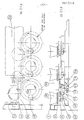
- the suction shoe comprises a chassis, receiving the various components, of substantially rectangular shape produced by welding tubular beams and crosspieces.
- the chassis 44 is covered by a protective cover 45 in the form of a box fixed to the said chassis, preferably by bolting so as to be removable.
- the suction shoe according to the invention is provided with rolling members.
- the rolling members are preferably constituted by parallel rollers 47 mounted between the longitudinal members inside.
- each of the rollers 47 is mounted to rotate freely between the wings 48 of a clevis articulated inside the chassis.
- the blocking in position as a function of the working height is obtained in any known manner, as shown in FIG. 9 a threaded rod 51 perpendicular to the yoke is engaged in an eye of a flange 52 vertical or in an arc welded to the chassis .
- a knurled bolt cooperating with the threaded rod allows locking.
- one of the rollers is driving, the other or the others being freely rotatable.
- the axis of the drive roller is provided with a grooved pulley and the output shaft of an electric motor fixed to the frame is also provided with a grooved pulley connected by a belt to the previous one. .
- the chassis of the device according to the invention as described receives means for projecting the detergent liquid, mechanically acting members on the ground to detach dirt and impurities therefrom, and one or more suction nozzles connected to the machine. by the conduit 22 shown schematically and means for projecting a rinsing fluid which will be sucked in by one or more suction nozzles.
- the means for spraying the detergent liquid are constituted by a nozzle or series of spray nozzles 53 of known type arranged on a ramp inside the cover in its front part but behind the roller and connected by a duct 54 to a pump.
- electric 55 supplied by a conduit 56 to which a reservoir 57 of detergent product is connected.
- the pump is controlled by a push button located on the operating bar, or on the panel of the machine's electrical box.
- the reservoir is removably disposed in wedge in the housing provided on the cover.
- the reservoir will be formed by the commercial container in which the detergent is delivered and the conduit will be a flexible conduit passing through a bore in the cover and which will be immersed in the container through its filling orifice.
- the floor cleaning skewers with mechanical action on the latter comprise a cylindrical brush 58, without doubt median to the chassis, at least one generator of which is in contact with the ground, mounted transversely to the chassis and in the direction of travel of the apparatus.
- the shaft of the brush 58 is rotatably mounted in two bearings fixed respectively on each of the side members.
- the brush is driven by a belt as will be described later.
- a horizontal plate 59 raised relative to the parallel uprights of the frame by means of brackets or gussets welded along an axis transverse to the chassis on each of the side members respectively .
- the ramp of projection nozzles is fixed to the plate by one or more legs 60 (FIG. 9).
- Under the plate 59 is mounted at an alignment preferably parallel to the axis of the brush 58 a series of brushes worm axis - tical actuated in rotation in horizontal plane each of which is driven along a closed path.
- the plate is provided with holes aligned on the same axis.
- each of the bores is wedged a pin 61 by a shoulder 62 and a nut 63.
- a rotary toothed wheel 66 is mounted between the stop shoulder of the journal and the fixed gear 64.
- the toothed wheel 66 is provided with a bore through which the rotary axis 67 of the brush 68 passes, wedged into the bore by a stop shoulder, a ring in a self-lubricating material facilitates the rotation of the axis 67.
- One of the toothed wheels is actuated around the pivot pin 61 in rotation by a tangent motor pinion 70 actuated by means of a bevel gear shown diagrammatically at 71 engaged on the output shaft of the electric motor 72 fixed on the plate.
- An output shaft 73 of the angular gear 35 in the extension of the output shaft of the motor 36 receives a grooved pulley shown diagrammatically at 74 which by a belt 75 rotates a grooved pulley 76 wedged on the shaft brush 58 ( Figure 9).
- the toothed wheel 66 drives the brush 68 along a circular closed-circuit path and by pinion gear 69 and
- the circular trajectory with rotation of each of the brushes 68 in parallel plane contributes by increasing the surface of the ground in contact with each of the brushes to detach the dirt from the ground and to make the machine according to the invention more efficient.
- the timing of each of the brushes is identical on each of the toothed wheels.
- the first suction nozzle 78 connected to the suction duct 22 of the suction device as defined above sucks and removes the dust and dirt detached from the ground by the joint action of the detergent liquid sprayed-in front of the device by the nozzles 53 and rotating brushes.
- Behind the transverse nozzle nozzle 78 is mounted a nozzle or a ramp of projection nozzles 79 fixed transversely to the frame and parallel to the nozzle nozzle by a cross member 80.
- the spray nozzle ramp 79 is in relation to a source of rinsing liquid which can be hot or cold water coming from the reservoir or from the machine according to the invention.
- the rinsing liquid sprayed by the nozzle (s) 79 will have the effect of diluting the detergent which would not have been sucked by the first suction nozzle 79 by preventing it from depositing on the floor.
- the rinsing water, the rest of the diluted detergent and the remaining dust or dirt are sucked in by a second suction nozzle 82 also connected to the suction duct 22 transversely to the chassis and to the direction of advance of the machine.
- the mouth of the nozzle is provided with a nozzle 83 which rubs the ground.
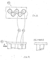
- the suction nozzle 83 consists of a perforated wall 84 closing the mouth of the nozzle and fixed to the latter by any known means, for example by means of a flexible peripheral bead which encloses re the walls of the mouth.
- the wall 84 is provided with one or more rows of vertical conduits 85 opposite its perforations, which are parallel to one another and offset with respect to each other which are made of a flexible material.
- the flexible conduits 85 have a small section, for example of the order of 0.5 to 1 centimeter.
- the suction nozzle 83 is produced by molding a flexible material such as rubber.
- each of the flexible conduits 85 which rubs on the ground is bevelled.
- each of the flexible conduits will adapt by tilting more or less relative to the wall 84 to the reliefs of the ground helped in this by its beveled end.
- This arrangement of the invention makes it possible to obtain the suction of the rinsing water without it being able to be retained by the hollows in the ground in the case of soils having a succession of hollows and reliefs as is the case fear certain floor coverings in synthetic materials likely to be defined by their configuration in honeycombs.
- the shoe has electrical wiring for supply and control of its various organs.
- control can be carried out either from the operating bar fitted with devices for controlling the brushes, the spraying of detergent liquid, the suction and the spraying of the rinsing fluid, or from the control panel. control of the vacuum cleaner as stated above with a connection cable to that of the shoe.
- the shoe according to the invention is fixed to the front of the vacuum cleaner by any known means so that by pushing one, the user pushes the other.
- the device according to the invention is however provided with separate controls for each of the above functions so that it is possible at first to spray detergent, to clean by brushes and to vacuum and secondly during a second pass, rinse with or without mechanical action of the brushes and suction of the rinse fluid.
- FIG 14 is shown another embodiment of the suction shoe intended to be connected to the suction device as defined.
- the chassis constituted by an assembly constituted by the assembly of longitudinal members and crosspieces covered by a cover is provided with a rear rolling member constituted by a roller 86 freely rotatable transversely to the chassis.
- the brush rotates in bearings fixed to the chassis. Its axis is provided with a grooved pulley rotated by a belt 88 cooperating with the output shaft of an electric motor of known type 89 fixed to the chassis
- a nozzle or a ramp of nozzles 92 for spraying a rinsing liquid supplied by a conduit as described above, either from the device for projecting the floor cleaning machine according to the invention , either by the water network of the room to be cleaned, or by a reserve of rinsing water, the duct being in this case next to a solenoid valve and a pump which can be fixed to the chassis between the ramp of projection nozzles and the source of rinse aid.
- the shoe according to the invention is provided with two nozzles 93 and 94 transverse to the chassis joined to the suction duct 22 by forming a bypass 95.
- the suction nozzle 93 comes in front of the cylindrical brush 87 and 18 ramp of spray nozzles 90 of the detergent liquid, the suction nozzle 94 .is placed at the rear of the cylindrical brush 87 and before the projection ramp 92 rinse aid. The lips of each of the tips are above the level of the floor to be cleaned.
- an articulated valve 96 is actuated by a solenoid valve 97 connected to the valve by a rigid rod.
- An axis transverse to the bypass and the ends of which feel fixed on either side of the shoe, for example in holes in the sides of the cover, makes it possible to tilt the assembly 93.94 e so that one or the other of the nozzle tips are in contact with the ground.
- Failover can be achieved by any means.
- cn uses an electromagnet 99 fixed to the chassis and connected to one of the suction nozzles by a rigid rod.
- each of the end pieces is provided with a flexible accordion sleeve which allows by means of a screw, rack or chain system to raise one or the other of the nozzles above the ground.
- Rinsing is carried out by pushing the shoe in the opposite direction, that is to say in reverse after raising the end piece 94, lowering semert of the nozzle 93, obturation by the valve of the nozzle 94 and projection of rinsing liquid, by the rail 92.
- the rinsing liquid is, after the action of the brush, sucked up by the nozzle 93.
- the shoe according to the invention is provided with electrical control means and control of its various organs.
- the different members will be coordinated in operation so that the tilting of the suction nozzles causes, depending on the case, the interruption of the spraying of detergent or the spraying of rinsing liquid and the obturation by the valve of one or the other. other tip.
- the user connects satisfactory lengths of water supply pipes, drainage pipes and suction and projection pipes chosen according to the respective location of the water point, connection to the drainage network wastewater and the area of soil it intends to clean.
- the extraction pump will be started or stopped and the tank will empty in the drainage system worn without special monitoring or handling, which saves a lot of time.
- the user interrupts the water supply, for example by closing the solenoid valve (s), as well as the operation of the hot water generator and the spray pump by electrical interruption.
- the extraction and projection pumps are interchangeable.
- the said bag inflates and stretches, scn bottom bends in a panty curved towards the orifice of the turbine casing, without however the walls of said bag pressing against that of the fan.
- the air flow is directed tarentially to the cylindrical wall of the enclosure and following a turn.
- Said air flow is intercepted by the conical wall of the bag and by the bottom curved in a cap so that it is. returned to the cover which by its conformation in a spherical cap plays a role of deflector of said air flow which performs inside the bag an elliptical swirling movement.
- the vacuum cleaner according to the inversion can also receive a water tank shown in Figure 1 deté a central suction duct, said tank being fixed by the quick coupling system.
- the machine according to the invention had the advantage of being versatile since it can be used as a machine for cleaning floors by wet or dry process and its suction shoe in its two embodiments makes it possible to produce a effective floor cleaning.
Landscapes
- Engineering & Computer Science (AREA)
- Mechanical Engineering (AREA)
- Nozzles For Electric Vacuum Cleaners (AREA)
Priority Applications (1)
| Application Number | Priority Date | Filing Date | Title |
|---|---|---|---|
| AT80400297T ATE8963T1 (de) | 1979-03-05 | 1980-03-04 | Trockenstaubsauger fuer bodenflaechen. |
Applications Claiming Priority (6)
| Application Number | Priority Date | Filing Date | Title |
|---|---|---|---|
| FR7906306A FR2450591A1 (fr) | 1979-03-05 | 1979-03-05 | Machine pour le nettoyage des sols par projection de liquide et/ou de vapeur et par aspiration |
| FR7906306 | 1979-03-05 | ||
| FR7906308A FR2450592B1 (fr) | 1979-03-05 | 1979-03-05 | Appareil de nettoyage des sols du type sabot suceur |
| FR7906307A FR2450593A1 (fr) | 1979-03-05 | 1979-03-05 | Machine a nettoyer les sols ou autres parois du type aspirateur |
| FR7906308 | 1979-03-05 | ||
| FR7906307 | 1979-03-05 |
Publications (3)
| Publication Number | Publication Date |
|---|---|
| EP0017519A2 true EP0017519A2 (de) | 1980-10-15 |
| EP0017519A3 EP0017519A3 (en) | 1981-05-13 |
| EP0017519B1 EP0017519B1 (de) | 1984-08-15 |
Family
ID=27250905
Family Applications (1)
| Application Number | Title | Priority Date | Filing Date |
|---|---|---|---|
| EP19800400297 Expired EP0017519B1 (de) | 1979-03-05 | 1980-03-04 | Trockenstaubsauger für Bodenflächen |
Country Status (2)
| Country | Link |
|---|---|
| EP (1) | EP0017519B1 (de) |
| DE (1) | DE3068929D1 (de) |
Cited By (13)
| Publication number | Priority date | Publication date | Assignee | Title |
|---|---|---|---|---|
| EP0032654A3 (de) * | 1980-01-14 | 1981-08-05 | NOVUM - Novità in Elettrodomestica Srl | Flächenwaschgerät |
| EP0286328A1 (de) * | 1987-04-03 | 1988-10-12 | Rotowash Scandinavia Aps | Gerät zum Nassreinigen einer Fussbodenfläche oder Wandfläche |
| FR2661339A1 (fr) * | 1990-04-26 | 1991-10-31 | Galliot Bernard | Nettoyeur autolaveur ondulatoire a vapeur. |
| DE4202987A1 (de) * | 1992-02-03 | 1993-08-05 | Hako Gmbh & Co | Fahrbare nassreinigungsmaschine |
| EP0800783A3 (de) * | 1996-03-01 | 1997-10-22 | Unilever Nv | |
| WO1998002081A1 (en) * | 1996-07-12 | 1998-01-22 | Shop Vac Corporation | Self-evacuating vacuum cleaner |
| EP0951858A1 (de) * | 1998-04-22 | 1999-10-27 | Unilever N.V. | Bodenreinigungsmaschine |
| EP1044645A3 (de) * | 1999-04-15 | 2002-12-04 | Alto U.S. Inc. | Maschine zur Absaugung von Flüssigkeiten und Verfahren zur Reinigung von Bodenflächen |
| US6529605B1 (en) | 2000-04-14 | 2003-03-04 | Harman International Industries, Incorporated | Method and apparatus for dynamic sound optimization |
| US7302062B2 (en) | 2004-03-19 | 2007-11-27 | Harman Becker Automotive Systems Gmbh | Audio enhancement system |
| CN109157155A (zh) * | 2018-08-31 | 2019-01-08 | 珠海格力电器股份有限公司 | 一种吸尘器及其控制方法 |
| CN113171035A (zh) * | 2021-04-25 | 2021-07-27 | 廖聪钱 | 一种医疗用过道消毒装置 |
| CN114766967A (zh) * | 2017-09-13 | 2022-07-22 | 阿尔弗雷德·卡赫欧洲两合公司 | 表面清洁器 |
Families Citing this family (10)
| Publication number | Priority date | Publication date | Assignee | Title |
|---|---|---|---|---|
| US5966775A (en) | 1996-07-12 | 1999-10-19 | Shop Vac Corporation | Self-evacuating vacuum cleaner |
| US6009596A (en) | 1996-07-12 | 2000-01-04 | Shop Vac Corporation | Self-evacuating vacuum cleaner |
| US5918344A (en) | 1996-07-12 | 1999-07-06 | Shop Vac Corporation | Self-evacuating vacuum cleaner |
| US6112366A (en) | 1999-01-20 | 2000-09-05 | Shop Vac Corporation | Outlet priming self-evacuation vacuum cleaner |
| EP1833163B1 (de) | 2004-07-20 | 2019-12-18 | Harman Becker Automotive Systems GmbH | Audioverbesserungssystem und -verfahren |
| US8170221B2 (en) | 2005-03-21 | 2012-05-01 | Harman Becker Automotive Systems Gmbh | Audio enhancement system and method |
| DE602005015426D1 (de) | 2005-05-04 | 2009-08-27 | Harman Becker Automotive Sys | System und Verfahren zur Intensivierung von Audiosignalen |
| DE202012010452U1 (de) * | 2012-10-30 | 2014-01-31 | Wetrok Ag | Bodenreinigungsvorrichtung |
| DE202012010450U1 (de) * | 2012-10-30 | 2014-01-31 | Wetrok Ag | Bodenreinigungsvorrichtung |
| US9107556B2 (en) | 2012-10-30 | 2015-08-18 | Wetrok Ag | Floor cleaning apparatus |
Family Cites Families (27)
| Publication number | Priority date | Publication date | Assignee | Title |
|---|---|---|---|---|
| FR435755A (fr) * | 1910-10-31 | 1912-03-09 | Eberhard Seger | Appareil de nettoyage par le vide |
| GB113089A (en) * | 1917-01-30 | 1918-10-17 | Halla Floyd Gray | Improvements in Carpet Washing and Rinsing Machines. |
| US1975380A (en) * | 1932-05-31 | 1934-10-02 | Charles A Streich | Portable rug washing and cleaning device |
| US2030133A (en) * | 1934-02-14 | 1936-02-11 | Gladys C Baxter | Vacuum cleaner |
| DE894308C (de) * | 1943-01-01 | 1953-10-22 | Siemens Ag | Staubsauger |
| DK67806C (da) * | 1947-01-17 | 1948-10-18 | Arthur Lau | Maskine til brug såvel ved kemisk rensning af gulvtæpper som ved vask, rensning og boning af gulve. |
| US2539195A (en) * | 1950-05-02 | 1951-01-23 | Gen Electric | Inlet dirt deflector and filter arrangement for suction cleaners |
| US2731659A (en) * | 1952-12-08 | 1956-01-24 | Coplen George | Floor scrubbing machine |
| FR1083663A (fr) * | 1953-06-29 | 1955-01-11 | Poche fongible pour aspirateurs de poussières | |
| US3540072A (en) * | 1964-08-03 | 1970-11-17 | Sunbeam Corp | Floor conditioner |
| US3262146A (en) * | 1964-09-08 | 1966-07-26 | Fred E Hays | Steam-vacuum generator for rug and upholstery cleaning |
| US3343199A (en) * | 1965-01-18 | 1967-09-26 | Louis C Nolte | Cleaning device |
| US3496592A (en) * | 1969-04-24 | 1970-02-24 | Judson O Jones | Portable apparatus for cleaning and partially drying carpets |
| US4114229A (en) * | 1971-06-30 | 1978-09-19 | Clarke-Gravely Corporation | Surface cleaning apparatus |
| US3951597A (en) * | 1971-12-08 | 1976-04-20 | Steamatic, Inc. | Method of dry cleaning fabrics |
| US3774260A (en) * | 1972-01-31 | 1973-11-27 | Carpetech Corp | Vacuum pick-up system |
| DE2227935A1 (de) * | 1972-06-08 | 1973-12-20 | Rolf Reichert | Sauggeraet insbesondere fuer industrielle zwecke |
| GB1445093A (en) * | 1972-08-26 | 1976-08-04 | Carpetronic Ltd | Machines for cleaning carpets and the like |
| US3896521A (en) * | 1973-03-27 | 1975-07-29 | Parise & Sons Inc | Home cleaning system |
| FR2264510A1 (en) * | 1974-03-18 | 1975-10-17 | Chazalon Jacques | Water spray cleaner and vacuum cleaner - has pump connected to air or spray circuit controlled by electromagnetic valve |
| CH575748A5 (en) * | 1974-12-17 | 1976-05-31 | Baehni Heinz | Multi purpose cleaning machine - has drum containing dual suction motors and liquid container suspended above shampoo |
| US4014067A (en) * | 1975-06-20 | 1977-03-29 | Charles Ross Bates | Carpet cleaning implement |
| FR2328439A1 (fr) * | 1975-10-23 | 1977-05-20 | Juif Gilbert | Perfectionnements aux machines pour traiter des surfaces planes, notamment pour nettoyer des sols |
| NL7513513A (en) * | 1975-11-19 | 1977-05-23 | Rossen Arie Van | Carpet cleaning machine with spray head - uses detachable vacuum cleaner to serve suction device |
| US4046989A (en) * | 1976-06-21 | 1977-09-06 | Parise & Sons, Inc. | Hot water extraction unit having electrical immersion heater |
| US4167800A (en) * | 1977-03-28 | 1979-09-18 | Herbert Tribolet | Unitary wet and dry vacuum cleaner |
| US4139922A (en) * | 1977-08-19 | 1979-02-20 | Chester Fitch | Carpet cleaning device |
-
1980
- 1980-03-04 DE DE8080400297T patent/DE3068929D1/de not_active Expired
- 1980-03-04 EP EP19800400297 patent/EP0017519B1/de not_active Expired
Cited By (17)
| Publication number | Priority date | Publication date | Assignee | Title |
|---|---|---|---|---|
| EP0032654A3 (de) * | 1980-01-14 | 1981-08-05 | NOVUM - Novità in Elettrodomestica Srl | Flächenwaschgerät |
| EP0286328A1 (de) * | 1987-04-03 | 1988-10-12 | Rotowash Scandinavia Aps | Gerät zum Nassreinigen einer Fussbodenfläche oder Wandfläche |
| US4845794A (en) * | 1987-04-03 | 1989-07-11 | Rotowash Scandinavia | Apparatus for wet cleaning a floor or wall surface |
| FR2661339A1 (fr) * | 1990-04-26 | 1991-10-31 | Galliot Bernard | Nettoyeur autolaveur ondulatoire a vapeur. |
| DE4202987A1 (de) * | 1992-02-03 | 1993-08-05 | Hako Gmbh & Co | Fahrbare nassreinigungsmaschine |
| EP0800783A3 (de) * | 1996-03-01 | 1997-10-22 | Unilever Nv | |
| US5933911A (en) * | 1996-03-01 | 1999-08-10 | Diversey Lever, Inc. | Apparatus for cleaning a ground |
| WO1998002081A1 (en) * | 1996-07-12 | 1998-01-22 | Shop Vac Corporation | Self-evacuating vacuum cleaner |
| EP0951858A1 (de) * | 1998-04-22 | 1999-10-27 | Unilever N.V. | Bodenreinigungsmaschine |
| US6105203A (en) * | 1998-04-22 | 2000-08-22 | Diversey Lever, Inc. | Floor cleaning machine |
| EP1044645A3 (de) * | 1999-04-15 | 2002-12-04 | Alto U.S. Inc. | Maschine zur Absaugung von Flüssigkeiten und Verfahren zur Reinigung von Bodenflächen |
| US6529605B1 (en) | 2000-04-14 | 2003-03-04 | Harman International Industries, Incorporated | Method and apparatus for dynamic sound optimization |
| US7302062B2 (en) | 2004-03-19 | 2007-11-27 | Harman Becker Automotive Systems Gmbh | Audio enhancement system |
| CN114766967A (zh) * | 2017-09-13 | 2022-07-22 | 阿尔弗雷德·卡赫欧洲两合公司 | 表面清洁器 |
| CN114766967B (zh) * | 2017-09-13 | 2024-03-19 | 阿尔弗雷德·卡赫欧洲两合公司 | 表面清洁器 |
| CN109157155A (zh) * | 2018-08-31 | 2019-01-08 | 珠海格力电器股份有限公司 | 一种吸尘器及其控制方法 |
| CN113171035A (zh) * | 2021-04-25 | 2021-07-27 | 廖聪钱 | 一种医疗用过道消毒装置 |
Also Published As
| Publication number | Publication date |
|---|---|
| DE3068929D1 (en) | 1984-09-20 |
| EP0017519B1 (de) | 1984-08-15 |
| EP0017519A3 (en) | 1981-05-13 |
Similar Documents
| Publication | Publication Date | Title |
|---|---|---|
| EP0017519B1 (de) | Trockenstaubsauger für Bodenflächen | |
| EP2330956B1 (de) | Schaber für glatte oberflächen | |
| WO2011073595A1 (fr) | Appareil nettoyeur de surface immergée à cabrage hydraulique | |
| FR2680962A1 (fr) | Extracteur a vide et ensemble de reservoirs pour cet extracteur. | |
| EP4119728B1 (de) | Industrielle kehrmaschine, die mit einer perfektionierten reinigungsvorrichtung für ihren luftfilter versehen ist | |
| EP0187174A1 (de) | Fahrbare Vorrichtung zum Reinigen von Behältern, z.B. Müllbehältern | |
| EP1629163B1 (de) | Wasserzirkulationseinheit mit erhöhtem durchsatz für schwimmbecken und diese enthaltende filtereinheit | |
| EP0215084B1 (de) | Scheuervorrichtung zur chemisch-mechanischen beseitigung von bodenhaftenden rückständen und deren anwendung bei der bürstung und verteilung von flüssigprodukten | |
| EP1518612A1 (de) | Waschanlage für einen Rost aufweisende Gegenstände | |
| EP0714241B1 (de) | Einrichtung zum kontinuierlichen waschen von produkten, insbesondere pflanzengut | |
| FR2929488A1 (fr) | Appareil de nettoyage de terrain engazonne | |
| WO2023198974A1 (fr) | Suceur d'aspirateur équipé d'un dispositif de nettoyage à la vapeur | |
| EP1743073A1 (de) | Bewegliche maschine zum spritzen eines flüssigkeitsstrahls, beispielsweise farbe, auf eine feststehende horizontale fläche zur bildung einer linie | |
| US20060010626A1 (en) | Portable surface treating apparatus | |
| WO2008129161A2 (fr) | Transporteur pneumatique pour la distribution de produits fibreux et autres par tuyaux | |
| EP0681677B1 (de) | Zentrifuge für schüttgut | |
| FR2727880A1 (fr) | Dispositif de nettoyage de tuyaux | |
| FR2952293A1 (fr) | Appareil de lavage des sols a la vapeur par frottement utilisant une piece a frotter, muni d'un dispositif de nettoyage de cette piece a frotter, en cours d'utilisation | |
| EP0500903A1 (de) | Rotierende trocken composttoilette. | |
| FR2704741A1 (fr) | Dispositif de nettoyage de surface par projection de vapeur avec ou sans aspiration. | |
| FR2968019A1 (fr) | Vehicule d'entretien de voirie equipe d'un dispositif d'aspiration | |
| FR2882912A1 (fr) | Nettoyeur de sol integral | |
| FR2511055A1 (fr) | Motocycle pour le nettoyage des sols | |
| FR2836363A1 (fr) | Machine a nettoyer les sols | |
| FR2666725A1 (fr) | Porte de lavage d'une machine a baratter. |
Legal Events
| Date | Code | Title | Description |
|---|---|---|---|
| PUAI | Public reference made under article 153(3) epc to a published international application that has entered the european phase |
Free format text: ORIGINAL CODE: 0009012 |
|
| AK | Designated contracting states |
Designated state(s): AT BE CH DE GB IT LU NL SE |
|
| PUAL | Search report despatched |
Free format text: ORIGINAL CODE: 0009013 |
|
| AK | Designated contracting states |
Designated state(s): AT BE CH DE GB IT LU NL SE |
|
| 17P | Request for examination filed |
Effective date: 19810526 |
|
| ITF | It: translation for a ep patent filed | ||
| GRAA | (expected) grant |
Free format text: ORIGINAL CODE: 0009210 |
|
| AK | Designated contracting states |
Designated state(s): AT BE CH DE GB IT LU NL SE |
|
| REF | Corresponds to: |
Ref document number: 8963 Country of ref document: AT Date of ref document: 19840915 Kind code of ref document: T |
|
| REF | Corresponds to: |
Ref document number: 3068929 Country of ref document: DE Date of ref document: 19840920 |
|
| PG25 | Lapsed in a contracting state [announced via postgrant information from national office to epo] |
Ref country code: LU Free format text: LAPSE BECAUSE OF NON-PAYMENT OF DUE FEES Effective date: 19850331 Ref country code: CH Effective date: 19850331 Ref country code: BE Effective date: 19850331 |
|
| PGFP | Annual fee paid to national office [announced via postgrant information from national office to epo] |
Ref country code: NL Payment date: 19850331 Year of fee payment: 6 |
|
| PLBE | No opposition filed within time limit |
Free format text: ORIGINAL CODE: 0009261 |
|
| STAA | Information on the status of an ep patent application or granted ep patent |
Free format text: STATUS: NO OPPOSITION FILED WITHIN TIME LIMIT |
|
| 26N | No opposition filed | ||
| PGFP | Annual fee paid to national office [announced via postgrant information from national office to epo] |
Ref country code: AT Payment date: 19850731 Year of fee payment: 6 |
|
| BERE | Be: lapsed |
Owner name: BEGARIE AUGUSTE Effective date: 19850304 |
|
| GBPC | Gb: european patent ceased through non-payment of renewal fee | ||
| REG | Reference to a national code |
Ref country code: CH Ref legal event code: PL |
|
| PG25 | Lapsed in a contracting state [announced via postgrant information from national office to epo] |
Ref country code: DE Effective date: 19851203 |
|
| PG25 | Lapsed in a contracting state [announced via postgrant information from national office to epo] |
Ref country code: AT Effective date: 19860304 |
|
| PG25 | Lapsed in a contracting state [announced via postgrant information from national office to epo] |
Ref country code: SE Effective date: 19860305 |
|
| PG25 | Lapsed in a contracting state [announced via postgrant information from national office to epo] |
Ref country code: NL Effective date: 19861001 |
|
| NLV4 | Nl: lapsed or anulled due to non-payment of the annual fee | ||
| PG25 | Lapsed in a contracting state [announced via postgrant information from national office to epo] |
Ref country code: GB Effective date: 19881118 |
|
| EUG | Se: european patent has lapsed |
Ref document number: 80400297.0 Effective date: 19870223 |