EP0017547A1 - Détecteur de proximité et son utilisation - Google Patents
Détecteur de proximité et son utilisation Download PDFInfo
- Publication number
- EP0017547A1 EP0017547A1 EP19800400376 EP80400376A EP0017547A1 EP 0017547 A1 EP0017547 A1 EP 0017547A1 EP 19800400376 EP19800400376 EP 19800400376 EP 80400376 A EP80400376 A EP 80400376A EP 0017547 A1 EP0017547 A1 EP 0017547A1
- Authority
- EP
- European Patent Office
- Prior art keywords
- antenna
- signals
- sections
- door
- signal
- Prior art date
- Legal status (The legal status is an assumption and is not a legal conclusion. Google has not performed a legal analysis and makes no representation as to the accuracy of the status listed.)
- Granted
Links
Images

Classifications
-
- B—PERFORMING OPERATIONS; TRANSPORTING
- B66—HOISTING; LIFTING; HAULING
- B66B—ELEVATORS; ESCALATORS OR MOVING WALKWAYS
- B66B13/00—Doors, gates, or other apparatus controlling access to, or exit from, cages or lift well landings
- B66B13/24—Safety devices in passenger lifts, not otherwise provided for, for preventing trapping of passengers
- B66B13/26—Safety devices in passenger lifts, not otherwise provided for, for preventing trapping of passengers between closing doors
-
- G—PHYSICS
- G01—MEASURING; TESTING
- G01V—GEOPHYSICS; GRAVITATIONAL MEASUREMENTS; DETECTING MASSES OR OBJECTS; TAGS
- G01V3/00—Electric or magnetic prospecting or detecting; Measuring magnetic field characteristics of the earth, e.g. declination, deviation
- G01V3/08—Electric or magnetic prospecting or detecting; Measuring magnetic field characteristics of the earth, e.g. declination, deviation operating with magnetic or electric fields produced or modified by objects or geological structures or by detecting devices
-
- G—PHYSICS
- G08—SIGNALLING
- G08B—SIGNALLING SYSTEMS, e.g. PERSONAL CALLING SYSTEMS; ORDER TELEGRAPHS; ALARM SYSTEMS
- G08B13/00—Burglar, theft or intruder alarms
- G08B13/22—Electrical actuation
- G08B13/24—Electrical actuation by interference with electromagnetic field distribution
- G08B13/2491—Intrusion detection systems, i.e. where the body of an intruder causes the interference with the electromagnetic field
Definitions
- the invention relates to a proximity sensor for detecting the presence of a body at a certain distance from an element such as for example an intruder near an entrance to a building or an obstacle. on the path of a mobile such as a press tool.
- this detector Although not exclusively, it nevertheless relates more particularly to the application of this detector to the vertical edges of a door with automatic closure and in particular to landing doors and / or elevator cabs and hoists.
- the aim is obviously that the presence of a person or an object liable to be struck when the door is closed is detected while the edge of the door is inked at a certain distance, so that from the signal from this detector, we can then control the blocking of the poite and therefore interrupt its closing or even order its reopening if the level of this signal exceeds a certain threshold.
- detectors of this type are well suited to solve the problem of detecting an obstacle to closing the doors.
- the processing of the signals from the antenna sections takes place by balancing in a bridge circuit (US Pat. No. 3,018,851 and 2,720,284), and it follows that the system is very unstable and of complex adjustment. This is why a result which the invention aims to obtain is a very stable detector, of simple adjustment and which, moreover, is inexpensive and easy to adapt to the element close to which it is desired to detect any approach to a body and for example on specially designed or existing doors.
- the subject of the invention is a detector of the type mentioned above, in particular characterized in that the sections of the antenna are each connected to means for rectifying the positive and negative half-waves of the alternating signal which it receives. , these means each delivering in separate circuits two signals called first and second signal and in that all the circuits of the first signals, which are derived from positive half-waves, are connected to one of the inputs of an adder under the control of '' a door actually sending to this header only the first signal from the section with the highest voltage, while all the circuits of the second signals, which are derived from negative half-waves, are connected to the other input of this adder under the control of a limiter, so as not to send this input as the sum of the second signals divided by the number of rods.
- the device comprises an oscillator 1 at very low frequency (FIG. 3), for example of eight kilohertz and of low power, the emission point 2 of which is connected to the ground 3 to emit incidentally a sinusoidal signal of constant amplitude and / or frequency. Therefore, any person approaching being necessarily more or less coupled to the earth, it is supplied with energy which it radiates in its immediate environment in the form of electromagnetic waves. It is the same for any metallic body connected to earth, such as in this nonlimiting example of an elevator door 4, the two panels 5, 6 may be so due to their connection to earth at 7 , 8. The edges 11, 12 of the panels then receive, after the interposition of a seal 9, 10 of insulating material of any known type, a metal screen 13, 14, for example of aluminum.
- a seal 9, 10 of insulating material of any known type a metal screen 13, 14, for example of aluminum.
- These screens 13, 14 are, by junctions. 13, 16, 17, connected at 18 to the reference potential of the transmitter 1.
- each door edge receives an antenna 19, 20, split into several independent sections, for example into six sections 19 a, at 19 f ( Figure 2).
- These sections of antenna receive only the waves reflected by certain bodies and especially the waves radiated by others, which are more or less coupled to the earth or which restore part of their induced voltage.
- this foreign body radiates or reflects a field of higher value, which then modifies the reception intensity of this antenna section and of its output signal, the more strongly the closer the foreign body is.
- the output signals can obviously be adjusted to a predetermined value so that, in the absence of foreign bodies, they are all equal.
- the signal is presented to two logic gates 23, 24 (FIG. 1) like triggers adjusted to different thresholds, the first commanding through a delay circuit 25 a relay 26 for blocking the doors, while the other also controls, through a delay circuit 27, the relay 28 for reopening the doors.
- a timed circuit 29 detects the persistence of the blocking or reopening commands beyond a preset time and activates an alarm.
- the antenna sections are connected to means for picking up two separate related signals, one with the peak value of the voltage induced on the section with the highest voltage, the other with the average value of the voltages of all the sections, as well as with means for comparing these two signals.
- these sampling and analysis means comprise, first of all rectifying means 36, 37, positive and negative half-waves of the alternating signal which it receives, such as diodes.
- All the circuits 38 of the first signals which therefore come from positive half-waves, are connected to one 40 of the inputs of a comparator 21 such as an operational amplifier and this under the control of a gate 30 (FIG. 2), in order to effectively send to this input only the value of the first signal A, or B, or C, or D, or E, or F coming from the section whose voltage is the highest.
- a comparator 21 such as an operational amplifier
- all the circuits 39 of the second signals which originate from negative half-waves are connected to the other input 41 of the comparator 21 under the control of a limiter 31 such as a resistor, so as to effectively send only this input to this input.
- a limiter 31 such as a resistor
- the comparator then adds these two distinct signals and, during the initial adjustment mentioned above, which is carried out in the absence of a foreign body, the signals A to F and a to f of antenna sections being adjusted to be all identical, the detections on the positive and negative half-waves balance and the output signal Y is zero.
- the door 30 is formed by the diodes 36 which in known manner allow only the peak value to pass, provided that they are not otherwise, due to their connection by their bases, blocked by a higher signal from another diode.
- the output signal Y of the comparator 21 has the advantage of being accentuated and above all, when the balance is achieved, of being very little influenced by external operating conditions, resulting in high detection stability.
- two antennas 19, 20 are used in several sections, but obviously in the case of a door with a single mobile panel, there will be no than an antenna 19, but on the other hand, there will be a screen on the two vertical edges delimiting the opening either on the edge of the movable panel and on the edge of the fixed or upright panel, so that the upright does not radiate directly towards the antenna, when the door is almost closed.
- the metal screen produces a U-shaped profile covering the edge of the door panel or of the upright and externally carrying a strip 32, 33 hollowed out to accommodate the antenna and then closed at its front part by a plate 34 , 35 permeable to waves.
- the strips 32, 33 housing the antennas of the two panels of a door are less than half the width of that of the screen and are offset relative to each other: they therefore each adjoin one of the faces of the panel and are placed one beside the other in the closed door position.
Landscapes
- Physics & Mathematics (AREA)
- Electromagnetism (AREA)
- General Physics & Mathematics (AREA)
- Engineering & Computer Science (AREA)
- Remote Sensing (AREA)
- Life Sciences & Earth Sciences (AREA)
- General Life Sciences & Earth Sciences (AREA)
- Geology (AREA)
- Environmental & Geological Engineering (AREA)
- Geophysics (AREA)
- Geophysics And Detection Of Objects (AREA)
- Radar Systems Or Details Thereof (AREA)
- Elevator Door Apparatuses (AREA)
- Power-Operated Mechanisms For Wings (AREA)
- Switches That Are Operated By Magnetic Or Electric Fields (AREA)
- Indicating And Signalling Devices For Elevators (AREA)
- Control Of Vending Devices And Auxiliary Devices For Vending Devices (AREA)
- Electronic Switches (AREA)
Abstract
Description
- L'invention se rapporte à un détecteur de proximité en vue de déceler la présence d'un corps à une certaine distance d'un élément comme par exemple d'un intrus à proximité d'une entrée d'un bâtiment ou d'un obstacle sur la trajectoire d'un mobile tel 1' outil d'une presse.
- Bien que non exclusivement, elle vise toutefois plus particulièrement l'application de ce détecteur aux bords verticaux d'une porte à fermeture automatique et notamment aux portes palières et/ou des cabines d'ascenseurs et monte- charges. Dans cette application particulière, le but est évidemment que la présence d'une personne ou d'un objet susceptible d'être heurté lors de la fermeture de la porte soit détecté alors que le bord de la porte en est encre à une certaine distance, pour qu'à partir du signal issu de ce détecteur, on puisse alors commander le blocage de la poite et donc interrompre sa fermeture voire même commander sa réouverture si le niveau de ce signal dépasse un certain seuil.
- Pour cette application à la réouverture de portes d'ascenseurs, il existe déjà divers dispositifs tendant à limiter sinon éviter les dommages tels que notamment :
- - des détecteurs d'effort, qui toutefois ne décèlent la présence de la personne ou de l'objet qu'en le heurtant
- - des palpeurs pneumatiques, qui malheureusement, lorsqu'ils sont sensibles sont aussi très fragiles
- - des cellules photoélectriques, mais dont la zone de sensibilité est limitée au faisceau balayé par le rayon lumineux
- - des radars, qui, outre un coût très élevé, ont l'inconvénient de ne pas être sélectifs.
- On connaît également des détecteurs de proximité comprenant (brevet US 3.018.851):
- - un oscillateur à très basse fréquence et de faible puissance dont le point d'émission est relié à la terre pour y émettre un signal d'amplitude et de fréquence constantes
- - au moins une antenne de réception, scindée en plusieurs tronçons indépendants, fixée sur la partie de l'élément dont on surveille l'abord mais située en dehors du champ ; de rayonnement direct des éléments qui environnent cette partie et qui sont couplés à la terre mais qui conservent une distance fixe par rapport à ladite partie
- - un circuit de traitement de la tension induite à chaque tronçon d'antenne de réception par les ondes aussi bien réfléchies que rayonnées par les corps qui environnent l'antenne, afin d'émettre un signal final dont l'intensité sera modifiée en fonction de l'existence d'un corps étranger à proximité de ladite antenne.
- Fonctionnant par lecture des différences de couplage capacitif à la terre de chaque tron çon d'antenne, les détecteurs de ce type sont bien adaptés pour résoudre le problème de la détection d'un obstacle à la fermeture des portes. Malheureusement, dans les détecteurs de ce type connus à ce jour, le traitement des signaux issus des tronçons d' antenne s'opère par équilibrage dans un circuit en pont (brevet US 3.018.851 et 2.720.284), et il en résulte que le système est très instable et de réglage complexe. C'est pourquoi, un résultat que l'invention vise à obtenir est un détecteur très stable, de réglage simple et qui par ailleurs, est peu coûteux et facile à adapter sur l'élément à proximité duquel on veut déceler toute approche d'un corps et par exemple sur des portes conçues spécialement ou existantes.
- Pour cela, l'invention a pour objet un détecteur du type cité plus haut, notamment caractérisé en ce que les tronçons de l'antenne sont raccordés chacun à des moyens de redressement des alternances positives et néga- tives du signal alternatif qu'il reçoit, ces moyens délivrant chacun dans des circuits distincts deux signaux dits premier et deuxième signal et en ce que tous les circuits des premiers signaux, lesquels sont issus des alternances positives, sont raccordés à l'une des entrées d'un sommateur sous le contrôle d'une porte n'envoyant effectivement à cette enttée que le premier signal issu du tronçon dont la tension est la plus élevée,alors que tous les circuits des deuxièmes signaux, lesquels sont issus des alternances négatives, sont raccordés à l'autre entrée de ce sommateur sous le contrôle d'un limiteur, afin de n'envoyer à cette entrée que la somme des seconds signaux divisés par le nombre de trongons.
- Elle a également pour objet les éléments pourvus de ce détecteur.
- Elle sera bien comprise à l'aide de la description ci-après faite, à titre d'exemple non limitatif, en regard du dessin ci-annexé qui représente, dans son application à une porte d'ascenseur :
- - figure 1 : le schéma bloc de l'ensemble recevant les signaux
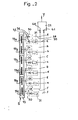
- - figure 2 : en vue symbolique, un circuit de traitement des signaux issus des antennes
- - figure 3 : vus en coupe, les bords de la porte pourvue du détecteur.
- En se reportant au dessin, on voit que le dispositif comprend un oscillateur 1 à très basse fréquence (figure 3), par exemple de huit kilohertz et de faible puissance dont le point d'émission 2 est relié à la terre 3 pour y émettre accessoirement un signal sinusoïdal d'amplitude et/de frequence constantes. De ce fait, toute personne s'approchant étant nécessairement plus ou moins couplée à la terre, elle est alimentée en énergie qu'elle rayonne dans son environnement immédiat sous la forme d'ondes électro-magnétiques. Il en est de même de tout corps métallique raccordé à la terre, tel que dans cet exemple non limitatif d'une porte 4 d'ascenseur, peuvent l'être les deux panneaux 5,6 du fait de leur raccordement à la terre en 7,8. Les bords 11,12 des panneaux reçoivent alors après interposition d'un joint 9,10 en matériau isolant de tout type connu, un écran métallique 13,14, par exemple en aluminium.
- Ces écrans 13,14 sont, par des jonctions .13,16,17,reliés en 18 au potentiel de référence de l'émetteur 1.
- Devant chaque écran 13,14 et donc en dehors du champ de rayonnement direct des panneaux 5,6, chaque bord de porte reçoit une antenne 19, 20, scindée en plusieurs tronçons indépendants, par exemple en six tronçons 19 a, à 19 f (figure 2).
- Ces tronçons d'anten ne ne reçoivent que les ondes réfléchies par certains corps et surtout les ondes rayonnées par d'autres, qui sont plus ou moins couplés à la terre ou qui restituent une partie de leur tension induite.
- En l'absence dans le champ d'ondes, d'usagers ou d'objets et en général de tout corps étranger, les ondes ainsi réfléchies et/ou rayonnées par les parties fixées à demeure agissent sur les divers tronçons d'antenne dans des proportions qui restent constantes.
- Dès qu'un corps étranger est à proximité d'un des tronçons d'antenne, sur ce tronçon, ce corps étranger rayonne ou réfléchit un champ de valeur supérieure, ce qui modifie alors l'intensité de réception de ce tronçon d'antenne et de son signal de sortie et ce d'autant plus fortement que le corps étranger est plus proche.
- C'est le traitement, dans un analyseur 21, 22 des variations de proportion des signaux de sortie des tronçons d'antenne qui permet de détecter et d' apprécier la proximité plus ou moins immédiate de ce corps étranger.
- Avant analyse, les signaux de sortie peuvent évidemment être réglés à une valeur prédéterminée pour, en l'absence de corps étrangers, être tous égaux.
- Pour apprécier la distance de l'objet et donc l'urgence d'une intervention, le signal est présenté à deux portes logiques 23, 24 (figure 1) tels des triggers réglés à des seuils différents, la première commandant au travers d'un circuit de retard 25 un relais 26 de blocage des portes, alors que l'autre commande également au travers d'un circuit de retard 27 le relais 28 de réouverture des portes.
- Un circuit temporisé 29 décèle la persistance des commandes de blocage ou de réouverture au-delà d'un temps préréglé et actionne une alarme.
- Selon une caractéristique de l'invention les tronçons d'antenne sont raccordés à des moyens de prélèvement de deux signaux distincts en rapport, l'un avec la valeur crête de la tension induite sur le tronçon dont la tension est la plus élevée, l'autre avec la valeur moyenne des tensions de tous les tronçons, ainsi qu'à des moyens de comparaison de ces deux signaux.
- Dans un mode préféré de réalisation, ces moyens de prélèvement et d'analyse comprennent, tout d'abord des moyens 36, 37 de redressement, des alternances positives et négatives du signal alternatif qu'il reçoit, tels que des diodes.
- Ces moyens 36, 37 délivrent, dans des circuits 38, 39 distincts, deux signaux dits :
- - premier signal "A" à "F" pour les alternances positives,
- - deuxième signal "a" à "f" pour les alternances négatives, avec, évidemment, en l'absence de corps étrangers, et ce, grâce à un ajustement initial; a = A, b = B, c = C, d = D, f = F.
- Tous les circuits 38 des premiers signaux, lesquels sont donc issus des alternances positives, sont raccordés à l'une 40 des entrées d'un comparateur 21 tel un amplificateur opérationnel et ce sous le contrôle d'une porte 30 (fig. 2), afin de n'envoyer effectivement à cette entrée que la valeur du premier signal A, ou B, ou C, ou D, ou E, ou F issu du tronçon dont la tension est la plus élevée.
- Pour leur part tous les circuits 39 des seconds signaux lesquels sont issus des alternances négatives sont raccordés à l'autre entrée 41 du comparateur 21 sous le contrôle d'un limiteur 31 tel une résistance, afin de n'envoyer effectivement à cette entrée que la moyenne des tensions des différents signaux soit, dans le présent exemple, que la somme du sixième de chacun des signaux a, b, c, d, d, f.
- Le comparateur additionne alors ces deux signaux distincts et, pendant le réglage initial cité plus haut, lequel est effectué en l'absence de corps étranger, les signaux A à F et a à f des tronçons d'antennes étant ajustés pour être tous identiques, les détections sur les alternances positives et négatives's'équilibrent et le signal Y de sortie est nul.
- En effet, si l'influence des conditions extérieures est représentée par x, on a :


- Par contre, dès qu'un corps étranger s'approche, les si- 1 gnaux reçus par les divers tronçons d'antennes sont différents et par exemple, on aura :
- - d'une part, a = - 2, b = - 2, c = - 2, d = - 2, e = - 1, f = - 10
- En sorte du comparateur 21, le signal Y sera alors égal à:

- Dans ce mode préféré de réalisation la porte 30 est formée par les diodes 36 qui de manière connue ne laissent passer que la valeur crête et ce pour autant que par ailleurs elles ne soient pas, du fait de leur raccordement par leurs bases, bloquées par un signal supérieur issu d'une autre diode.
- Grâce à la scission de l'antenne en plusieurs tronçons et au mode de traitement des signaux, le signal Y de sortie du comparateur 21 a l'avantage d'être accentué et surtout, lorsque l'équilibre est réalisé, d'être très peu influencé par les conditions extérieures au fonctionnement d'où une grande stabilité de détection.
- Dans l'exemple décrit où il s'agit d'une porte à deux panneaux mobiles, sont utilisées deux antennes 19, 20 en plusieurs tronçons, mais évidemment dans le cas d'une porte à un seul panneau mobile, il n'y aura qu'une antenne 19, mais par contre, il y aura un écran sur les deux bords verticaux délimitant l'ouverture soit sur le bord du panneau mobile et sur le bord du panneau fixe ou montant, afin que le montant ne rayonne pas directement vers l'antenne, lorsque la porte est fermée ou presque.
- Dans un mode préféré, l'écran métallique réalise un profilé en U coiffant le bord du panneau de la porte ou du montant et portant extérieurement une réglette 32, 33 creusée pour loger l'antenne et fermée ensuite à sa partie avant par une plaque 34, 35 perméable aux ondes.
- Selon une autre caractéristique de l'invention, les réglettes 32, 33 logeant les antennes des deux panneaux d'une porte sont de largeur inférieure à la moitié de celle de l'écran et sont décalées l'une par rapport à l'autre : elles jouxtent donc chacune l'une des faces du panneau et se placent l'une à côte de l'autre en position porte fermée.
Claims (5)
Priority Applications (1)
| Application Number | Priority Date | Filing Date | Title |
|---|---|---|---|
| AT80400376T ATE8302T1 (de) | 1979-03-28 | 1980-03-20 | Naeherungsdetektor und dessen verwendung. |
Applications Claiming Priority (2)
| Application Number | Priority Date | Filing Date | Title |
|---|---|---|---|
| FR7908410A FR2452720A1 (fr) | 1979-03-28 | 1979-03-28 | Detecteur de proximite et element pourvu de ce detecteur |
| FR7908410 | 1979-03-28 |
Publications (2)
| Publication Number | Publication Date |
|---|---|
| EP0017547A1 true EP0017547A1 (fr) | 1980-10-15 |
| EP0017547B1 EP0017547B1 (fr) | 1984-07-04 |
Family
ID=9223909
Family Applications (1)
| Application Number | Title | Priority Date | Filing Date |
|---|---|---|---|
| EP19800400376 Expired EP0017547B1 (fr) | 1979-03-28 | 1980-03-20 | Détecteur de proximité et son utilisation |
Country Status (10)
| Country | Link |
|---|---|
| US (1) | US4326197A (fr) |
| EP (1) | EP0017547B1 (fr) |
| AT (1) | ATE8302T1 (fr) |
| BR (1) | BR8001820A (fr) |
| CA (1) | CA1148635A (fr) |
| DE (1) | DE3068405D1 (fr) |
| ES (1) | ES489970A1 (fr) |
| FI (1) | FI70092C (fr) |
| FR (1) | FR2452720A1 (fr) |
| SU (1) | SU957774A3 (fr) |
Families Citing this family (7)
| Publication number | Priority date | Publication date | Assignee | Title |
|---|---|---|---|---|
| DE3114792C2 (de) * | 1981-04-11 | 1983-02-03 | Karl 7298 Loßburg Hehl | Schaltereinrichtung mit mehreren kontaktlosen Näherungsschaltern für Einzelfunktionen |
| FI71206C (fi) * | 1983-12-14 | 1986-11-24 | Kone Oy | Foerfarande och anordning foer aostadkommande av en kontrastbild |
| FI70651C (fi) * | 1984-10-05 | 1986-09-24 | Kone Oy | Foerfarande och anordning foer oevervakning av omraodet framfoer en hissdoerr |
| GB8426010D0 (en) * | 1984-10-15 | 1984-11-21 | Memco Med Ltd | Automatic control |
| DE3632624C1 (de) * | 1986-09-25 | 1988-03-10 | Balluff Gebhard Feinmech | Stoerfeldunempfindlicher Naeherungsschalter |
| US6050369A (en) * | 1994-10-07 | 2000-04-18 | Toc Holding Company Of New York, Inc. | Elevator shaftway intrusion device using optical imaging processing |
| US5644111A (en) * | 1995-05-08 | 1997-07-01 | New York City Housing Authority | Elevator hatch door monitoring system |
Citations (7)
| Publication number | Priority date | Publication date | Assignee | Title |
|---|---|---|---|---|
| US2720284A (en) * | 1952-11-13 | 1955-10-11 | Otis Elevator Co | Elevator door control mechanism |
| US3018851A (en) * | 1957-11-19 | 1962-01-30 | Otis Elevator Co | Control mechanism for doors |
| US3614724A (en) * | 1970-04-08 | 1971-10-19 | Atomic Energy Commission | Detection system |
| FR2173804A1 (fr) * | 1972-03-03 | 1973-10-12 | Salmet Gaston | |
| US3794992A (en) * | 1972-02-07 | 1974-02-26 | Gen Dynamics Corp | Radio frequency intrusion detection system |
| US3846790A (en) * | 1973-06-08 | 1974-11-05 | Honeywell Inc | Intrusion detection systems |
| GB1529862A (en) * | 1976-01-19 | 1978-10-25 | Thorn Domestic Appliances Ltd | Proximity switch |
Family Cites Families (9)
| Publication number | Priority date | Publication date | Assignee | Title |
|---|---|---|---|---|
| FR1436069A (fr) * | 1965-03-12 | 1966-04-22 | Saxby | Détecteur de proximité |
| US3439358A (en) * | 1965-11-30 | 1969-04-15 | George Washington Ltd | Activity detectors |
| US3497995A (en) * | 1968-04-19 | 1970-03-03 | Stanley Works | Height sensitive proximity door operator system |
| US3496381A (en) * | 1968-05-10 | 1970-02-17 | Stanley Works | Proximity control guard plate |
| US3953770A (en) * | 1974-07-11 | 1976-04-27 | Jinnosuke Hayashi | Safety equipment for machinery used in processing plates, etc. |
| US3967261A (en) * | 1974-10-10 | 1976-06-29 | Fudaley Solly L | Proximity sensor with simultaneously active intermixed sensor types |
| US3973208A (en) * | 1975-02-14 | 1976-08-03 | Dovey Manufacturing Company | Capacitor detector device |
| JPS5363582A (en) * | 1976-11-18 | 1978-06-07 | Mitsubishi Electric Corp | Proximity detector |
| JPS606280B2 (ja) * | 1977-03-24 | 1985-02-16 | 三菱電機株式会社 | 近接検出装置 |
-
1979
- 1979-03-28 FR FR7908410A patent/FR2452720A1/fr active Granted
-
1980
- 1980-03-20 AT AT80400376T patent/ATE8302T1/de not_active IP Right Cessation
- 1980-03-20 EP EP19800400376 patent/EP0017547B1/fr not_active Expired
- 1980-03-20 DE DE8080400376T patent/DE3068405D1/de not_active Expired
- 1980-03-21 CA CA000348083A patent/CA1148635A/fr not_active Expired
- 1980-03-25 US US06/133,670 patent/US4326197A/en not_active Expired - Lifetime
- 1980-03-26 FI FI800932A patent/FI70092C/fi not_active IP Right Cessation
- 1980-03-26 BR BR8001820A patent/BR8001820A/pt not_active IP Right Cessation
- 1980-03-27 ES ES489970A patent/ES489970A1/es not_active Expired
- 1980-03-27 SU SU802906398A patent/SU957774A3/ru active
Patent Citations (7)
| Publication number | Priority date | Publication date | Assignee | Title |
|---|---|---|---|---|
| US2720284A (en) * | 1952-11-13 | 1955-10-11 | Otis Elevator Co | Elevator door control mechanism |
| US3018851A (en) * | 1957-11-19 | 1962-01-30 | Otis Elevator Co | Control mechanism for doors |
| US3614724A (en) * | 1970-04-08 | 1971-10-19 | Atomic Energy Commission | Detection system |
| US3794992A (en) * | 1972-02-07 | 1974-02-26 | Gen Dynamics Corp | Radio frequency intrusion detection system |
| FR2173804A1 (fr) * | 1972-03-03 | 1973-10-12 | Salmet Gaston | |
| US3846790A (en) * | 1973-06-08 | 1974-11-05 | Honeywell Inc | Intrusion detection systems |
| GB1529862A (en) * | 1976-01-19 | 1978-10-25 | Thorn Domestic Appliances Ltd | Proximity switch |
Also Published As
| Publication number | Publication date |
|---|---|
| ES489970A1 (es) | 1980-10-01 |
| FI70092C (fi) | 1986-09-12 |
| US4326197A (en) | 1982-04-20 |
| FI800932A7 (fi) | 1980-09-29 |
| DE3068405D1 (en) | 1984-08-09 |
| EP0017547B1 (fr) | 1984-07-04 |
| CA1148635A (fr) | 1983-06-21 |
| FR2452720A1 (fr) | 1980-10-24 |
| ATE8302T1 (de) | 1984-07-15 |
| FI70092B (fi) | 1986-01-31 |
| BR8001820A (pt) | 1980-11-18 |
| FR2452720B1 (fr) | 1984-01-27 |
| SU957774A3 (ru) | 1982-09-07 |
Similar Documents
| Publication | Publication Date | Title |
|---|---|---|
| FR2487554A1 (fr) | Appareil passif de detection infrarouge d'intrusions | |
| FR2563646A1 (fr) | Appareil detecteur d'objets comprenant des photodetecteurs et destine a une zone de detection restreinte | |
| FR2763699A1 (fr) | Detecteur-optoelectronique | |
| EP0768541A2 (fr) | Procédé de détection et de protection de personnes et objets | |
| BE1005734A5 (fr) | Procede et systeme de detection. | |
| EP0017547B1 (fr) | Détecteur de proximité et son utilisation | |
| CA2029777A1 (fr) | Radar doppler pour la detection et la localisation d'helicopteres | |
| FR2496301A1 (fr) | Dispositif ameliore de detection de feu ou d'explosion | |
| US6288383B1 (en) | Laser spot locating device and system | |
| US20050133699A1 (en) | Door obstacle sensor | |
| US5703691A (en) | Integrated detector for laser remote sensors | |
| EP0252801B1 (fr) | Dispositif de détection d'une impulsion électromagnétique, due notamment à une explosion nucléaire | |
| BE1005260A6 (fr) | Systeme de protection pour portes automatiques. | |
| US5155354A (en) | Target detector capable of rejecting close-in objects | |
| EP0833168B1 (fr) | Détecteur photosensible et mosaique de détecteurs photosensibles pour la détection d'éclats lumineux et applications | |
| Pershin | New generation of the portable backscatter lidar with eye-safe energy level for environmental sensing | |
| US4250506A (en) | Sidelobe discriminator | |
| GB2435509A (en) | Terahertz pulsed spectroscopy method | |
| GB1598064A (en) | Distance-measuring apparatus | |
| KR100493982B1 (ko) | 개선된 잡음 허용 범위를 갖는 검출 시스템 | |
| EP0562924B1 (fr) | Dispositif de mesure de la vitesse de déplacement d'un objet | |
| BE1028378B1 (fr) | Porte automatique | |
| US4220859A (en) | Infra red radiation detector | |
| FR2469718A1 (fr) | Dispositif de detection d'un mouvement | |
| FR2493540A1 (fr) | Dispositif d'analyse optique notamment pour determination de la direction d'un faisceau lumineux |
Legal Events
| Date | Code | Title | Description |
|---|---|---|---|
| PUAI | Public reference made under article 153(3) epc to a published international application that has entered the european phase |
Free format text: ORIGINAL CODE: 0009012 |
|
| AK | Designated contracting states |
Designated state(s): AT BE CH DE FR GB IT LU NL SE |
|
| 17P | Request for examination filed |
Effective date: 19810303 |
|
| ITF | It: translation for a ep patent filed | ||
| GRAA | (expected) grant |
Free format text: ORIGINAL CODE: 0009210 |
|
| AK | Designated contracting states |
Designated state(s): AT BE CH DE FR GB IT LU NL SE |
|
| REF | Corresponds to: |
Ref document number: 8302 Country of ref document: AT Date of ref document: 19840715 Kind code of ref document: T |
|
| REF | Corresponds to: |
Ref document number: 3068405 Country of ref document: DE Date of ref document: 19840809 |
|
| PLBE | No opposition filed within time limit |
Free format text: ORIGINAL CODE: 0009261 |
|
| STAA | Information on the status of an ep patent application or granted ep patent |
Free format text: STATUS: NO OPPOSITION FILED WITHIN TIME LIMIT |
|
| 26N | No opposition filed | ||
| ITTA | It: last paid annual fee | ||
| EPTA | Lu: last paid annual fee | ||
| EAL | Se: european patent in force in sweden |
Ref document number: 80400376.2 |
|
| PGFP | Annual fee paid to national office [announced via postgrant information from national office to epo] |
Ref country code: BE Payment date: 19950217 Year of fee payment: 16 |
|
| PGFP | Annual fee paid to national office [announced via postgrant information from national office to epo] |
Ref country code: AT Payment date: 19950228 Year of fee payment: 16 |
|
| PGFP | Annual fee paid to national office [announced via postgrant information from national office to epo] |
Ref country code: LU Payment date: 19950301 Year of fee payment: 16 |
|
| PGFP | Annual fee paid to national office [announced via postgrant information from national office to epo] |
Ref country code: GB Payment date: 19950310 Year of fee payment: 16 |
|
| PGFP | Annual fee paid to national office [announced via postgrant information from national office to epo] |
Ref country code: SE Payment date: 19950316 Year of fee payment: 16 |
|
| PGFP | Annual fee paid to national office [announced via postgrant information from national office to epo] |
Ref country code: CH Payment date: 19950323 Year of fee payment: 16 |
|
| PGFP | Annual fee paid to national office [announced via postgrant information from national office to epo] |
Ref country code: NL Payment date: 19950331 Year of fee payment: 16 |
|
| PGFP | Annual fee paid to national office [announced via postgrant information from national office to epo] |
Ref country code: DE Payment date: 19950425 Year of fee payment: 16 |
|
| PG25 | Lapsed in a contracting state [announced via postgrant information from national office to epo] |
Ref country code: LU Free format text: LAPSE BECAUSE OF NON-PAYMENT OF DUE FEES Effective date: 19960320 Ref country code: GB Effective date: 19960320 Ref country code: AT Effective date: 19960320 |
|
| PG25 | Lapsed in a contracting state [announced via postgrant information from national office to epo] |
Ref country code: SE Effective date: 19960321 |
|
| PG25 | Lapsed in a contracting state [announced via postgrant information from national office to epo] |
Ref country code: CH Effective date: 19960331 Ref country code: BE Effective date: 19960331 |
|
| BERE | Be: lapsed |
Owner name: SOC. LOGILIFT S.A.R.L. Effective date: 19960331 |
|
| PG25 | Lapsed in a contracting state [announced via postgrant information from national office to epo] |
Ref country code: NL Effective date: 19961001 |
|
| GBPC | Gb: european patent ceased through non-payment of renewal fee |
Effective date: 19960320 |
|
| REG | Reference to a national code |
Ref country code: CH Ref legal event code: PL |
|
| NLV4 | Nl: lapsed or anulled due to non-payment of the annual fee |
Effective date: 19961001 |
|
| PG25 | Lapsed in a contracting state [announced via postgrant information from national office to epo] |
Ref country code: DE Effective date: 19961203 |
|
| EUG | Se: european patent has lapsed |
Ref document number: 80400376.2 |
|
| REG | Reference to a national code |
Ref country code: FR Ref legal event code: CJ Ref country code: FR Ref legal event code: CA |
|
| REG | Reference to a national code |
Ref country code: FR Ref legal event code: CD |
|
| PGFP | Annual fee paid to national office [announced via postgrant information from national office to epo] |
Ref country code: FR Payment date: 19990224 Year of fee payment: 20 |