EP0017676B1 - Procédé pour la détermination d'une réactance virtuelle longitudinale dans un réseau électrique - Google Patents
Procédé pour la détermination d'une réactance virtuelle longitudinale dans un réseau électrique Download PDFInfo
- Publication number
- EP0017676B1 EP0017676B1 EP79200189A EP79200189A EP0017676B1 EP 0017676 B1 EP0017676 B1 EP 0017676B1 EP 79200189 A EP79200189 A EP 79200189A EP 79200189 A EP79200189 A EP 79200189A EP 0017676 B1 EP0017676 B1 EP 0017676B1
- Authority
- EP
- European Patent Office
- Prior art keywords
- mains voltage
- phase angle
- values
- measuring point
- voltage phase
- Prior art date
- Legal status (The legal status is an assumption and is not a legal conclusion. Google has not performed a legal analysis and makes no representation as to the accuracy of the status listed.)
- Expired
Links
- 238000000034 method Methods 0.000 title claims description 27
- 238000001914 filtration Methods 0.000 claims 2
- 230000001629 suppression Effects 0.000 claims 1
- 238000005259 measurement Methods 0.000 description 8
- 230000006870 function Effects 0.000 description 5
- 238000010586 diagram Methods 0.000 description 3
- 230000001105 regulatory effect Effects 0.000 description 3
- 238000012360 testing method Methods 0.000 description 3
- 230000015572 biosynthetic process Effects 0.000 description 2
- 230000010354 integration Effects 0.000 description 2
- 230000005540 biological transmission Effects 0.000 description 1
- 230000000737 periodic effect Effects 0.000 description 1
- 238000012545 processing Methods 0.000 description 1
- 230000004044 response Effects 0.000 description 1
- 230000001360 synchronised effect Effects 0.000 description 1
- 238000012546 transfer Methods 0.000 description 1
Images


Classifications
-
- G—PHYSICS
- G01—MEASURING; TESTING
- G01R—MEASURING ELECTRIC VARIABLES; MEASURING MAGNETIC VARIABLES
- G01R27/00—Arrangements for measuring resistance, reactance, impedance, or electric characteristics derived therefrom
- G01R27/02—Measuring real or complex resistance, reactance, impedance, or other two-pole characteristics derived therefrom, e.g. time constant
- G01R27/16—Measuring impedance of element or network through which a current is passing from another source, e.g. cable, power line
-
- G—PHYSICS
- G01—MEASURING; TESTING
- G01R—MEASURING ELECTRIC VARIABLES; MEASURING MAGNETIC VARIABLES
- G01R27/00—Arrangements for measuring resistance, reactance, impedance, or electric characteristics derived therefrom
- G01R27/02—Measuring real or complex resistance, reactance, impedance, or other two-pole characteristics derived therefrom, e.g. time constant
Definitions
- the invention relates to a method for determining a longitudinal equivalent reactance in an electrical network between a measurement location and a location of amplitude and phase-locked mains voltage, in particular at the connection location of a generator to a line network.
- Certain reactance values of the network are required as parameter quantities or signals when managing and regulating electrical high-performance networks, in particular also when regulating the generators contained in the network.
- It is essentially the internal reactance of a substitute source representing the mentioned network section with the rigid network voltage mentioned as an impressed source voltage. Since it is a longitudinal reactance, the resistances and capacitances compared to the inductances can generally be neglected, which justifies the sole treatment of a substitute reactance.
- the value of the longitudinal equivalent reactance of a network with regard to a measurement location can in principle be determined from the entire network configuration, taking into account the respective load conditions. However, such a determination is not applicable for practical operation because the load state and the network configuration are subject to more or less strong, ongoing changes, which is why a comprehensive measurement and data transmission system would be required to record it.
- the object of the invention is therefore to create a method for determining the longitudinal substitute reactance with respect to a measuring location from only with the aid of the measurement variables available here, the effort generally being to be kept in such a framework that repeated or ongoing reactance determination for the purposes of network management and Generator control is possible.
- the solution to this problem according to the invention is characterized by the features specified in claim 1.
- the basic idea of the method according to the invention is to determine and to determine the associated values of the mains voltage phase angle difference on both sides of this reactance for a plurality of predetermined values of the desired longitudinal equivalent reactance using measured variables obtained exclusively at the measurement location, namely mains voltage, active and reactive power to compare a phase angle of the local mains voltage, which is determined directly from the aforementioned measurement variables, with respect to a local reference.
- the relatively best agreement between one of the phase angle differences calculated with an equivalent reactance value and the local mains voltage phase angle is then used as a criterion for the selection of the associated, specified reactance value as an approximation result.
- the mentioned phase angle difference on both sides of the longitudinal reactance is namely nothing other than the phase angle of the local mains voltage compared to the rigid equivalent source voltage.
- the local mains voltage V 1 as well as the active power P and the reactive power Q are recorded in corresponding measuring devices Gp and G o at a measuring location x m , for example the connection location of a generator G.
- the network section coupled to the measurement site or the generator is represented by a replacement source with the longitudinal or internal response X E and with the rigid source voltage V 2 .
- the active power P is absorbed or given off by this rigid source.
- the local mains voltage V 1 is fed together with an at least approximately rigid reference voltage V r from a local oscillator Os to a phase angle measuring device PM, and the local mains voltage phase angle d m is thus formed in the form of a measured variable.
- the signals or measured variables d 1 to d 3 and d m are conducted via filters F, which are linear in time Suppress components of the signals in question, ie constant and ramp components, which are of no interest for the usual dynamic control and regulation and would make the subsequent similarity check more difficult.
- filters F are linear in time Suppress components of the signals in question, ie constant and ramp components, which are of no interest for the usual dynamic control and regulation and would make the subsequent similarity check more difficult.
- Suitable filter circuits with differential and integral components of their transfer function, which are customary per se, can in principle be used here.
- a phase angle difference d 1 to d 3 is then subjected to a similarity test in a correlation circuit G k with respect to the course of the local phase angle d m .
- These are generally correlation circuits, for example integrating cross-correlators, each of which supplies a correlate K 1 to K 3 as a similarity parameter.
- a synchronous pulse generator SY is provided which, after a time interval T, sends a synchronization or reset signal sy to the correlators.
- This signal also ensures a periodic synchronization of the oscillator Us with the local mains voltage in order to correct any drift phenomena.
- this signal causes the correlates K 1 to K 3 to be output to a limit value selection circuit GG shortly before the correlator integrators are reset.
- a limit value selection circuit GG In the case of a simple cross-correlation, the correlate representing a similar measure of the similarity of the course sections, a maximum value selection circuit is to be used here, with inverse assignment, which is also basically applicable, a minimum value selection circuit is to be used.
- the limit value selection circuit GG has the outputs 1, K 3 assigned to the correlates K 1 to K 3 , in each case only that output carrying an affirmative binary signal which is assigned to the largest correlate or phase angle difference d 1 to d 3 which is shown in FIG their course is most similar to that of the local phase angle d m .
- the associated, predetermined equivalent reactance value X e1 to X e3 is then switched through to the output A via an output logic AL.
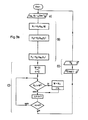
- FIG. 2 shows, over time t, three, for example, given courses of the phase angle differences d 1 to d 3 for correspondingly different, predetermined values of the equivalent reactance X e1 to X e3 .
- these values are selected based on plausibility considerations, taking into account the known rough network conditions, so that the actual reactance value lies in the range of variation of the specified values.
- the similarity test of the course, in each case over a time interval T can, for example, as illustrated in FIG. 2, by forming a difference between d m and d 1 to d 3 (see the hatched difference areas) with correlating the difference value with one of the difference-forming variables, for example d m , be performed. In this case there is an inverse similarity criterion with a corresponding minimum value selection.
- the correlation itself can be carried out in the usual way by multiplication - in the example, the difference value - with one of the difference-forming quantities and integration over the interval T.
- each a set of metrics d m, P, Q, V 1 is housed in process step a) following the procedure start and subsequently in process step b) the size d m in a memory Sp outputted.
- the variable d 1 of the phase angle difference is determined in method step c) and output in the memory Sp in the subsequent step d).
- the method continues in this way with the introduction of the other specified reactance values up to X e3 with formation and output of the last value of the phase angle difference, for example d 3 .
- a new cycle cycle follows, starting with the recording of a new set of the measured variables d m , P, Q, V 1 .
- a memory which is cyclically renewed step by step a so-called “rotating” memory, in which the courses of the variables d m and d 1 to d 3 are stored over a time interval T.
- the renewal is carried out in the usual way by overwriting the longest stored value set by the last recorded one. Suitable history sections are therefore always available in the memory for the similarity check.
- the process can then continue cyclically, so that there is constant network identification for regulatory and management purposes.
Landscapes
- Physics & Mathematics (AREA)
- General Physics & Mathematics (AREA)
- Measurement Of Resistance Or Impedance (AREA)
Claims (7)
Applications Claiming Priority (2)
| Application Number | Priority Date | Filing Date | Title |
|---|---|---|---|
| CH273579 | 1979-03-23 | ||
| CH2735/79 | 1979-03-23 |
Publications (2)
| Publication Number | Publication Date |
|---|---|
| EP0017676A1 EP0017676A1 (fr) | 1980-10-29 |
| EP0017676B1 true EP0017676B1 (fr) | 1983-01-26 |
Family
ID=4240423
Family Applications (1)
| Application Number | Title | Priority Date | Filing Date |
|---|---|---|---|
| EP79200189A Expired EP0017676B1 (fr) | 1979-03-23 | 1979-04-17 | Procédé pour la détermination d'une réactance virtuelle longitudinale dans un réseau électrique |
Country Status (5)
| Country | Link |
|---|---|
| US (1) | US4307336A (fr) |
| EP (1) | EP0017676B1 (fr) |
| BR (1) | BR8001720A (fr) |
| CA (1) | CA1143007A (fr) |
| DE (1) | DE2964591D1 (fr) |
Families Citing this family (3)
| Publication number | Priority date | Publication date | Assignee | Title |
|---|---|---|---|---|
| US4612498A (en) * | 1982-08-06 | 1986-09-16 | Smalley Daniel S | Induction furnace fault locator |
| US4525665A (en) * | 1982-08-06 | 1985-06-25 | Smalley Daniel S | Induction furnace monitor |
| US5300876A (en) † | 1990-05-11 | 1994-04-05 | Kabushiki Kaisha Toshiba | Power system stabilizer estimating a power system impedance |
Family Cites Families (8)
| Publication number | Priority date | Publication date | Assignee | Title |
|---|---|---|---|---|
| US2592750A (en) * | 1946-05-03 | 1952-04-15 | Us Navy | Impedance meter |
| US2595297A (en) * | 1947-06-26 | 1952-05-06 | Matthew J Relis | Method and apparatus for measuring electrical impedances |
| US2593175A (en) * | 1947-07-08 | 1952-04-15 | Technology Instr Corp | Electric method and system for measuring impedance magnitude and phase angle |
| GB998337A (en) * | 1963-02-26 | 1965-07-14 | Secr Aviation | Improvements in or relating to phase measuring circuits |
| US3445763A (en) * | 1965-10-06 | 1969-05-20 | Gen Electric | Digital reading impedance measuring arrangement |
| US3526761A (en) * | 1969-05-15 | 1970-09-01 | Otto J M Smith | Method,apparatus and system for the identification of the relationship between two signals |
| DE2213995B2 (de) * | 1972-03-22 | 1977-08-25 | Frequenzselektive, insbesondere fuer den wobbelbetrieb geeignete messchaltung | |
| DE2247746C3 (de) * | 1972-09-29 | 1975-11-27 | Siemens Ag, 1000 Berlin Und 8000 Muenchen | Verfahren zum Messen einer Leitungsimpedanz |
-
1979
- 1979-04-17 EP EP79200189A patent/EP0017676B1/fr not_active Expired
- 1979-04-17 DE DE7979200189T patent/DE2964591D1/de not_active Expired
-
1980
- 1980-03-12 CA CA000347542A patent/CA1143007A/fr not_active Expired
- 1980-03-19 US US06/131,662 patent/US4307336A/en not_active Expired - Lifetime
- 1980-03-21 BR BR8001720A patent/BR8001720A/pt not_active IP Right Cessation
Also Published As
| Publication number | Publication date |
|---|---|
| BR8001720A (pt) | 1981-09-22 |
| DE2964591D1 (en) | 1983-03-03 |
| CA1143007A (fr) | 1983-03-15 |
| US4307336A (en) | 1981-12-22 |
| EP0017676A1 (fr) | 1980-10-29 |
Similar Documents
| Publication | Publication Date | Title |
|---|---|---|
| DE69120880T2 (de) | Abtastende Messeinrichtung | |
| DE2812121A1 (de) | Messeinrichtung zur messung von wechselstromgroessen unter verwendung digitaler datenverarbeitung | |
| DE3005672A1 (de) | Verfahren zum messen eines parameters | |
| DE1124739B (de) | Recheneinrichtung | |
| DE3124333A1 (de) | "digital/analog-umsetzer" | |
| DE2152687B2 (de) | Verfahren und Einrichtung zum Erkennen einer vorbestimmten Frequenz in einem Frequenzgemisch | |
| CH648934A5 (de) | Verfahren zur messung elektrischer leistung. | |
| DE1591872A1 (de) | Schaltungsanordnung zur Feststellung des Synchronismus zwischen zwei Frequenzen | |
| DE1474101A1 (de) | Vielkanal-Korrelationsrechner | |
| DE69614331T2 (de) | Signalangepasstes Filter | |
| CH683721A5 (de) | Verfahren zur Ermittlung von Schätzwerten der Momentanwerte von Parametern mindestens eines sinusförmigen Signals mit konstanter und vorbekannter Frequenz. | |
| DE2355640A1 (de) | Anordnung zur spektralanalyse von elektrischen signalen | |
| DE2812325A1 (de) | Elektronisches zuendsteuersystem | |
| EP0017676B1 (fr) | Procédé pour la détermination d'une réactance virtuelle longitudinale dans un réseau électrique | |
| DE4121637C2 (de) | Verfahren zur Prüfung von Steuergeräten und Prüfeinrichtung zur Durchführung des Verfahrens | |
| DE2704141C2 (fr) | ||
| DE2801520A1 (de) | Messeinrichtung zur bestimmung der periodendauer einer wechselspannung | |
| DE2950031A1 (de) | Ueberwachungsgeraet | |
| EP0207881B1 (fr) | Méthode de génération d'un signal de déclenchement en dépendance de l'intensité et de la durée d'un surcourant | |
| DE2453873A1 (de) | Fourier-analysator | |
| EP3521949A1 (fr) | Dispositif de simulation d'une machine ou d'une installation commandées ainsi que procédé | |
| DE3105554A1 (de) | Schaltungsanordnung zur erzeugung von abtastimpulsen | |
| DE2309054A1 (de) | Verfahren und vorrichtung zum bestimmen des wertes einer fuer zwei reelle zeitfunktionen definierten zweideutigkeitsfunktion | |
| DE3043727A1 (de) | Verfahren zum periodischen wandeln eines digitalwertes in einen analogwert | |
| DE2028731C3 (de) | Schaltungsanordnung zur meßtechnischen Bestimmung zeitlicher Mittelwerte |
Legal Events
| Date | Code | Title | Description |
|---|---|---|---|
| PUAI | Public reference made under article 153(3) epc to a published international application that has entered the european phase |
Free format text: ORIGINAL CODE: 0009012 |
|
| AK | Designated contracting states |
Designated state(s): CH DE FR |
|
| 17P | Request for examination filed |
Effective date: 19801031 |
|
| RAP1 | Party data changed (applicant data changed or rights of an application transferred) |
Owner name: BBC AKTIENGESELLSCHAFT BROWN, BOVERI & CIE. |
|
| GRAA | (expected) grant |
Free format text: ORIGINAL CODE: 0009210 |
|
| AK | Designated contracting states |
Designated state(s): CH DE FR |
|
| REF | Corresponds to: |
Ref document number: 2964591 Country of ref document: DE Date of ref document: 19830303 |
|
| ET | Fr: translation filed | ||
| PGFP | Annual fee paid to national office [announced via postgrant information from national office to epo] |
Ref country code: FR Payment date: 19980313 Year of fee payment: 20 |
|
| PGFP | Annual fee paid to national office [announced via postgrant information from national office to epo] |
Ref country code: DE Payment date: 19980318 Year of fee payment: 20 |
|
| PGFP | Annual fee paid to national office [announced via postgrant information from national office to epo] |
Ref country code: CH Payment date: 19980325 Year of fee payment: 20 |
|
| PG25 | Lapsed in a contracting state [announced via postgrant information from national office to epo] |
Ref country code: CH Free format text: LAPSE BECAUSE OF EXPIRATION OF PROTECTION Effective date: 19990416 |
|
| REG | Reference to a national code |
Ref country code: CH Ref legal event code: PL |
|
| PLBE | No opposition filed within time limit |
Free format text: ORIGINAL CODE: 0009261 |
|
| STAA | Information on the status of an ep patent application or granted ep patent |
Free format text: STATUS: NO OPPOSITION FILED WITHIN TIME LIMIT |