EP0017732A1 - Bodenschwelle, insbesondere für ein Fenster oder eine Tür - Google Patents
Bodenschwelle, insbesondere für ein Fenster oder eine Tür Download PDFInfo
- Publication number
- EP0017732A1 EP0017732A1 EP19800100914 EP80100914A EP0017732A1 EP 0017732 A1 EP0017732 A1 EP 0017732A1 EP 19800100914 EP19800100914 EP 19800100914 EP 80100914 A EP80100914 A EP 80100914A EP 0017732 A1 EP0017732 A1 EP 0017732A1
- Authority
- EP
- European Patent Office
- Prior art keywords
- extension
- weather board
- threshold
- weather
- drip
- Prior art date
- Legal status (The legal status is an assumption and is not a legal conclusion. Google has not performed a legal analysis and makes no representation as to the accuracy of the status listed.)
- Granted
Links
- 238000004519 manufacturing process Methods 0.000 claims description 4
- 238000007789 sealing Methods 0.000 claims description 4
- XAGFODPZIPBFFR-UHFFFAOYSA-N aluminium Chemical compound [Al] XAGFODPZIPBFFR-UHFFFAOYSA-N 0.000 description 2
- 229910052782 aluminium Inorganic materials 0.000 description 2
- 238000010276 construction Methods 0.000 description 2
- 241001669679 Eleotris Species 0.000 description 1
- 230000015572 biosynthetic process Effects 0.000 description 1
- 238000009833 condensation Methods 0.000 description 1
- 230000005494 condensation Effects 0.000 description 1
- 238000001125 extrusion Methods 0.000 description 1
- 230000002349 favourable effect Effects 0.000 description 1
- 239000007788 liquid Substances 0.000 description 1
- 239000000463 material Substances 0.000 description 1
- 238000000034 method Methods 0.000 description 1
- 238000003825 pressing Methods 0.000 description 1
- 239000003351 stiffener Substances 0.000 description 1
Images
Classifications
-
- E—FIXED CONSTRUCTIONS
- E06—DOORS, WINDOWS, SHUTTERS, OR ROLLER BLINDS IN GENERAL; LADDERS
- E06B—FIXED OR MOVABLE CLOSURES FOR OPENINGS IN BUILDINGS, VEHICLES, FENCES OR LIKE ENCLOSURES IN GENERAL, e.g. DOORS, WINDOWS, BLINDS, GATES
- E06B1/00—Border constructions of openings in walls, floors, or ceilings; Frames to be rigidly mounted in such openings
- E06B1/70—Sills; Thresholds
-
- E—FIXED CONSTRUCTIONS
- E06—DOORS, WINDOWS, SHUTTERS, OR ROLLER BLINDS IN GENERAL; LADDERS
- E06B—FIXED OR MOVABLE CLOSURES FOR OPENINGS IN BUILDINGS, VEHICLES, FENCES OR LIKE ENCLOSURES IN GENERAL, e.g. DOORS, WINDOWS, BLINDS, GATES
- E06B3/00—Window sashes, door leaves, or like elements for closing wall or like openings; Layout of fixed or moving closures, e.g. windows in wall or like openings; Features of rigidly-mounted outer frames relating to the mounting of wing frames
- E06B3/32—Arrangements of wings characterised by the manner of movement; Arrangements of movable wings in openings; Features of wings or frames relating solely to the manner of movement of the wing
- E06B3/34—Arrangements of wings characterised by the manner of movement; Arrangements of movable wings in openings; Features of wings or frames relating solely to the manner of movement of the wing with only one kind of movement
- E06B3/42—Sliding wings; Details of frames with respect to guiding
- E06B3/46—Horizontally-sliding wings
- E06B3/4609—Horizontally-sliding wings for windows
-
- E—FIXED CONSTRUCTIONS
- E06—DOORS, WINDOWS, SHUTTERS, OR ROLLER BLINDS IN GENERAL; LADDERS
- E06B—FIXED OR MOVABLE CLOSURES FOR OPENINGS IN BUILDINGS, VEHICLES, FENCES OR LIKE ENCLOSURES IN GENERAL, e.g. DOORS, WINDOWS, BLINDS, GATES
- E06B1/00—Border constructions of openings in walls, floors, or ceilings; Frames to be rigidly mounted in such openings
- E06B1/70—Sills; Thresholds
- E06B2001/707—Thresholds with special provision for insulation
Definitions
- the invention relates to a threshold, in particular for a window or a door with a weatherboard.
- the structural conditions require weather bars of different widths. This applies in particular if a roller shutter or the like is provided on the window or door, which is to stand on the threshold.
- thresholds with weather bars of different widths were alternatively offered. From an economic point of view, however, this is impractical and, if nothing else, leads to an increase in price, because smaller series are needed for the individual sizes than would be the case if only one size was produced.
- the object of the invention is therefore to create a threshold, in particular for a window or a door with a weatherboard, which meets the most varied requirements with regard to the width of the weatherboard.
- a threshold in particular for a window or a door, is equipped with a weatherstrip according to the invention with an attached weatherstrip extension.
- the latter is a comparatively simple and therefore easy and cheap to manufacture component.
- the threshold is subjected to a more or less wide weather leg extension attached.
- the threshold itself can be manufactured in comparatively large numbers and therefore inexpensively. Seen overall, the solution according to the invention is therefore more economical than the previously used one.
- a further development of the invention provides that the weather bar extension is pushed onto the drip nose, latched or snapped in place, or is fastened in a similar manner without screws. This not only saves fasteners, but also their relatively time-consuming assembly. There is also the fact that a screwless, or more generally speaking, attachment of the weatherstrip extension to the threshold which does without fastening elements also gives a more favorable appearance.
- a preferred embodiment of the invention is characterized in that in order to form a fastening groove of approximately U-shaped cross section, a retaining web is attached to the drip nose, in particular molded on, by a counter web or a shoulder of the weather bar extension is engaged, and that the weather bar extension is supported on the outer surface of the drip nose. Because of this external support, a secure interlocking of the retaining web and counter-web is guaranteed.
- the connection can be made, for example, by sliding the weatherstrip extension in the longitudinal direction onto the drip nose of the threshold.
- Another fastening of the weatherstrip extension is possible if, according to a further embodiment of the invention, into a gap between the outer surface of the drip nose and the preferably approximately parallel surface of a strip of an especially U-shaped fastening rail of the weatherstrip extension an essentially strip-shaped intermediate member is inserted.
- the retaining web of the threshold and the counterpart of the weatherstrip extension are dimensioned and arranged in such a way that the weatherstrip extension can be plugged onto the drip nose, so to speak, from below. Subsequently, one then hooks the retaining web and the counter web, so that the gap space for inserting the intermediate link arises.
- the latter is elastic enough on the one hand to be able to be pressed into the gap space, but on the other hand so stiff that the hooking of the retaining web and counter-web is permanently ensured by its pressure force exerted on the gap side walls. It is particularly advantageous if the intermediate member is a press-in or roll-in sealing profile. On the one hand it ensures that no liquid, but also no dirt can enter the gap between the threshold and the weatherstrip extension, and on the other hand it is able to exert the necessary pretensioning force on the hooked connection of the threshold and the weatherstrip extension.
- An advantageous further development of the invention consists in that a fastening leg which engages under the weather leg extension is connected to the fastening rail of the weather leg extension and transmits the loads which are exerted on the weather leg extension from below to the threshold and ensures a stiffening in this area.
- the weatherstrip extension advantageously has a drip nose.
- Another embodiment of the invention is characterized by a one-piece production of the threshold, in particular as an extruded profile with a running rail. This eliminates the separate manufacture and fastening of the running rail to the threshold.
- the threshold can be designed in two parts to form a so-called isolated construction.
- the part of the threshold that faces the interior of the room consists of a material of lower conductivity than the rest of the, usually much larger, part of the threshold, which, like the exemplary embodiment, consists of an aluminum profile. This prevents both the formation of condensation inside the room and the creation of a cold bridge to the outside.
- the running rail is expediently manufactured separately and mounted on the floor sleeper part, for example made of plastic, with lower thermal conductivity.
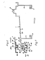
- the threshold 1 is preferably made in one piece with a running rail 2 and can be produced in particular from aluminum using the extrusion process. If one disregards the running rail 2, the threshold is an essentially U-shaped profile with a cover plate 3 and the two side webs 4 and 5. At the free ends of the latter there is a latching receptacle 6 and 7, respectively The latter serve to receive a strip-shaped latching element of one or more stiffeners, which are arranged in an extension of one another and connect the free ends of the side webs 4 and 5, for example.
- the cover plate 3 runs slightly outwards in the installed position and with vertical side webs 4 and 5 inclined. It is extended to the outside by a weather bar 8.
- a weather bar 8 On the free longitudinal edge of the weather bar 8, a strip-shaped drip nose 9 extending downward is formed. At its free end there is a holding web 10. The latter, the drip nose 9 and the outer longitudinal edge of the weather leg 8 together form a fastening groove 11, which is preferably approximately U-shaped in cross section, for a weather leg extension 12.
- the retaining web 10 is gripped by a shoulder or a counter web 13 of the weather bar extension in the final assembly position.
- This counter web projects into the interior of a fastening rail 14 of the weatherstrip extension 12 which is approximately U-shaped in cross section in the final assembly position exactly in the extension of the weather bar 8 or the cover plate 3 of the threshold 1.
- a downwardly projecting drip nose 16 is attached to the free end of the weather bar extension 12.
- At right angles to the side web 15 of the fastening Rail 14 extends a particularly angular support leg 17. In the final assembly position (Fig. 2), it engages under the weather leg 8th
- the weatherstrip extension 12 with the above-mentioned parts made in one piece with it is pushed in the direction of arrow 18 from below onto the drip nose 9 of the threshold 1.
- the weather leg extension 12 is displaced with respect to the threshold 1 in the direction of arrow 21 until the retaining web 10 and the counter web 13 are hooked together in the manner shown in FIG. 2 are.
- the drip nose 9 and the leg 22 of the fastening rail 14 then form a gap 23 which is delimited at the bottom by the transverse web 24 of the fastening rail 14.
- a strip-shaped intermediate member 26 is inserted or pressed into this gap space 23 from above in the direction of arrow 25.
- the weatherboard extension 12 in the exemplary embodiment is supported indirectly via the intermediate member 26 on the outer surface 31 of the drip nose 9.
Landscapes
- Engineering & Computer Science (AREA)
- Civil Engineering (AREA)
- Structural Engineering (AREA)
- Seal Device For Vehicle (AREA)
Abstract
Description
- Die Erfindung bezieht sich auf eine Bodenschwelle, insbesondere für ein Fenster oder eine Tür mit einem Wetterschenkel. Die baulichen Verhältnisse verlangen unterschiedlich breite Wetterschenkel. Dies gilt insbesondere dann, wenn an dem Fenster oder der Tür ein Rolladen od. dgl. vorgesehen ist, der auf der Bodenschwelle aufstehen soll. Um den Kundenwünschen entsprechen zu können, wurden infolgedessen Bodenschwellen mit verschieden breiten Wetterschenkeln alternativ angeboten. Aus wirtschaftlicher Sicht ist das allerdings unzweckmäßig und führt schon deswegen zu einer Verteuerung, weil für die einzelnen Größen kleinere Serien gebraucht werden, als dies bei Herstellung lediglich einer einzigen Größe der Fall wäre.
- Die Aufgabe der Erfindung besteht infolgedessen darin, eine Bodenschwelle, insbesondere für ein Fenster oder eine Tür mit einem Wetterschenkel zu schaffen, die den verschiedensten Anforderungen hinsichtlich der Wetterschenkelbreite gerecht wird.
- Zur Lösung dieser Aufgabe wird eine Bodenschwelle, insbesondere für ein Fenster oder eine Tür mit einem Wetterschenkel erfindungsgemäß mit einer angesetzten Wetterschenkelverlängerung ausgestattet. Letztere ist ein vergleichsweise einfaches und damit leicht und billig herzustellendes Bauteil. Um nun die Gesamtbreite der Bodenschwelle variieren und den jeweiligen Bedürfnissen somit anpassen zu können, wird an die Bodenschwelle eine mehr oder weniger breite Wetterschenkelverlängerung angesetzt. Die Bodenschwelle selbst kann in vergleichsweise großen Stückzahlen und damit preisgünstig hergestellt werden. Insgesamt gesehen, ist die erfindungsgemäße Lösung somit wirtschaftlicher als die bislang gebräuchliche.
- Bei einer Bodenschwelle mit einer Abtropfnase am freien Ende des Wetterschenkels sieht eine Weiterbildung der Erfindung vor, daß die Wetterschenkelverlängerung auf die Abtropfnase aufgeschoben, rastend oder schnappend angehängt oder in ähnlicher Weise schraubenlos befestigt ist. Das erspart nicht nur Befestigungselemente, sondern auch deren relativ zeitaufwendige Montage. Es kommt noch hinzu, daß eine schraubenlose, oder allgemeiner gesprochen, auf Befestigungselemente verzichtende Anbringung der Wetterschenkelverlängerung an der Bodenschwelle auch optisch ein günstigeres Aussehen ergibt.
- Eine bevorzugte Ausführungsform der Erfindung ist dadurch gekennzeichnet, daß zur Bildung einer im Querschnitt etwa U-förmigen Befestigungsnut an die Abtropfnase ein Haltesteg angesetzt, insbesondere angeformt ist, der von einem Gegensteg oder einer Schulter der Wetterschenkelverlängerung hintergriffen ist, und daß die Wetterschenkelverlängerung zugleich an der Außenfläche der Abtropfnase abgestützt ist. Aufgrund dieser äußeren Abstützung ist eine sichere Verhakung von Haltesteg und Gegensteg gewährleistet. Die Verbindung kann beispielsweise dadurch erfolgen, daß man die Wetterschenkelverlängerung in Längsrichtung auf die Abtropfnase der Bodenschwelle aufschiebt.
- Eine andere, mit einem Aufsteckvorgang vergleichbare Befestigung der Wetterschenkelverlängerung, ist dann möglich, wenn gemäß einer weiteren Ausgestaltung der Erfindung in einen Spaltraum zwischen der Außenfläche der Abtropfnase und der dazu vorzugsweise etwa parallelen Fläche einer Leiste einer insbesondere im Querschnitt etwa U-förmigen Befestigungsschiene der Wetterschenkelverlängerung ein im wesentlichen streifenförmiges Zwischenglied eingeschoben wird. Dabei sind der Haltesteg der Bodenschwelle und der Gegensteg der Wetterschenkelverlängerung so dimensioniert und angeordnet, daß man die Wetterschenkelverlängerung gewissermaßen von unten her auf die Abtropfnase aufstecken kann. Nachfolgend verhakt man dann den Haltesteg und den Gegensteg, so daß der Spaltraum zum Einstecken des Zwischenglieds entsteht. Letzteres ist einerseits elastisch genug, um in den Spaltraum eingepreßt werden zu können, andererseits aber so steif, daß durch seine auf die Spaltseitenwände ausgeübte Druckkraft die Verhakung von Haltesteg und Gegensteg dauerhaft gewährleistet ist. Dabei ist es von besonderem Vorteil, wenn das Zwischenglied ein einpreß- oder einwalzbares Dichtprofil ist. Es sorgt einerseits dafür, daß keine Flüssigkeit, aber auch kein Schmutz in den Spaltraum zwischen Bodenschwelle und Wetterschenkelverlängerung eintreten kann, und andererseits ist es in der Lage, die erforderliche Vorspannkraft auf die verhakende Verbindung von Bodenschwelle und Wetterschenkelverlängerung auszuüben.
- Eine vorteilhafte Weiterbildung der Erfindung besteht darin, daß sich an die Befestigungsschiene der Wetterschenkelverlängerung ein den Wetterschenkel untergreifender Stützschenkel anschließt, der auf die Wetterschenkelverlängerung aufgegebene Belastungen von unten her an die Bodenschwelle überträgt und für eine Versteifung in diesem Bereich sorgt.
- Die Wetterschenkelverlängerung weist vorteilhafterweise eine Abtropfnase auf. Eine andere Ausbildung der Erfindung ist gekennzeichnet durch eine einstückige Fertigung der Bodenschwelle insbesondere als Strangpreßprofil mit einer Laufschiene. Dadurch entfällt die separate Herstellung und Befestigung der Laufschiene an der Bodenschwelle. Andererseits kann aber die Bodenschwelle durchaus zweiteilig ausgebildet sein, um eine sogenannte isolierte Konstruktion zu bilden. Dabei besteht der dem Rauminnern zugekehrte Teil der Bodenschwelle aus einem Werkstoff geringerer Leitfähigkeit als der übrige, in der Regel weit größere Teil der Bodenschwelle, die ebenso wie das Ausführungsbeispiel aus einem Aluminiumprofil besteht. Hierdurch läßt sich sowohl die Schwitzwasserbildung im Rauminnern als auch die Schaffung einer Kältebrücke nach außen verhindern. Im Falle einer Isolierkonstruktion wird die Laufschiene zweckmäßigerweise separat gefertigt und auf den beispielsweise aus Kunststoff bestehenden Bodenschwellenteil mit geringerer Wärmeleitfähigkeit aufmontiert.
- In der Zeichnung ist ein Ausführungsbeispiel der Erfindung dargestellt.
- Es zeigen:
- Figur 1 eine explosionsartige Darstellung der Bodenschwelle mit der Wetterschenkelverlängerung und dem Zwischenglied,
- Figur 2 eine abgebrochene Darstellung der zusammengebauten Teile der Fig. 1.
- Die Bodenschwelle 1 ist vorzugsweise einstückig mit einer Laufschiene 2 gefertigt und kann insbesondere im Strangpreßverfahren aus Aluminium hergestellt werden. Wenn man von der Laufschiene 2 absieht, so handelt es sich bei der Bodenschwelle um ein im wesentlichen U-förmiges Profil mit einer Deckplatte 3 und den beiden Seitenstegen 4 und 5. An den freien Enden der letzteren befindet sich je eine Verrastaufnahme 6 bzw. 7. Letztere dienen zur Aufnahme je eines leistenförmigen Verrastelements einer oder mehrerer in Verlängerung voneinander angeordneter, die freien Enden der Seitenstege 4 und 5 verbindender, beispielsweise plattenförmiger Versteifung.
- Die Deckplatte 3 verläuft in der Einbaulage und bei senkrecht stehenden Seitenstegen 4 und 5 nach außen hin leicht geneigt. Sie wird durch einen Wetterschenkel 8 nach außen hin verlängert. Am freien Längsrand des Wetterschenkels 8 ist eine leistenförmige, sich nach unten hin erstreckende Abtropfnase 9 angefornt. An deren freiem Ende befindet sich ein Haltesteg 10. Letzterer, die Abtropfnase 9 und der äußere Längsrand des Wetterschenkels 8 bilden zusammen eine im Querschnitt vorzugsweise etwa U-förmige Befestigungsnut 11 für eine Wetterschenkelverlängerung 12.
- Der Haltesteg 10 wird von einer Schulter oder einem Gegensteg 13 der Wetterschenkelverlängerung in der Montageendlage hintergriffen. Dieser Gegensteg ragt ins Innere einer im Querschnitt etwa U-förmigen Befestigungsschiene 14 der Wetterschenkelverlängerung 12. Er ist an den Seitensteg 15 der Befestigungsschiene 14 angeformt und erstreckt sich im wesentlichen etwa parallel zur Wetterschenkelverlängerung 12. Letztere ist im übrigen von plattenförmiger Gestalt, und sie verläuft in der Montageendlage genau in Verlängerung vom Wetterschenkel 8 bzw. der Deckplatte 3 der Bodenschwelle 1. An das freie Ende der Wetterschenkelverlängerung 12 ist eine nach unten ragende Abtropfnase 16 angesetzt. Rechtwinklig zum Seitensteg 15 der Befestigungsschiene 14 erstreckt sich ein insbesondere winkelförmiger Stützschenkel 17. In der Montageendlage (Fig. 2) untergreift er den Wetterschenkel 8.
- Die Wetterschenkelverlängerung 12 mit den damit einstückig hergestellten, vorstehend erwähnten Teilen, wird in Richtung des Pfeils 18 von unten her auf die Abstropfnase 9 der Bodenschwelle 1 aufgesteckt. Wenn das verdickte Ende 19 des Stützschenkels 17 an der unteren Fläche 20 des Wetterschenkels 8 aufgetroffen ist, verschiebt man die Wetterschenkelverlängerung 12 gegenüber der Bodenschwelle 1 in Pfeilrichtung 21, bis der Haltesteg 10 und der Gegensteg 13 in der aus Fig. 2 ersichtlichen Weise miteinander verhakt sind. Dabei bilden dann die Abtropfnase 9 und der Schenkel 22 der Befestigungsschiene 14 einen Spaltraum 23, der nach unten hin durch den Quersteg 24 der Befestigungsschiene 14 begrenzt ist. In diesen Spaltraum 23 wird von oben her im Sinne des Pfeils 25 ein streifenförmiges Zwischenglied'26 eingeschoben oder eingepreßt. Es besteht beim Ausführungsbeispiel aus einer an ihrem oberen Ende 27 verdickten Leiste 28. In gleicher Richtung wie das verdickte Ende erstrecken sich noch zwei im Abstand übereinander angeordnete Dichtlippen 29 und 30. Das Dichtprofil kann beispielsweise aus Kunststoff hergestellt werden, und es schließt den Spaltraum 23 oben bündig mit den nach oben weisenden Flächen 33 und 32 der Bodenschwelle 1 bzw. der Wetterschenkelverlängerung 12 ab. Durch das Einpressen des Zwischenglieds 26 entsteht eine Druckkraft auf die Innenwandungen des Seitenstegs 15 und des Schenkels 22 der Befestigungsschiene 14, welche den Gegensteg 13 gegen die Innenfläche der Abtropfnase 9 drückt und so die Verhakung des Haltestegs 10 und des Gegenstegs 13 sichert. Damit ist die Wetterschenkelverlängerung 12 beim Ausführungsbeispiel indirekt über das Zwischenglied 26 an der Außenfläche 31 der Abtropfnase 9 abgestützt.
Claims (8)
Applications Claiming Priority (2)
| Application Number | Priority Date | Filing Date | Title |
|---|---|---|---|
| DE7908717U | 1979-03-28 | ||
| DE19797908717 DE7908717U1 (de) | 1979-03-28 | 1979-03-28 | Bodenschwelle, insbesondere fuer ein fenster oder eine tuer |
Publications (3)
| Publication Number | Publication Date |
|---|---|
| EP0017732A1 true EP0017732A1 (de) | 1980-10-29 |
| EP0017732B1 EP0017732B1 (de) | 1983-05-11 |
| EP0017732B2 EP0017732B2 (de) | 1985-08-28 |
Family
ID=6702472
Family Applications (1)
| Application Number | Title | Priority Date | Filing Date |
|---|---|---|---|
| EP19800100914 Expired EP0017732B2 (de) | 1979-03-28 | 1980-02-25 | Bodenschwelle, insbesondere für ein Fenster oder eine Tür |
Country Status (3)
| Country | Link |
|---|---|
| EP (1) | EP0017732B2 (de) |
| AT (1) | AT380308B (de) |
| DE (1) | DE7908717U1 (de) |
Cited By (3)
| Publication number | Priority date | Publication date | Assignee | Title |
|---|---|---|---|---|
| EP2228511A3 (de) * | 2009-03-12 | 2013-12-18 | Veka AG | Mehrteiliges Schwellenprofil für eine Hebeschiebetür |
| EP2202378A3 (de) * | 2008-12-29 | 2014-03-19 | HAUTAU GmbH | Nachtraeglich montierbare Bodenschwelle für ein Hebeschiebfenster und Montageverfahren |
| US11174673B2 (en) | 2019-05-24 | 2021-11-16 | Nana Wall Systems, Inc. | Threshold sill with removable barrier insert |
Families Citing this family (2)
| Publication number | Priority date | Publication date | Assignee | Title |
|---|---|---|---|---|
| DE7908717U1 (de) * | 1979-03-28 | 1979-06-28 | Gretsch-Unitas Gmbh Baubeschlagfabrik, 7257 Ditzingen | Bodenschwelle, insbesondere fuer ein fenster oder eine tuer |
| DE19654992C2 (de) * | 1996-01-31 | 1999-02-04 | Peter Willrich | Unterer Abschluß von Türen oder Fenstern |
Citations (4)
| Publication number | Priority date | Publication date | Assignee | Title |
|---|---|---|---|---|
| US2826282A (en) * | 1955-06-24 | 1958-03-11 | Goldberg Ralph | Horizontal sliding window structure and frame therefor |
| DE6909549U (de) * | 1969-03-03 | 1969-10-23 | Ziegler Metallbau Kg | Metall-fensterbank |
| CH555467A (de) * | 1973-10-09 | 1974-10-31 | Ind Bauelemente Ag | Leichtmetall-wetterschenkel fuer holzfenster und glastueren. |
| DE7908717U1 (de) * | 1979-03-28 | 1979-06-28 | Gretsch-Unitas Gmbh Baubeschlagfabrik, 7257 Ditzingen | Bodenschwelle, insbesondere fuer ein fenster oder eine tuer |
-
1979
- 1979-03-28 DE DE19797908717 patent/DE7908717U1/de not_active Expired
-
1980
- 1980-02-25 EP EP19800100914 patent/EP0017732B2/de not_active Expired
- 1980-03-04 AT AT117980A patent/AT380308B/de not_active IP Right Cessation
Patent Citations (4)
| Publication number | Priority date | Publication date | Assignee | Title |
|---|---|---|---|---|
| US2826282A (en) * | 1955-06-24 | 1958-03-11 | Goldberg Ralph | Horizontal sliding window structure and frame therefor |
| DE6909549U (de) * | 1969-03-03 | 1969-10-23 | Ziegler Metallbau Kg | Metall-fensterbank |
| CH555467A (de) * | 1973-10-09 | 1974-10-31 | Ind Bauelemente Ag | Leichtmetall-wetterschenkel fuer holzfenster und glastueren. |
| DE7908717U1 (de) * | 1979-03-28 | 1979-06-28 | Gretsch-Unitas Gmbh Baubeschlagfabrik, 7257 Ditzingen | Bodenschwelle, insbesondere fuer ein fenster oder eine tuer |
Cited By (4)
| Publication number | Priority date | Publication date | Assignee | Title |
|---|---|---|---|---|
| EP2202378A3 (de) * | 2008-12-29 | 2014-03-19 | HAUTAU GmbH | Nachtraeglich montierbare Bodenschwelle für ein Hebeschiebfenster und Montageverfahren |
| EP2228511A3 (de) * | 2009-03-12 | 2013-12-18 | Veka AG | Mehrteiliges Schwellenprofil für eine Hebeschiebetür |
| US11174673B2 (en) | 2019-05-24 | 2021-11-16 | Nana Wall Systems, Inc. | Threshold sill with removable barrier insert |
| US12110733B2 (en) | 2019-05-24 | 2024-10-08 | Nana Wall Systems, Inc. | Threshold sill with removable barrier insert |
Also Published As
| Publication number | Publication date |
|---|---|
| ATA117980A (de) | 1985-09-15 |
| AT380308B (de) | 1986-05-12 |
| EP0017732B2 (de) | 1985-08-28 |
| EP0017732B1 (de) | 1983-05-11 |
| DE7908717U1 (de) | 1979-06-28 |
Similar Documents
| Publication | Publication Date | Title |
|---|---|---|
| EP0009652B1 (de) | Bausatz für vertikale oder horizontale Schiebefenster | |
| DE1123523B (de) | Befestigungselement aus elastisch nachgiebigem Kunststoff zum Befestigen von rinnenfoermigen Leisten, z.B. Zierleisten, auf einer gelochten Wand, z.B. einer Karosseriewand | |
| DE1916630B1 (de) | Bettrahmenteil | |
| DE9016725U1 (de) | Abdeckung für einen Flügelrahmen eines Dachfensters | |
| DE4216260C2 (de) | Gebäudefenster | |
| DE9407415U1 (de) | Abschlußelement für Wandöffnungen in Gebäuden od.dgl. | |
| EP0003042A1 (de) | Rahmenprofil für einen Schiebeflügel | |
| EP1243738A2 (de) | Holz-Alu-Fenster | |
| EP0017732B1 (de) | Bodenschwelle, insbesondere für ein Fenster oder eine Tür | |
| DE2443098A1 (de) | Anordnung zur befestigung eines verkleidungsprofiles | |
| DE7908753U1 (de) | Rahmenprofil fuer ein fenster, eine tuer o.dgl. | |
| EP0016957A1 (de) | Bodenschwelle mit Laufschiene | |
| DE3201833C2 (de) | Eckwinkel aus Stanzblech zur Verbindung von Abstandhalter-Hohlprofilen für Isolierverglasungen | |
| DE2514694B2 (de) | Hölzerner Blendrahmen für Fenster oder Türen mit einem Abdeckprofil aus wetterfestem Material | |
| DE60000092T2 (de) | Treibstangenverschluss für Rahmen von Türen oder Fenstern | |
| AT396385B (de) | Stockrahmenprofil | |
| DE2805258A1 (de) | Vorrichtung zur halterung einer abdeckplatte an einer schiene | |
| DE2338199C2 (de) | Fensterrahmen eines Modernisierungsfensters mit Befestigungseinrichtung für den in der Wand verbleibenden Stockrahmen des alten Fensters | |
| CH663058A5 (de) | Aluminium-fensterbank. | |
| EP0658676B1 (de) | Verglasungssystem für Aussenwände von Gebäuden | |
| AT256414B (de) | Rahmenkonstruktion für Schiebefenster, Schiebetüren u. dgl. | |
| DE7437783U (de) | Vorrichtung zur Verstärkung von Kunststoffprofilen | |
| EP0886028A2 (de) | Halteprofil | |
| DE7308774U (de) | Bordprofil für Metallfensterbänke | |
| DE7920515U1 (de) | Blendrahmenvorrichtung fuer altbaufenster |
Legal Events
| Date | Code | Title | Description |
|---|---|---|---|
| PUAI | Public reference made under article 153(3) epc to a published international application that has entered the european phase |
Free format text: ORIGINAL CODE: 0009012 |
|
| AK | Designated contracting states |
Designated state(s): BE CH FR |
|
| 17P | Request for examination filed |
Effective date: 19810108 |
|
| GRAA | (expected) grant |
Free format text: ORIGINAL CODE: 0009210 |
|
| AK | Designated contracting states |
Designated state(s): BE CH FR |
|
| ET | Fr: translation filed | ||
| PGFP | Annual fee paid to national office [announced via postgrant information from national office to epo] |
Ref country code: BE Payment date: 19831231 Year of fee payment: 5 |
|
| PLBI | Opposition filed |
Free format text: ORIGINAL CODE: 0009260 |
|
| PGFP | Annual fee paid to national office [announced via postgrant information from national office to epo] |
Ref country code: CH Payment date: 19840202 Year of fee payment: 5 |
|
| PGFP | Annual fee paid to national office [announced via postgrant information from national office to epo] |
Ref country code: FR Payment date: 19840203 Year of fee payment: 5 |
|
| 26 | Opposition filed |
Opponent name: SIEGENIA-FRANK KG Effective date: 19840120 |
|
| PUAH | Patent maintained in amended form |
Free format text: ORIGINAL CODE: 0009272 |
|
| STAA | Information on the status of an ep patent application or granted ep patent |
Free format text: STATUS: PATENT MAINTAINED AS AMENDED |
|
| 27A | Patent maintained in amended form | ||
| AK | Designated contracting states |
Kind code of ref document: B2 Designated state(s): BE CH FR |
|
| ET2 | Fr: translation filed ** revision of the translation of the modified patent after opposition | ||
| PG25 | Lapsed in a contracting state [announced via postgrant information from national office to epo] |
Ref country code: CH Effective date: 19890228 Ref country code: BE Effective date: 19890228 |
|
| BERE | Be: lapsed |
Owner name: GRETSCH-UNITAS G.M.B.H. BAUBESCHLAGFABRIK Effective date: 19890228 |
|
| PG25 | Lapsed in a contracting state [announced via postgrant information from national office to epo] |
Ref country code: FR Free format text: LAPSE BECAUSE OF NON-PAYMENT OF DUE FEES Effective date: 19891027 |
|
| REG | Reference to a national code |
Ref country code: CH Ref legal event code: PL |
|
| REG | Reference to a national code |
Ref country code: FR Ref legal event code: ST |