EP0017873B1 - Dispositif de filtrage de sang - Google Patents
Dispositif de filtrage de sang Download PDFInfo
- Publication number
- EP0017873B1 EP0017873B1 EP80101817A EP80101817A EP0017873B1 EP 0017873 B1 EP0017873 B1 EP 0017873B1 EP 80101817 A EP80101817 A EP 80101817A EP 80101817 A EP80101817 A EP 80101817A EP 0017873 B1 EP0017873 B1 EP 0017873B1
- Authority
- EP
- European Patent Office
- Prior art keywords
- blood
- filter
- inlet
- space
- outlet
- Prior art date
- Legal status (The legal status is an assumption and is not a legal conclusion. Google has not performed a legal analysis and makes no representation as to the accuracy of the status listed.)
- Expired
Links
- 239000008280 blood Substances 0.000 title claims abstract description 118
- 210000004369 blood Anatomy 0.000 title claims abstract description 118
- 238000001914 filtration Methods 0.000 claims abstract description 28
- 239000004677 Nylon Substances 0.000 claims description 9
- 238000005304 joining Methods 0.000 claims description 9
- 229920001778 nylon Polymers 0.000 claims description 9
- 239000004745 nonwoven fabric Substances 0.000 claims description 8
- 238000011144 upstream manufacturing Methods 0.000 claims description 3
- 239000000463 material Substances 0.000 description 8
- 229920003023 plastic Polymers 0.000 description 6
- 239000004033 plastic Substances 0.000 description 5
- 238000000502 dialysis Methods 0.000 description 4
- 230000002093 peripheral effect Effects 0.000 description 3
- 238000010276 construction Methods 0.000 description 2
- 239000012530 fluid Substances 0.000 description 2
- 239000007789 gas Substances 0.000 description 2
- 230000004048 modification Effects 0.000 description 2
- 238000012986 modification Methods 0.000 description 2
- 238000010926 purge Methods 0.000 description 2
- 206010067484 Adverse reaction Diseases 0.000 description 1
- 102000009123 Fibrin Human genes 0.000 description 1
- 108010073385 Fibrin Proteins 0.000 description 1
- BWGVNKXGVNDBDI-UHFFFAOYSA-N Fibrin monomer Chemical compound CNC(=O)CNC(=O)CN BWGVNKXGVNDBDI-UHFFFAOYSA-N 0.000 description 1
- 230000006838 adverse reaction Effects 0.000 description 1
- 239000012503 blood component Substances 0.000 description 1
- 230000036765 blood level Effects 0.000 description 1
- 238000007664 blowing Methods 0.000 description 1
- 230000008878 coupling Effects 0.000 description 1
- 238000010168 coupling process Methods 0.000 description 1
- 238000005859 coupling reaction Methods 0.000 description 1
- 238000005520 cutting process Methods 0.000 description 1
- 230000001419 dependent effect Effects 0.000 description 1
- 238000004049 embossing Methods 0.000 description 1
- 229950003499 fibrin Drugs 0.000 description 1
- 230000004927 fusion Effects 0.000 description 1
- 238000010438 heat treatment Methods 0.000 description 1
- 229920005669 high impact polystyrene Polymers 0.000 description 1
- 239000004797 high-impact polystyrene Substances 0.000 description 1
- 238000007689 inspection Methods 0.000 description 1
- 238000001990 intravenous administration Methods 0.000 description 1
- 238000012423 maintenance Methods 0.000 description 1
- 238000012544 monitoring process Methods 0.000 description 1
- 239000002504 physiological saline solution Substances 0.000 description 1
- 230000002265 prevention Effects 0.000 description 1
- 230000037452 priming Effects 0.000 description 1
- 239000000243 solution Substances 0.000 description 1
- 238000003860 storage Methods 0.000 description 1
Images

Classifications
-
- A—HUMAN NECESSITIES
- A61—MEDICAL OR VETERINARY SCIENCE; HYGIENE
- A61M—DEVICES FOR INTRODUCING MEDIA INTO, OR ONTO, THE BODY; DEVICES FOR TRANSDUCING BODY MEDIA OR FOR TAKING MEDIA FROM THE BODY; DEVICES FOR PRODUCING OR ENDING SLEEP OR STUPOR
- A61M1/00—Suction or pumping devices for medical purposes; Devices for carrying-off, for treatment of, or for carrying-over, body-liquids; Drainage systems
- A61M1/36—Other treatment of blood in a by-pass of the natural circulatory system, e.g. temperature adaptation, irradiation ; Extra-corporeal blood circuits
- A61M1/3621—Extra-corporeal blood circuits
- A61M1/3627—Degassing devices; Buffer reservoirs; Drip chambers; Blood filters
-
- B—PERFORMING OPERATIONS; TRANSPORTING
- B01—PHYSICAL OR CHEMICAL PROCESSES OR APPARATUS IN GENERAL
- B01D—SEPARATION
- B01D29/00—Filters with filtering elements stationary during filtration, e.g. pressure or suction filters, not covered by groups B01D24/00 - B01D27/00; Filtering elements therefor
- B01D29/01—Filters with filtering elements stationary during filtration, e.g. pressure or suction filters, not covered by groups B01D24/00 - B01D27/00; Filtering elements therefor with flat filtering elements
- B01D29/05—Filters with filtering elements stationary during filtration, e.g. pressure or suction filters, not covered by groups B01D24/00 - B01D27/00; Filtering elements therefor with flat filtering elements supported
-
- B—PERFORMING OPERATIONS; TRANSPORTING
- B01—PHYSICAL OR CHEMICAL PROCESSES OR APPARATUS IN GENERAL
- B01D—SEPARATION
- B01D29/00—Filters with filtering elements stationary during filtration, e.g. pressure or suction filters, not covered by groups B01D24/00 - B01D27/00; Filtering elements therefor
- B01D29/50—Filters with filtering elements stationary during filtration, e.g. pressure or suction filters, not covered by groups B01D24/00 - B01D27/00; Filtering elements therefor with multiple filtering elements, characterised by their mutual disposition
- B01D29/52—Filters with filtering elements stationary during filtration, e.g. pressure or suction filters, not covered by groups B01D24/00 - B01D27/00; Filtering elements therefor with multiple filtering elements, characterised by their mutual disposition in parallel connection
- B01D29/54—Filters with filtering elements stationary during filtration, e.g. pressure or suction filters, not covered by groups B01D24/00 - B01D27/00; Filtering elements therefor with multiple filtering elements, characterised by their mutual disposition in parallel connection arranged concentrically or coaxially
-
- B—PERFORMING OPERATIONS; TRANSPORTING
- B01—PHYSICAL OR CHEMICAL PROCESSES OR APPARATUS IN GENERAL
- B01D—SEPARATION
- B01D29/00—Filters with filtering elements stationary during filtration, e.g. pressure or suction filters, not covered by groups B01D24/00 - B01D27/00; Filtering elements therefor
- B01D29/50—Filters with filtering elements stationary during filtration, e.g. pressure or suction filters, not covered by groups B01D24/00 - B01D27/00; Filtering elements therefor with multiple filtering elements, characterised by their mutual disposition
- B01D29/56—Filters with filtering elements stationary during filtration, e.g. pressure or suction filters, not covered by groups B01D24/00 - B01D27/00; Filtering elements therefor with multiple filtering elements, characterised by their mutual disposition in series connection
- B01D29/58—Filters with filtering elements stationary during filtration, e.g. pressure or suction filters, not covered by groups B01D24/00 - B01D27/00; Filtering elements therefor with multiple filtering elements, characterised by their mutual disposition in series connection arranged concentrically or coaxially
-
- A—HUMAN NECESSITIES
- A61—MEDICAL OR VETERINARY SCIENCE; HYGIENE
- A61M—DEVICES FOR INTRODUCING MEDIA INTO, OR ONTO, THE BODY; DEVICES FOR TRANSDUCING BODY MEDIA OR FOR TAKING MEDIA FROM THE BODY; DEVICES FOR PRODUCING OR ENDING SLEEP OR STUPOR
- A61M2202/00—Special media to be introduced, removed or treated
- A61M2202/04—Liquids
- A61M2202/0413—Blood
-
- A—HUMAN NECESSITIES
- A61—MEDICAL OR VETERINARY SCIENCE; HYGIENE
- A61M—DEVICES FOR INTRODUCING MEDIA INTO, OR ONTO, THE BODY; DEVICES FOR TRANSDUCING BODY MEDIA OR FOR TAKING MEDIA FROM THE BODY; DEVICES FOR PRODUCING OR ENDING SLEEP OR STUPOR
- A61M2205/00—General characteristics of the apparatus
- A61M2205/75—General characteristics of the apparatus with filters
- A61M2205/7545—General characteristics of the apparatus with filters for solid matter, e.g. microaggregates
Definitions
- the invention relates to a blood filter device which comprises: a housing including a frame provided at opposite ends with inlet and outlet ports and extending in a plane containing a line connecting said inlet and outlet ports, and a pair of side plates extending on opposite sides of said frame and defining with said frame filtering space; a filter support disposed within said housing; a pair of flat filter elements disposed on opposite sides of said filter support such that each filter element defines with said filter support a blood outlet space communicating with said outlet port, and defines with the associated side plates a blood inlet space communicating with said inlet port; and a distributing chamber defined between said filter support and said inlet port and communicating with each blood inlet space.
- Blood to be used for transfusion contains microaggregates which are produced during the storage of the blood. If the blood is transfused to a patient without removing the microaggregates, it will cause various adverse reactions. Also, in dialyzing blood, similar problems will arise if microaggregates settled on the filtering surfaces of a dialyzer are released therefrom and mixed with blood remaining in a dialysis circuit at the time when the blood is returned into the patient's body, by blowing air from the inlet side of the dialyzer after the dialysis is completed.
- GB-A-20 00 685 discloses a vented filter assembly as specified in the prior art portion of claim 1 in which filter assembly a filter pouch defines an upstream pressure section in the passage between an inlet tubing and the filter pouch, and a downstream pressure section in the passage between the filter pouch and an outlet tubing.
- the filter pouch has a folded edge so that a flow maintenance member will be completely disposed within the completed pouch after final assembly.
- this folded edge does not function as a distributing member which distributes equally the fluid flow for permitting the filter pouch to be utilized uniformly and effectively.
- the vented filter assembly has a gas vent in the form of several small openings to allow air or other gases to escape from the housing. Therefore, this vented filter assembly can only be used in a position, in which the opening extend upwardly which isn't a convenient handling in clinical use.
- US-A-40 38 194 describes a blood filter unit having a core which is cylindrical in shape.
- a top cap covers the top of the core and a filter cartridge. This top cap does not function as a distributing member which distributes equally the fluid flow for permitting the filter cartridge to be utilized uniformly and effectively.
- US-A-40 09 714 discloses a self- priming filter unit for filtering intravenous solutions, wherein several ribs are provided on a filter housing plate.
- a filter element in general, tends to be clogged if its filtering efficiency is increased under a fixed filtering area, while its filtering efficiency is reduced if the mesh size is increased to prevent clogging. Therefore, it is necessary to enlarge the filtering area in order to provide a filter element having a high filtering efficiency. In this connection, if the filter element were simply enlarged in a conventional filter device, the resultant device would become large in size, presenting inconvenience in handling.
- An object of the invention as claimed is to provide a rigid filter device which permits the entire surface of a filter element to be utilized uniformly and effectively, particularly a small filter device which occupies less space and permits convenient handling in clinical use, while having a high filtering efficiency and a large filtering area.
- the invention as specified in claim 1 provides a blood filter device comprising: a housing including a frame provided at opposite ends with inlet and outlet ports and extending in a plane containing a line connecting said inlet and outlet ports, and a pair of side plates extending on opposite sides of said frame and defining with said frame a filtering space; a filter support disposed within said housing; a pair of flat filter elements disposed on opposite sides of said filter support such that each filter element defines with said filter support a blood outlet space communicating with said outlet port, and defines with the associated side plates a blood inlet space communicating with said inlet port; and a distributing chamber defined between said filter support and said inlet port and communicating with each blood inlet space, which blood filter is characterized in that said distributing chamber is a distributing and air trapping chamber which, in use, is above said blood inlet space; and that a distributing member of a wedge-shaped sectional profile extends from said filter support into said ditribu- ting chamber for substantially equally distributing blood having been introduced through said inlet port into said
- Preferred embodiments of the blood filter device according to claim 1 are specified in the dependent claims 2 to 7.
- the distributing and air trapping chamber and the special form of the wedge-shaped distributing member enable a blood filter device which permits the entire surface of the filter elements to be utilized uniformly and effectively and further permits convenient handling in clinical use while having a high filtering efficiency and a large filtering area.
- Fig. 1 to 3 show a first embodiment of the invention, with Fig. 1 showing a sectional view of the filter device taken along a line connecting a blood inlet port 16 and a blood outlet port 17.
- the filter device has a housing which includes a frame 11 having a relatively low peripheral wall and a pair of side plates 12 and 13 made of a transparent plastics material and respectively provided on the opposite sides of the frame to define together therewith an inner filtering space. The transparency of the side plates 12 and 13 permits observation of the interior of the housing.
- the blood inlet port 16 and the blood outlet port 17 provided at opposite ends of the frame 11 communicate with the filtering space inside the housing through the wall of the frame 11.
- a filter support 18 for supporting a pair of filter elements 14 and 15 is disposed so as to extend along a line connecting the inlet port 16 and the outlet port 1 and to divide the filtering space into two sections.
- the filter elements 14 and 15 are flat in shape and respectively disposed on opposite sides of the filter support 18.
- the filter element 14 defines with the side plate 12 a blood inlet space 30 (or upstream space), and also defines with the filter support 18 a blood outlet space 24 (or downstream space).
- the filter element 15 defines with the side plate 13 a blood inlet space 31, and also defines with the filter support 18 a blood outlet space 25.
- the filter elements 14 and 15 may each have a five-layer structure consisting of a mesh screen of plastics material, such as nylon, and having a mesh size of 170 to 200,um, a non-woven fabric sheet of plastics material, such as nylon, and having a thickness of about 200,um and a mesh size of about 35 ⁇ m, and three non-woven fabric sheets of plastics material such as nylon and having a thickness of about 350 ⁇ m and a mesh size of 25 ⁇ m, with these layers being laminated in the mentioned order and installed such that the mesh screen is on the side of the blood inlet space.
- a mesh screen of plastics material such as nylon, and having a mesh size of 170 to 200,um
- a non-woven fabric sheet of plastics material such as nylon, and having a thickness of about 200,um and a mesh size of about 35 ⁇ m
- three non-woven fabric sheets of plastics material such as nylon and having a thickness of about 350 ⁇ m and a mesh size of 25 ⁇ m
- the filter elements When used in a blood dialysis circuit, they each have a two-layer structure consisting of a mesh screen of plastics material, such as nylon, and having mesh size of 200,um, and a mesh screen, likewise of plastics material, and having a mesh size of 40,um, with the filter elements being installed such that the former mesh screen is on the side of the blood inlet space and the latter on the side of the blood outlet space.
- microaggregates such as fibrin aggregates which have settled on the filtering surfaces of a dialyzer, are released and introduced into blood remaining in a blood dialysis circuit when the blood is returned into the patient's body by passing physiological saline solution or air into the circuit from the inlet side, they can be captured by the filter elements.
- stored blood contains microaggregates having a size of about 2 to 200 ⁇ m, and material and mesh size of the filter element can be suitably selected based on the desired filtering efficiency.
- a space (distributing chamber) 28 communicating with the blood inlet spaces 30 and 31.
- a distributing member or piece 29 of a wedge-shaped sectional profile extends from the filter support 18 into the distributing chamber 28. Blood having been introduced through the inlet part 16 into the distributing chamber 28 is distributed by the distributing piece 29 to the blood inlet spaces 30 and 31.
- a joining chamber 26 is defined between the filter support 18 and the blood outlet port 17, and blood streams passing from the filtering blood spaces 30 and 31 through the filter elements 14 and 1 to the blood outlet spaces 24 and 25 and flowing downwardly therethrough, join each other in the joining chamber 26 before leaving the filter device through the outlet port 17.
- the filter support 18 includes a plate member 19 which is integral with the frame 11 and of the same material as the latter, for instance high impact polystyrene.
- the opposite sides 20 and 21 of the plate member 19 are each provided with a plurality of (eleven in the Figure) parallel and equally spaced straight ribs 22 extending parallel to the line connecting the inlet port 16 and the outlet port 17 and raised by about 1 mm.
- the filter elements are not in contact with the plate member 19 over the entire respective surface thereof, and thus the effective blood outlet spaces 24 and 25 are formed (as shown in Fig. 1).
- the plate member 19 is also provided on each side with a circular raised peripheral edge portion 23 which is raised to the same height as the ribs 22. An edge portion of each of the filter elements 14 and 15 is welded to the respective raised edge portion 23.
- the joining chamber 26 is formed by cutting off a portion of the plate member 19 on the side of the outlet port 17.
- the end of each of the ribs 22 on the side of the outlet port 17 is spaced apart from the raised edge portion 23, so that flow of blood from the blood outlet spaces 24 and 25 into the joining chamber 26 is in no way impeded.
- the side plates 12 and 13 are each formed on the inner side, including a portion thereof corresponding to the distributing chamber 28, with a recess 32 of a small depth (for instance, 1 mm), thus defining the blood inlet spaces 30 and 31.
- the recessed portion 32 of the inner side of each side plate is provided with two parallel straight ribs 34 raised by about 1 mm and extending parallel to the line connecting the inlet port 16 and the outlet port 17.
- the ribs 34 can hold the filter elements 14 and 15 such that the elements are not in contact with the respective side plates 12 and 13 over the entire inner surfaces thereof, thereby ensuring flow of blood through spaces 30 and 31 without being obstructed by the filter elements 14 and 15.
- the peripheral edge of the frame 11 is formed on each side with a stepped portion 36, and the side plates 12 and 13 are each provided on the inner side with a ridge 38 which is received in the stepped portion 36, as shown in Fig. 1.
- the height of the ridge 38 is greater than the depth of the stepped portion 36, and at the time of assembly the ridge 38 is fitted in the stepped portion 36 and secured thereto by thermal fusion caused by ultrasonic heating, while being pressed downwards.
- the outer surface of the side plates 12 and 13 may be provided with characters or the like for the purpose of providing irregularities, or with slip prevention irregularities by embossing.
- a bottle needle for connection to a blood bottle is connected to the inlet port 16 via a tube, and a dripping device (not shown) is connected to the outlet port 17 via a tube.
- the dripping device is in turn connected to an intravascular needle via a tube.
- the blood filter and the dripping device are inverted so that the outlet port 17 is at the top, and the blood filter and the dripping device are held such that they are below blood level. In this way, blood is caused to slowly flow into the blood filter for purging (removing) air.
- a clamp provided on a tube connected to the end of the dripping device is closed to stop the air purging operation.
- the blood filter is inverted again so that the inlet port 16 is at the top.
- the blood entering the blood filter through the inlet port 16 drops into the distributing chamber 28.
- This state can be observed from the outside through the transparent side plate 12 or 13. It will be appreciated that the distributing chamber 28 functions as a dropping chamber, and monitoring for trapped air and of the flow of blood can be obtained.
- the blood dropping into the distributing chamber is divided by the distributing piece 29 into two streams flowing into the respective blood inlet spaces 30 and 31.
- the distributing piece 29 permits smooth flow of the blood into the filtering blood spaces 30 and 31, thus preventing damage to blood components. Further, by providing for smooth flow, the partial flow can be prevented.
- the blood flowing into the blood inlet spaces 30 and 31 passes through the filter elements 14 and 15 across the entire surfaces defining the respective spaces 30 ahd 31 to flow into the blood outlet spaces 24 and 25. As the blood passes through the filter elements 14 and 15, microaggregates contained in the blood are captured thereby.
- the blood having passed through the filter elements 14 and 15 flows through the blood outlet spaces 24 and 25 along the ribs 22 toward the joining chamber 26 without partial flow being caused. Since the blood outlet spaces 24 and 25 are formed between the plate member 19 and the respective filter elements 14 and 15 by the ribs 22, blood can smoothly flow into the joining chamber 26 without giving rise to a dead space, and so as to leave the blood filter through the outlet port 17.
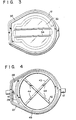
- FIG. 4 shows a modification of the filter support which may be used instead of the filter support 18 and which comprises a pair of support rods 42 and 43 arranged in the form of a cross and supported by the frame 11 within the filtering space defined thereby.
- These supports rods 42 and 43 have a plurality of projections or raised portions 44 provided above and below the crossing point.
- the raised portions 44 serve to support the filter elements 14 and 15 such that these elements are not in contact with the support rods 42 and 43 over the entire surfaces thereof.
- This filter support also has an edge portion 45 of the same construction as in the previous embodiment.
- the filter device according to the invention may, if necessary, be used by directly coupling a bottle needle and a dripping device to the side of the inlet port 16 and to the side of the outlet port 17, respectively.
Landscapes
- Health & Medical Sciences (AREA)
- Chemical Kinetics & Catalysis (AREA)
- Chemical & Material Sciences (AREA)
- Heart & Thoracic Surgery (AREA)
- Vascular Medicine (AREA)
- Biomedical Technology (AREA)
- Engineering & Computer Science (AREA)
- Anesthesiology (AREA)
- Cardiology (AREA)
- Hematology (AREA)
- Life Sciences & Earth Sciences (AREA)
- Animal Behavior & Ethology (AREA)
- General Health & Medical Sciences (AREA)
- Public Health (AREA)
- Veterinary Medicine (AREA)
- External Artificial Organs (AREA)
- Centrifugal Separators (AREA)
Claims (7)
Applications Claiming Priority (4)
| Application Number | Priority Date | Filing Date | Title |
|---|---|---|---|
| JP3994179A JPS55133256A (en) | 1979-04-03 | 1979-04-03 | Filter |
| JP39941/79 | 1979-04-03 | ||
| JP48705/79 | 1979-04-20 | ||
| JP4870579A JPS55139809A (en) | 1979-04-20 | 1979-04-20 | Filter |
Publications (2)
| Publication Number | Publication Date |
|---|---|
| EP0017873A1 EP0017873A1 (fr) | 1980-10-29 |
| EP0017873B1 true EP0017873B1 (fr) | 1984-07-04 |
Family
ID=26379342
Family Applications (1)
| Application Number | Title | Priority Date | Filing Date |
|---|---|---|---|
| EP80101817A Expired EP0017873B1 (fr) | 1979-04-03 | 1980-04-03 | Dispositif de filtrage de sang |
Country Status (6)
| Country | Link |
|---|---|
| US (1) | US4304670A (fr) |
| EP (1) | EP0017873B1 (fr) |
| AT (1) | ATE8205T1 (fr) |
| CA (1) | CA1138350A (fr) |
| DE (1) | DE3068415D1 (fr) |
| ES (1) | ES8104722A1 (fr) |
Families Citing this family (38)
| Publication number | Priority date | Publication date | Assignee | Title |
|---|---|---|---|---|
| US4369112A (en) * | 1981-03-18 | 1983-01-18 | Gelman Sciences Inc. | Filter device |
| USD319504S (en) | 1987-11-12 | 1991-08-27 | Terumo Kabushiki Kaisha | Blood processing filter |
| JPH0614969B2 (ja) * | 1988-03-15 | 1994-03-02 | テルモ株式会社 | 液体濾過装置 |
| USD328493S (en) | 1989-06-06 | 1992-08-04 | Terumo Kabushiki Kaisha | Blood processing filter |
| USD333348S (en) | 1990-01-25 | 1993-02-16 | Terumo Kabushiki Kaisha | Anesthesia solution filter |
| US5863436A (en) * | 1990-05-24 | 1999-01-26 | Pall Corporation | Venting system |
| US5126054A (en) * | 1990-05-24 | 1992-06-30 | Pall Corporation | Venting means |
| USD355973S (en) | 1993-02-10 | 1995-02-28 | Terumo Kabushiki Kaisha | Blood filter |
| USD360464S (en) | 1994-03-24 | 1995-07-18 | Gelman Sciences Inc. | Gas separating filter |
| USD367326S (en) | 1994-07-25 | 1996-02-20 | Pall Corporation | Ported filter for processing fluids |
| USD367532S (en) | 1994-08-10 | 1996-02-27 | Rela, Inc. | Medical filter |
| ATE265882T1 (de) | 1996-07-09 | 2004-05-15 | Pall Corp | Filtervorrichtung für biologische fluide mit einem leukocyten abreichernden medium |
| US6660171B2 (en) * | 2000-03-27 | 2003-12-09 | Peter Zuk, Jr. | High capacity gravity feed filter for filtering blood and blood products |
| DE10046173C2 (de) * | 2000-09-08 | 2003-04-03 | Inst Chemo Biosensorik | Vorrichtung und Verfahren zur Separation von ungelösten Bestandteilen aus biologischen Flüssigkeiten |
| MXPA05000816A (es) | 2002-07-19 | 2005-04-28 | Baxter Int | Sistemas y metodos para realizar dialisis peritoneal. |
| US7854845B2 (en) * | 2003-09-05 | 2010-12-21 | Hemerus Medical Llc | Biological fluid filtration apparatus |
| US7332096B2 (en) * | 2003-12-19 | 2008-02-19 | Fenwal, Inc. | Blood filter assembly having multiple filtration regions |
| US7128836B2 (en) * | 2004-03-08 | 2006-10-31 | Potito De Paolis | Dialysis device |
| CN100358590C (zh) * | 2004-03-19 | 2008-01-02 | 山东省千佛山医院 | 自动排气微栓过滤器 |
| WO2007086322A1 (fr) * | 2006-01-27 | 2007-08-02 | Jms Co., Ltd. | Appareil de filtration sanguine et méthode pour le produire |
| US7892331B2 (en) | 2007-10-01 | 2011-02-22 | Baxter International Inc. | Dialysis systems having air separation chambers with internal structures to enhance air removal |
| US7892332B2 (en) | 2007-10-01 | 2011-02-22 | Baxter International Inc. | Dialysis systems having air traps with internal structures to enhance air removal |
| US8444587B2 (en) | 2007-10-01 | 2013-05-21 | Baxter International Inc. | Fluid and air handling in blood and dialysis circuits |
| US7871462B2 (en) | 2007-10-01 | 2011-01-18 | Baxter International Inc. | Dialysis systems having air separation chambers with internal structures to enhance air removal |
| US8439858B2 (en) * | 2007-10-17 | 2013-05-14 | Medtronic, Inc. | Arterial blood filter |
| US8123947B2 (en) | 2007-10-22 | 2012-02-28 | Baxter International Inc. | Priming and air removal systems and methods for dialysis |
| US8114276B2 (en) | 2007-10-24 | 2012-02-14 | Baxter International Inc. | Personal hemodialysis system |
| US8057679B2 (en) | 2008-07-09 | 2011-11-15 | Baxter International Inc. | Dialysis system having trending and alert generation |
| US8382711B2 (en) | 2010-12-29 | 2013-02-26 | Baxter International Inc. | Intravenous pumping air management systems and methods |
| US9149157B2 (en) * | 2012-07-19 | 2015-10-06 | Michael Caplan | Universal pot lid handling device and method |
| US9486590B2 (en) | 2014-09-29 | 2016-11-08 | Fenwal, Inc. | Automatic purging of air from a fluid processing system |
| JP2018524718A (ja) | 2015-06-25 | 2018-08-30 | ガンブロ・ルンディア・エービーGambro Lundia Ab | 分散データベースを有する医療装置システム及び方法 |
| USD775343S1 (en) * | 2015-07-07 | 2016-12-27 | Tecscrn International Ltd. | Pleated laboratory screen |
| US10625009B2 (en) | 2016-02-17 | 2020-04-21 | Baxter International Inc. | Airtrap, system and method for removing microbubbles from a fluid stream |
| CN110100283B (zh) | 2016-12-21 | 2023-07-04 | 甘布罗伦迪亚股份公司 | 包括具有支持外域的安全集群域的信息技术基础架构的医疗设备系统 |
| JP7187487B2 (ja) * | 2017-08-14 | 2022-12-12 | テルモ株式会社 | 生体成分採取用カセット、生体成分採取キット、生体成分採取システム及び生体成分採取用カセットの製造方法 |
| USD1072221S1 (en) * | 2019-06-14 | 2025-04-22 | Stericube Surgical Systems, Llc | Filter |
| USD1090844S1 (en) * | 2021-05-06 | 2025-08-26 | Braun Melsungen Ag | Infusion filter |
Family Cites Families (16)
| Publication number | Priority date | Publication date | Assignee | Title |
|---|---|---|---|---|
| DE2050917B2 (de) * | 1970-10-16 | 1973-02-08 | Holstein & Kappert Maschinenfabrik Phoenix Gmbh | Verfahren und vorrichtung zum entsaeuern |
| US3730353A (en) * | 1970-12-28 | 1973-05-01 | Millipore Corp | Filter support and filter unit construction |
| AU465962B2 (en) * | 1972-06-16 | 1975-10-09 | Pall Corporation | Blood filter cascade |
| DE2356353C2 (de) * | 1973-11-12 | 1975-07-17 | B. Braun Melsungen Ag, 3508 Melsungen | Vorrichtung zum Filtern von Blut |
| US4038194A (en) * | 1974-04-19 | 1977-07-26 | Johnson & Johnson | Blood filter unit |
| GB1481572A (en) * | 1974-10-03 | 1977-08-03 | Pall Corp | Filter for filtration of blood |
| US4056476A (en) * | 1975-02-27 | 1977-11-01 | Johnson & Johnson | Blood filter media |
| DE2516175A1 (de) * | 1975-04-14 | 1976-10-21 | Fresenius Chem Pharm Ind | Blutfilter |
| US4009714A (en) * | 1975-07-30 | 1977-03-01 | Johnson & Johnson | Intravenous solution filter unit |
| US4021353A (en) * | 1975-11-20 | 1977-05-03 | Burron Medical Products, Inc. | Flat profile filter |
| IL51209A (en) * | 1976-03-25 | 1981-02-27 | Baxter Travenol Lab | Blood filter |
| US4170056A (en) * | 1976-03-25 | 1979-10-09 | Baxter Travenol Laboratories, Inc. | Blood filter |
| US4066556A (en) * | 1976-10-28 | 1978-01-03 | Johnson & Johnson | Fluid filter and method of making same |
| CH623746A5 (en) * | 1977-03-21 | 1981-06-30 | American Hospital Supply Corp | Mass transfer apparatus with a semipermeable membrane |
| AU3775578A (en) * | 1977-07-08 | 1980-01-10 | Johnson & Johnson | Vented filter assembly |
| DE7829319U1 (de) * | 1978-10-02 | 1979-03-22 | Hense, Peter, 4005 Meerbusch | Filter fuer fluessige medien |
-
1980
- 1980-03-27 US US06/134,427 patent/US4304670A/en not_active Expired - Lifetime
- 1980-03-31 CA CA000348854A patent/CA1138350A/fr not_active Expired
- 1980-04-01 ES ES490155A patent/ES8104722A1/es not_active Expired
- 1980-04-03 AT AT80101817T patent/ATE8205T1/de not_active IP Right Cessation
- 1980-04-03 EP EP80101817A patent/EP0017873B1/fr not_active Expired
- 1980-04-03 DE DE8080101817T patent/DE3068415D1/de not_active Expired
Also Published As
| Publication number | Publication date |
|---|---|
| EP0017873A1 (fr) | 1980-10-29 |
| DE3068415D1 (en) | 1984-08-09 |
| ES490155A0 (es) | 1981-04-16 |
| US4304670A (en) | 1981-12-08 |
| ES8104722A1 (es) | 1981-04-16 |
| ATE8205T1 (de) | 1984-07-15 |
| CA1138350A (fr) | 1982-12-28 |
Similar Documents
| Publication | Publication Date | Title |
|---|---|---|
| EP0017873A1 (fr) | Dispositif de filtrage de sang | |
| CA2230590C (fr) | Dispositif de filtration du sang fonctionnant en continu | |
| JP3358162B2 (ja) | 自給式フイルター装置 | |
| EP0302722B1 (fr) | Filtre à amorçage automatique | |
| CA1054073A (fr) | Element filtrant de fluides a purge de gaz | |
| US6010633A (en) | Method of preventing air from becoming entrapped within a filtration device | |
| US3905905A (en) | Filter unit | |
| US4009714A (en) | Intravenous solution filter unit | |
| EP0745398B1 (fr) | Réservoir cardio-chirurgical avec filtre interne | |
| EP0333119B1 (fr) | Dispositif de filtrage des liquides | |
| EP0008018A1 (fr) | Boîte filtrante | |
| JPH0121988B2 (fr) | ||
| CA2188689C (fr) | Sac filtrant souple | |
| EP1381438B1 (fr) | Filtre de fluides biologiques | |
| CA2671077C (fr) | Chambre de transfert de sang | |
| US6660171B2 (en) | High capacity gravity feed filter for filtering blood and blood products | |
| US6251292B1 (en) | Method of preventing air from becoming entrapped within a filtration device | |
| WO2003026773A1 (fr) | Dispositif et systeme de filtration de fluides biologiques | |
| US4957629A (en) | Obstetrical filter and trap | |
| JP3272782B2 (ja) | 液体処理器 | |
| JP2799179B2 (ja) | 液体処理器 | |
| JP4162315B2 (ja) | 血液リザーバ | |
| EP2298428A1 (fr) | Système de filtration de liquide | |
| GB2122911A (en) | Blood filter |
Legal Events
| Date | Code | Title | Description |
|---|---|---|---|
| PUAI | Public reference made under article 153(3) epc to a published international application that has entered the european phase |
Free format text: ORIGINAL CODE: 0009012 |
|
| AK | Designated contracting states |
Designated state(s): AT BE CH DE FR GB IT LI NL SE |
|
| 17P | Request for examination filed |
Effective date: 19801219 |
|
| ITF | It: translation for a ep patent filed | ||
| GRAA | (expected) grant |
Free format text: ORIGINAL CODE: 0009210 |
|
| AK | Designated contracting states |
Designated state(s): AT BE CH DE FR GB IT LI NL SE |
|
| REF | Corresponds to: |
Ref document number: 8205 Country of ref document: AT Date of ref document: 19840715 Kind code of ref document: T |
|
| REF | Corresponds to: |
Ref document number: 3068415 Country of ref document: DE Date of ref document: 19840809 |
|
| ET | Fr: translation filed | ||
| PLBE | No opposition filed within time limit |
Free format text: ORIGINAL CODE: 0009261 |
|
| STAA | Information on the status of an ep patent application or granted ep patent |
Free format text: STATUS: NO OPPOSITION FILED WITHIN TIME LIMIT |
|
| 26N | No opposition filed | ||
| ITTA | It: last paid annual fee | ||
| EAL | Se: european patent in force in sweden |
Ref document number: 80101817.7 |
|
| PGFP | Annual fee paid to national office [announced via postgrant information from national office to epo] |
Ref country code: GB Payment date: 19950324 Year of fee payment: 16 |
|
| PGFP | Annual fee paid to national office [announced via postgrant information from national office to epo] |
Ref country code: DE Payment date: 19950410 Year of fee payment: 16 |
|
| PGFP | Annual fee paid to national office [announced via postgrant information from national office to epo] |
Ref country code: FR Payment date: 19950411 Year of fee payment: 16 |
|
| PGFP | Annual fee paid to national office [announced via postgrant information from national office to epo] |
Ref country code: AT Payment date: 19950412 Year of fee payment: 16 |
|
| PGFP | Annual fee paid to national office [announced via postgrant information from national office to epo] |
Ref country code: CH Payment date: 19950413 Year of fee payment: 16 |
|
| PGFP | Annual fee paid to national office [announced via postgrant information from national office to epo] |
Ref country code: SE Payment date: 19950419 Year of fee payment: 16 |
|
| PGFP | Annual fee paid to national office [announced via postgrant information from national office to epo] |
Ref country code: NL Payment date: 19950430 Year of fee payment: 16 |
|
| PGFP | Annual fee paid to national office [announced via postgrant information from national office to epo] |
Ref country code: BE Payment date: 19950510 Year of fee payment: 16 |
|
| PG25 | Lapsed in a contracting state [announced via postgrant information from national office to epo] |
Ref country code: GB Effective date: 19960403 Ref country code: AT Effective date: 19960403 |
|
| PG25 | Lapsed in a contracting state [announced via postgrant information from national office to epo] |
Ref country code: SE Effective date: 19960404 |
|
| PG25 | Lapsed in a contracting state [announced via postgrant information from national office to epo] |
Ref country code: LI Effective date: 19960430 Ref country code: CH Effective date: 19960430 Ref country code: BE Effective date: 19960430 |
|
| BERE | Be: lapsed |
Owner name: TERUMO CORP. Effective date: 19960430 |
|
| PG25 | Lapsed in a contracting state [announced via postgrant information from national office to epo] |
Ref country code: NL Effective date: 19961101 |
|
| GBPC | Gb: european patent ceased through non-payment of renewal fee |
Effective date: 19960403 |
|
| REG | Reference to a national code |
Ref country code: CH Ref legal event code: PL |
|
| PG25 | Lapsed in a contracting state [announced via postgrant information from national office to epo] |
Ref country code: FR Effective date: 19961227 |
|
| PG25 | Lapsed in a contracting state [announced via postgrant information from national office to epo] |
Ref country code: DE Effective date: 19970101 |
|
| NLV4 | Nl: lapsed or anulled due to non-payment of the annual fee |
Effective date: 19961101 |
|
| EUG | Se: european patent has lapsed |
Ref document number: 80101817.7 |
|
| REG | Reference to a national code |
Ref country code: FR Ref legal event code: ST |