EP0018005A1 - Eléments de montage de structures tridimensionnelles - Google Patents
Eléments de montage de structures tridimensionnelles Download PDFInfo
- Publication number
- EP0018005A1 EP0018005A1 EP80102113A EP80102113A EP0018005A1 EP 0018005 A1 EP0018005 A1 EP 0018005A1 EP 80102113 A EP80102113 A EP 80102113A EP 80102113 A EP80102113 A EP 80102113A EP 0018005 A1 EP0018005 A1 EP 0018005A1
- Authority
- EP
- European Patent Office
- Prior art keywords
- flange
- pipe
- tube
- kit according
- connecting piece
- Prior art date
- Legal status (The legal status is an assumption and is not a legal conclusion. Google has not performed a legal analysis and makes no representation as to the accuracy of the status listed.)
- Granted
Links
- 238000004519 manufacturing process Methods 0.000 title claims description 4
- 238000010276 construction Methods 0.000 title 1
- 239000000725 suspension Substances 0.000 claims description 6
- 210000002105 tongue Anatomy 0.000 claims description 5
- 230000008878 coupling Effects 0.000 claims description 4
- 238000010168 coupling process Methods 0.000 claims description 4
- 238000005859 coupling reaction Methods 0.000 claims description 4
- 230000001427 coherent effect Effects 0.000 claims 1
- 238000003491 array Methods 0.000 abstract 1
- 244000089486 Phragmites australis subsp australis Species 0.000 description 3
- 238000006073 displacement reaction Methods 0.000 description 3
- 210000001503 joint Anatomy 0.000 description 3
- 239000002184 metal Substances 0.000 description 3
- 238000010079 rubber tapping Methods 0.000 description 2
- 239000011324 bead Substances 0.000 description 1
- 210000000078 claw Anatomy 0.000 description 1
- 230000005484 gravity Effects 0.000 description 1
- 230000003993 interaction Effects 0.000 description 1
Images


Classifications
-
- F—MECHANICAL ENGINEERING; LIGHTING; HEATING; WEAPONS; BLASTING
- F21—LIGHTING
- F21V—FUNCTIONAL FEATURES OR DETAILS OF LIGHTING DEVICES OR SYSTEMS THEREOF; STRUCTURAL COMBINATIONS OF LIGHTING DEVICES WITH OTHER ARTICLES, NOT OTHERWISE PROVIDED FOR
- F21V21/00—Supporting, suspending, or attaching arrangements for lighting devices; Hand grips
- F21V21/005—Supporting, suspending, or attaching arrangements for lighting devices; Hand grips for several lighting devices in an end-to-end arrangement, i.e. light tracks
-
- F—MECHANICAL ENGINEERING; LIGHTING; HEATING; WEAPONS; BLASTING
- F16—ENGINEERING ELEMENTS AND UNITS; GENERAL MEASURES FOR PRODUCING AND MAINTAINING EFFECTIVE FUNCTIONING OF MACHINES OR INSTALLATIONS; THERMAL INSULATION IN GENERAL
- F16B—DEVICES FOR FASTENING OR SECURING CONSTRUCTIONAL ELEMENTS OR MACHINE PARTS TOGETHER, e.g. NAILS, BOLTS, CIRCLIPS, CLAMPS, CLIPS OR WEDGES; JOINTS OR JOINTING
- F16B7/00—Connections of rods or tubes, e.g. of non-circular section, mutually, including resilient connections
-
- F—MECHANICAL ENGINEERING; LIGHTING; HEATING; WEAPONS; BLASTING
- F21—LIGHTING
- F21S—NON-PORTABLE LIGHTING DEVICES; SYSTEMS THEREOF; VEHICLE LIGHTING DEVICES SPECIALLY ADAPTED FOR VEHICLE EXTERIORS
- F21S2/00—Systems of lighting devices, not provided for in main groups F21S4/00 - F21S10/00 or F21S19/00, e.g. of modular construction
-
- F—MECHANICAL ENGINEERING; LIGHTING; HEATING; WEAPONS; BLASTING
- F21—LIGHTING
- F21Y—INDEXING SCHEME ASSOCIATED WITH SUBCLASSES F21K, F21L, F21S and F21V, RELATING TO THE FORM OR THE KIND OF THE LIGHT SOURCES OR OF THE COLOUR OF THE LIGHT EMITTED
- F21Y2103/00—Elongate light sources, e.g. fluorescent tubes
Definitions
- the invention relates to a kit for the production of trusses, in particular light pipe systems, with at least one tube which is divided along axially parallel surface lines into two interlocking tubular shells, one of which is connected to end flanges on the end faces, and with at least one connecting piece with at least one contact surface for End flanges of the pipe shells.
- Such a kit is known from DE-OS 25 56 813.
- the end flange of an upper pipe shell is guided against a connecting piece, for example a node, and then a sleeve is inserted through a hole in the inside of the closing flange into a corresponding hole in the connecting piece from the inside of the pipe and through a bayonet fitting or the like. locked.
- a connecting piece for example a node
- a sleeve is inserted through a hole in the inside of the closing flange into a corresponding hole in the connecting piece from the inside of the pipe and through a bayonet fitting or the like. locked.
- a certain longitudinal displacement within the upper tube shell is required, so that the interior of the upper tube shell cannot be used completely to accommodate lighting fixtures and their additional units.
- the end flange and the connecting piece interlock with one another in a type of coupling claws, they have to be pushed apart slightly in the axial direction during disassembly. This is often not possible
- the invention has for its object to provide a kit for the production of trusses according to the generic term such that no intervention in the interior of the pipe shells is required for the assembly and disassembly of the system and the assembly and disassembly only radial displacements of the tube shells in relation to the connectors required.
- end flange is open on one side and essentially horseshoe-shaped, that in the interior of the annular contact surface of the connecting piece there is a projecting tube extension to be gripped by the end flange, and that an arcuate closure flange is provided which can be assembled and locked with the end flange around the tube attachment.
- the pipe socket which is encompassed by the closure and closure flange.
- the tube extension preferably has an outwardly projecting flange, behind which an arcuate Support webs that start from the end and closure flange. This results in a tensile connection between the connector and an adjacent pipe.
- the end and the closure flange have corresponding shapes, so that they can be plugged together smoothly and thereby form a circular outer shape.
- the locking flange can be latched, for example, with the aid of a leaf spring attached to the locking flange and provided with two free legs, which is hooked into a suitable inner profile of the upper tubular shell.
- upper and lower pipe shell refers to the predominantly used operating position and the representation in the drawing.
- these pipe shells can also be arranged in other positions relative to one another, since the unit comprising the end flange and the closure flange can be freely rotated around the pipe extension. Possibly. a stop is provided which limits the rotation to an angle of approximately 360 °, so that supply lines routed inside the pipes and connecting pieces are prevented from being twisted off.
- Connecting pieces can be provided in the form of nodes, for example with six pipe lugs, corner pieces, pipe bends or individual butt joints. Free pipe attachments can be covered with suitable cover caps.
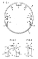
- the tube shown in FIG. 1 in an enlarged cross section is composed of an upper tube shell 10 and a lower tube shell 12, through which the cylindrical tube, viewed in cross section, is divided into generatrices approximately in a ratio of two thirds to one third.
- the pipe shells 10, 12 are extruded profiles made of metal or plastic with an overall cylindrical surface.
- the lower pipe shell 12 has on its longitudinal edges resilient clamping strips 14, 16, which spring over clamping beads 18, 20 on the longitudinal edges of the upper pipe shells 10, so that there is a firm but detachable connection.
- the pipe shells can be in other positions than those shown in FIG. 1, so that the identification as the upper and lower pipe shells is only intended to serve as an explanation.
- the upper pipe shell 10 has in the upper apex line an undercut chamber 22 which enters the interior of the pipe shell and into which, for example, metal strips (not shown) with threaded bores can be inserted to form suspension points. Furthermore, on the right and left in FIG. 1, on the mutually opposite inner sides of the upper tubular shell 10, cross-sectionally substantially rectangular attachment strips 24, 26, in which axially parallel channels 28, 30 with an essentially circular cross-section run, which have slots 32, 34 in Direction of the central axis of the tube are open. Further extension strips 36, 38 with a hook-shaped cross section are located on both sides of the chamber 22.
- the pipe shells 10, 12 can be produced as an endless profile, they can be cut to any length.
- the lower tube shell 12 can be omitted in whole or in part, provided there are fluorescent tubes, busbars or in the interior of the upper tube shell 10 Like. Be housed.
- an end flange 40 is attached to both end faces, which has the shape of a ring or horseshoe open on one side.
- the end flange has on the right and left side in FIG. 2 countersunk holes 42, 44, which serve to receive screws, not shown, which can be screwed into the channels 28, 30 of the upper pipe shell 10.
- Self-tapping screws are expediently used.
- Guide pins 46, 48 which project from the end flange 40 in the upper area on the right and left in FIG. 2, engage in the angles formed between the outer wall of the upper pipe shell 10 and the extension strips 36, 38 and serve for further locking.
- a window 50 in the upper middle region of the end flange 40 lies in the assembled position in the extension of the chamber 22 and thus serves to receive the metal strip or the like, not shown.
- Another countersunk bore 52 in the end flange receives a plastic spigot, not shown, on which later to be discussed again.
- the inner, U-shaped recess 54 of the end flange is surrounded by an upstanding web 56 which runs on the inner edge of the end flange.
- the end flange 40 is mounted on the upper pipe shell 10 such that the web 56 protrudes into the interior of the pipe shell.
- an arcuate closure flange 58 according to FIGS. 4 and 5 is provided, the outer radius of which corresponds to that of the end flange 40.
- the closure flange 58 has on its inside edge a projecting web 60, the inner radius of which corresponds to the inner radius of the web 56 of the end flange 40 speaks.
- a correspondingly curved leaf spring 62 is fastened on the outside of the arch of the web 60 with the aid of a self-tapping screw, not shown, to be screwed into a bore 64.
- the leaf spring 62 has at its two free ends double-angled hooks 66, which will be discussed later.
- the web 60 has a recess or a recess 70 along its free edge on the inside of the arch.
- the web 60 is penetrated by a counterbore 72, into which a stop pin (not shown) is inserted, which will be discussed again later.
- the end flange 40 and the closure flange 58 are matched to one another in their dimensions such that they form a closed ring.
- the lower end faces 74 of the end flange 40 in FIG. 2 lie against the lower end faces 76 of the closure flange 58 in FIG. 4, while the web 60 of the closure flange enters between the legs of the U-shaped web 56 of the end flange such that a substantially circular free interior is formed.
- the closure flange 58 is a separate mounting part which is not fixedly connected to the lower pipe shell 12 but only supports it at the angle between the web 60 and the flange bend, as will be described later should be explained in more detail.
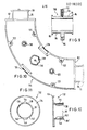
- FIG. 6 shows, as an example of a connecting piece for individual tubes, a node 78 with a cube-shaped or essentially spherical base body 80 1 on which there are six annular contact surfaces 82, each at an angle of 90 ° to one another, which form connection options for six pipes, as may be necessary in a spatial framework.
- the node 80 is designed as a hollow body so that supply lines, in particular power lines, can be routed through the node into the interior of the individual tubes.
- Pipe lugs 84 project from the inner edge of the support surfaces 82, which are also hollow on the inside and thus create an open connection to the interior of the junction 80.
- the pipe lugs 84 have circumferential flanges 86 on their free edge, on each of which a stop 88 is provided, the function of which will be discussed later.
- FIG. 7 The interaction of a connecting piece, such as the node 80 according to FIG. 6, the pipe shells of FIG. 1 and the: flanges of FIGS. 2 and 4 is illustrated in FIG. 7 in a longitudinal section.
- the individual parts of FIG. 7 have the same reference numbers as in FIGS. 1 to 6.
- a connecting piece 84 extends from a connecting piece, which is only indicated on the left-hand side in FIG. 7, such as a junction 80, and has a circumferential flange 86 at the outer end thereof.
- a stop 88 is provided on the flange 86.
- closure flange 58 is pushed from the opposite, i.e. the lower side in FIG. 7, against the tube extension 84, the web 60 engaging behind the flange 86 of the tube extension 84, but overlapping the flange 86 in the region of the recess 70 of the closure flange, as is the case 7 emerges.
- the leaf spring 62 of the closure flange 58 enters the interior of the upper tubular shell 10, the hooks 86, 88 of the leaf spring being locked in a suitable position, for example behind the extension strips 24, 26. By pressing together the legs of the leaf spring 62, this latching connection can be released again. If a closed tube is to be used, the lower tube shell 12 is then pressed against the upper tube shell 10 in the manner shown in FIG. 1, while at the same time covering the web 60 of the closure flange.
- the abovementioned stop 88 is located on the flange 86 of the pipe extension 84, which in connection with that mentioned in connection with FIG. 7 indicated hinge pin 90 cooperates in the bore 72 of the closure flange.
- a counterbore 52 according to FIG. 2 can be used, slightly protruding plastic pin can be provided, which exerts a braking effect due to friction on the contact surface 82.
- a threaded bore 92 is provided in the closure flange 58, which, with the aid of a suitable screw, enables locking in any angular position.
- the pipe lugs 84 shown in FIG. 6 with the flanges 86 and the stops 88 represent a uniform element of all connecting parts, as will be explained in the following with the aid of a few further examples.
- FIG 8 shows, for example, a corner piece 94 with two pipe lugs 84 arranged at an angle of 90 ° to one another.
- the corner piece 94 is designed as a hollow part.
- the corner piece 84 is composed of two shells and clamped together using screws and nuts 96.98.
- Adjustment pins 100, 102 indicated by dashed lines are used for precise position fixing.
- a cap 104 indicated by dashed lines can be broken out to accommodate additional lights and the like.
- a bore 106 serves to receive suspension members, not shown.
- Fig. 9 shows another connector in the form of a pipe coupling for a vertical butt joint. It is essentially an annular disk 110, from whose two sides in turn pipe lugs 84 with flanges 86 extend. If the disc is not designed as a circular ring, but as a closed plate and only carries a pipe extension 84 on one side, a connecting piece of this type can be used as an end plate or cover for pipes.
- a radial bore 112 in the disc serves for receiving suspension elements.
- a further, axially parallel bore 114 in the disk can optionally be used to hold a locking screw, but is not necessary. agile.
- a connecting piece shown in FIG. 10 in the form of a pipe bend 116 is used for the right-angled connection of two pipes, not shown, in a larger bend than is possible with a corner piece 94 according to FIG. 8.
- the pipe bend 106 can consist of two separate shells which are clamped together by screws or nuts 118, 120.
- four adjustment pins 122 with corresponding bores are provided in the other shell.
- Caps 124, 126 can be broken out if additional lights or the like are to be installed.
- a recessed hexagonal plate 128 with a threaded bore 130 serves to receive suspension elements.
- An end cap 132 for tubes shown in FIGS. 11 and 12 comprises a circular plate 134, from the surface of which in turn a tube extension, which in this case is designated 84 '.
- This tube attachment differs from the tube attachment described so far by a number of axially parallel slots 136, 138, 140, 142, through which the tube attachment 84 'is divided into a number of parallel tongues, of which at least the tongues designated 144 and 146 have a flange section 86.
- the tongues 144, 146 are resilient and allow the end cap to be locked in the end of a tube (not shown in FIGS. 11 and 12) or an arrangement of the end flange 40 and the closure flange 58.
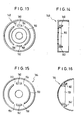
- FIG. 13 and 14 show a cover cap 148 for pipe attachments of connecting pieces.
- an overall circular tube extension 150 which is divided by slots 154, 156, 158, 160 into a number of arcuate sections, two sections of which as Tongues 160, 162 are formed with inwardly projecting hooks which engage over the flange 86 of the pipe lugs 84.
- FIGS. 15 and 16 Another cover cap in the shape of a hemisphere is designated by 164 in FIGS. 15 and 16.
- 164 In the interior of the hemisphere 164 there is a locking mechanism which corresponds to that of FIGS. 13 and 14 and therefore need not be explained again.
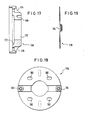
- FIG. 17 shows a section through an overall circular end piece 166 for fastening a pipe to the wall or ceiling.
- An annular contact surface 168 corresponds to the contact surface of the connecting pieces, which is designated 82 for example for the junction 78 according to FIG. 6.
- a bore 170 for receiving the pipe extension 84 of the connecting pieces.
- an enlarged recess 172 adjoins the bore 170, in which the flange 86 of a pipe extension 84 can be fixed, for example with the aid of a circlip.
- the end piece 166 can be fastened by means of screws, not shown, which are passed through bores 174, 176, on a base plate 178, which is shown in FIGS has been assembled. Two so-called Börti nuts 182, 184 are fastened on the base plate 178 and can be gripped by screws through the bores 174, 176 of the end piece 166.
Landscapes
- Engineering & Computer Science (AREA)
- General Engineering & Computer Science (AREA)
- Mechanical Engineering (AREA)
- Quick-Acting Or Multi-Walled Pipe Joints (AREA)
- Joining Of Building Structures In Genera (AREA)
- Fastening Of Light Sources Or Lamp Holders (AREA)
Priority Applications (1)
| Application Number | Priority Date | Filing Date | Title |
|---|---|---|---|
| AT80102113T ATE707T1 (de) | 1979-04-19 | 1980-04-18 | Bausatz zur herstellung von raumfachwerken. |
Applications Claiming Priority (2)
| Application Number | Priority Date | Filing Date | Title |
|---|---|---|---|
| DE2915778 | 1979-04-19 | ||
| DE2915778A DE2915778C2 (de) | 1979-04-19 | 1979-04-19 | Raumfachwerk, insbesondere Lichtrohrsystem |
Publications (2)
| Publication Number | Publication Date |
|---|---|
| EP0018005A1 true EP0018005A1 (fr) | 1980-10-29 |
| EP0018005B1 EP0018005B1 (fr) | 1982-02-17 |
Family
ID=6068692
Family Applications (1)
| Application Number | Title | Priority Date | Filing Date |
|---|---|---|---|
| EP80102113A Expired EP0018005B1 (fr) | 1979-04-19 | 1980-04-18 | Eléments de montage de structures tridimensionnelles |
Country Status (3)
| Country | Link |
|---|---|
| EP (1) | EP0018005B1 (fr) |
| AT (1) | ATE707T1 (fr) |
| DE (1) | DE2915778C2 (fr) |
Cited By (2)
| Publication number | Priority date | Publication date | Assignee | Title |
|---|---|---|---|---|
| EP0115576A3 (fr) * | 1983-01-08 | 1985-09-04 | Günter Kotzolt | Eléments pour le montage de bandes lumineuses ou de structures tridimensionnelles |
| DE3604319A1 (de) * | 1986-02-12 | 1987-08-13 | Hoffmeister Leuchten Kg | Vorrichtung zur verbindung von einen laengsschlitz aufweisenden verkleidungsrohren fuer lichtschienen |
Families Citing this family (1)
| Publication number | Priority date | Publication date | Assignee | Title |
|---|---|---|---|---|
| CN114051571B (zh) * | 2019-07-10 | 2024-08-23 | 昕诺飞控股有限公司 | 线性灯具连接器组件 |
Citations (2)
| Publication number | Priority date | Publication date | Assignee | Title |
|---|---|---|---|---|
| US2408547A (en) * | 1944-08-18 | 1946-10-01 | Standard Cabinet Works Inc | Coupling |
| DE2556813A1 (de) * | 1975-12-17 | 1977-07-07 | Wolfgang Fenner | Bausatz zum herstellen von raumfachwerken fuer ausstellungs- und ladenbau |
-
1979
- 1979-04-19 DE DE2915778A patent/DE2915778C2/de not_active Expired
-
1980
- 1980-04-18 AT AT80102113T patent/ATE707T1/de not_active IP Right Cessation
- 1980-04-18 EP EP80102113A patent/EP0018005B1/fr not_active Expired
Patent Citations (2)
| Publication number | Priority date | Publication date | Assignee | Title |
|---|---|---|---|---|
| US2408547A (en) * | 1944-08-18 | 1946-10-01 | Standard Cabinet Works Inc | Coupling |
| DE2556813A1 (de) * | 1975-12-17 | 1977-07-07 | Wolfgang Fenner | Bausatz zum herstellen von raumfachwerken fuer ausstellungs- und ladenbau |
Cited By (3)
| Publication number | Priority date | Publication date | Assignee | Title |
|---|---|---|---|---|
| EP0115576A3 (fr) * | 1983-01-08 | 1985-09-04 | Günter Kotzolt | Eléments pour le montage de bandes lumineuses ou de structures tridimensionnelles |
| US4628660A (en) * | 1983-01-08 | 1986-12-16 | Guenter Kotzolt | Construction kit for producing light-tube systems for three-dimensional frameworks |
| DE3604319A1 (de) * | 1986-02-12 | 1987-08-13 | Hoffmeister Leuchten Kg | Vorrichtung zur verbindung von einen laengsschlitz aufweisenden verkleidungsrohren fuer lichtschienen |
Also Published As
| Publication number | Publication date |
|---|---|
| DE2915778C2 (de) | 1981-10-01 |
| ATE707T1 (de) | 1982-03-15 |
| DE2915778A1 (de) | 1980-10-23 |
| EP0018005B1 (fr) | 1982-02-17 |
Similar Documents
| Publication | Publication Date | Title |
|---|---|---|
| EP0379496B1 (fr) | Raccord de tuyaux permettant la realisation de points de jonction | |
| CH645448A5 (de) | Anschlussarmatur mit flexiblem wellschlauch. | |
| DE3843096C2 (de) | Befestigungseinrichtung für Verkleidungen | |
| DE4229533A1 (de) | Vorrichtung zum verbinden von zwei rohren | |
| DE4411220A1 (de) | Rohrmanschette | |
| DE60210703T2 (de) | Anordung zur Befestigung eines selbsttragenden Spots an einer gespannten Decke | |
| EP0018005B1 (fr) | Eléments de montage de structures tridimensionnelles | |
| EP3527873A1 (fr) | Ensemble destiné à la réalisation d'un émetteur encastré | |
| DE19540111B4 (de) | Elektronik- und Instrumentierungsgehäuse | |
| DE4210625C1 (de) | Winkelverbindung, insbesondere für Auslegerrohre für Leuchten | |
| DE20114345U1 (de) | Vorrichtung zum Halten von Versorgungsleitungen an einem mehrachsigen Industrieroboter | |
| DE19646541C1 (de) | Bausatz miteinander verbindbarer Profilelemente | |
| DE3737171C2 (fr) | ||
| DE2928917C2 (de) | Säulenartiges Stützrohr für Kleinbauten, insbesondere für Skelettrahmenkonstruktionen | |
| DE3808334C1 (en) | Clamp for fastening a pipe | |
| DE69230108T2 (de) | Kupplungsvorrichtung | |
| EP0176864B1 (fr) | Dispositif de décoration | |
| EP0959536A1 (fr) | Bloc multiprises | |
| DE29915780U1 (de) | Schwenkbare Leuchtenhalterung | |
| DE9406350U1 (de) | Verbindungseinrichtung | |
| DE10053195C1 (de) | Klemmverbindung | |
| DE102006020224A1 (de) | Reflektorvorrichtung für eine Beleuchtungsvorrichtung | |
| DE2516142C3 (de) | Drehkippgelenk für Leuchten | |
| DE19805052C1 (de) | Rasterdecke mit an kreuzförmigen Kupplungselementen geklemmten, glatten Rohren | |
| DE317708C (fr) |
Legal Events
| Date | Code | Title | Description |
|---|---|---|---|
| PUAI | Public reference made under article 153(3) epc to a published international application that has entered the european phase |
Free format text: ORIGINAL CODE: 0009012 |
|
| AK | Designated contracting states |
Designated state(s): AT BE CH FR GB IT LU NL SE |
|
| 17P | Request for examination filed | ||
| ITF | It: translation for a ep patent filed | ||
| GRAA | (expected) grant |
Free format text: ORIGINAL CODE: 0009210 |
|
| AK | Designated contracting states |
Designated state(s): AT BE CH FR GB IT LU NL SE |
|
| REF | Corresponds to: |
Ref document number: 707 Country of ref document: AT Date of ref document: 19820315 Kind code of ref document: T |
|
| ITTA | It: last paid annual fee | ||
| PGFP | Annual fee paid to national office [announced via postgrant information from national office to epo] |
Ref country code: GB Payment date: 19930401 Year of fee payment: 14 |
|
| PGFP | Annual fee paid to national office [announced via postgrant information from national office to epo] |
Ref country code: BE Payment date: 19930414 Year of fee payment: 14 |
|
| PGFP | Annual fee paid to national office [announced via postgrant information from national office to epo] |
Ref country code: SE Payment date: 19930415 Year of fee payment: 14 Ref country code: LU Payment date: 19930415 Year of fee payment: 14 |
|
| PGFP | Annual fee paid to national office [announced via postgrant information from national office to epo] |
Ref country code: FR Payment date: 19930416 Year of fee payment: 14 |
|
| PGFP | Annual fee paid to national office [announced via postgrant information from national office to epo] |
Ref country code: AT Payment date: 19930427 Year of fee payment: 14 |
|
| PGFP | Annual fee paid to national office [announced via postgrant information from national office to epo] |
Ref country code: NL Payment date: 19930430 Year of fee payment: 14 |
|
| PGFP | Annual fee paid to national office [announced via postgrant information from national office to epo] |
Ref country code: CH Payment date: 19930504 Year of fee payment: 14 |
|
| EPTA | Lu: last paid annual fee | ||
| PG25 | Lapsed in a contracting state [announced via postgrant information from national office to epo] |
Ref country code: LU Free format text: LAPSE BECAUSE OF NON-PAYMENT OF DUE FEES Effective date: 19940418 Ref country code: GB Effective date: 19940418 Ref country code: AT Effective date: 19940418 |
|
| PG25 | Lapsed in a contracting state [announced via postgrant information from national office to epo] |
Ref country code: SE Effective date: 19940419 |
|
| PG25 | Lapsed in a contracting state [announced via postgrant information from national office to epo] |
Ref country code: LI Effective date: 19940430 Ref country code: CH Effective date: 19940430 Ref country code: BE Effective date: 19940430 |
|
| BERE | Be: lapsed |
Owner name: KOTZOLT GUNTER Effective date: 19940430 |
|
| PG25 | Lapsed in a contracting state [announced via postgrant information from national office to epo] |
Ref country code: NL Effective date: 19941101 |
|
| GBPC | Gb: european patent ceased through non-payment of renewal fee |
Effective date: 19940418 |
|
| NLV4 | Nl: lapsed or anulled due to non-payment of the annual fee | ||
| PG25 | Lapsed in a contracting state [announced via postgrant information from national office to epo] |
Ref country code: FR Effective date: 19941229 |
|
| REG | Reference to a national code |
Ref country code: CH Ref legal event code: PL |
|
| EUG | Se: european patent has lapsed |
Ref document number: 80102113.0 Effective date: 19941110 |
|
| REG | Reference to a national code |
Ref country code: FR Ref legal event code: ST |
|
| PLBE | No opposition filed within time limit |
Free format text: ORIGINAL CODE: 0009261 |
|
| STAA | Information on the status of an ep patent application or granted ep patent |
Free format text: STATUS: NO OPPOSITION FILED WITHIN TIME LIMIT |