EP0018059A1 - Installation et procédé pour le chauffage et le refroidissement de produits métalliques - Google Patents
Installation et procédé pour le chauffage et le refroidissement de produits métalliques Download PDFInfo
- Publication number
- EP0018059A1 EP0018059A1 EP80300183A EP80300183A EP0018059A1 EP 0018059 A1 EP0018059 A1 EP 0018059A1 EP 80300183 A EP80300183 A EP 80300183A EP 80300183 A EP80300183 A EP 80300183A EP 0018059 A1 EP0018059 A1 EP 0018059A1
- Authority
- EP
- European Patent Office
- Prior art keywords
- products
- pit
- gas
- installation
- heating
- Prior art date
- Legal status (The legal status is an assumption and is not a legal conclusion. Google has not performed a legal analysis and makes no representation as to the accuracy of the status listed.)
- Withdrawn
Links
- 238000010438 heat treatment Methods 0.000 title claims abstract description 26
- 238000001816 cooling Methods 0.000 title claims abstract description 25
- 238000000034 method Methods 0.000 title claims description 16
- 239000002184 metal Substances 0.000 title claims description 13
- 238000009434 installation Methods 0.000 claims abstract description 27
- 238000005096 rolling process Methods 0.000 claims abstract description 21
- 229910000831 Steel Inorganic materials 0.000 claims description 10
- 239000010959 steel Substances 0.000 claims description 10
- 230000006698 induction Effects 0.000 claims description 2
- 239000000047 product Substances 0.000 description 68
- 239000007789 gas Substances 0.000 description 25
- 238000000137 annealing Methods 0.000 description 4
- 239000011819 refractory material Substances 0.000 description 3
- 239000011265 semifinished product Substances 0.000 description 3
- 238000010583 slow cooling Methods 0.000 description 3
- 238000004891 communication Methods 0.000 description 2
- 230000003134 recirculating effect Effects 0.000 description 2
- 239000002912 waste gas Substances 0.000 description 2
- CWYNVVGOOAEACU-UHFFFAOYSA-N Fe2+ Chemical compound [Fe+2] CWYNVVGOOAEACU-UHFFFAOYSA-N 0.000 description 1
- 229910000746 Structural steel Inorganic materials 0.000 description 1
- 229910045601 alloy Inorganic materials 0.000 description 1
- 239000000956 alloy Substances 0.000 description 1
- 239000010425 asbestos Substances 0.000 description 1
- 238000005336 cracking Methods 0.000 description 1
- 238000010586 diagram Methods 0.000 description 1
- 230000000694 effects Effects 0.000 description 1
- -1 for example Substances 0.000 description 1
- 238000005098 hot rolling Methods 0.000 description 1
- 206010022000 influenza Diseases 0.000 description 1
- 238000003754 machining Methods 0.000 description 1
- 230000000704 physical effect Effects 0.000 description 1
- 230000000717 retained effect Effects 0.000 description 1
- 229910052895 riebeckite Inorganic materials 0.000 description 1
- 210000002268 wool Anatomy 0.000 description 1
Images

Classifications
-
- C—CHEMISTRY; METALLURGY
- C21—METALLURGY OF IRON
- C21D—MODIFYING THE PHYSICAL STRUCTURE OF FERROUS METALS; GENERAL DEVICES FOR HEAT TREATMENT OF FERROUS OR NON-FERROUS METALS OR ALLOYS; MAKING METAL MALLEABLE, e.g. BY DECARBURISATION OR TEMPERING
- C21D1/00—General methods or devices for heat treatment, e.g. annealing, hardening, quenching or tempering
- C21D1/84—Controlled slow cooling
-
- C—CHEMISTRY; METALLURGY
- C21—METALLURGY OF IRON
- C21D—MODIFYING THE PHYSICAL STRUCTURE OF FERROUS METALS; GENERAL DEVICES FOR HEAT TREATMENT OF FERROUS OR NON-FERROUS METALS OR ALLOYS; MAKING METAL MALLEABLE, e.g. BY DECARBURISATION OR TEMPERING
- C21D9/00—Heat treatment, e.g. annealing, hardening, quenching or tempering, adapted for particular articles; Furnaces therefor
- C21D9/0062—Heat-treating apparatus with a cooling or quenching zone
Definitions
- This invention relates to methods of and apparatus for the control of heating and cooling of metal products especially semi-finished products such as steel billets, bars and rounds.
- the purpose of such heating and cooling is to obtain desired physical properties in the product particularly to facilitate dividing the product into shorter lengths or machining it or both.
- an installation for the heat treatment of metal products comprising an elongated pit to receive the products, a removable lid for the pit, a gas inlet at one end of the pit, a gas outlet at the other end of the pit, a duct connecting the inlet and the outlet and a means to circulate gas through the circuit comprising a pit and duct, and means to heat the products in the pit.
- cold products could be laid in the pit, heated to a desired temperature by the heating means and then subjected to a desired rate of controlled cooling.
- the means for heating the products could be a burner associated with the inlet to heat the gas entering the pit or could be resistance or induction heating means associated with the pit to heat the products directly.
- the means to circulate the gas through the pit and the duct is a fan which is preferably located at the output end of the pit.
- valve means associated with the outlet from the pit and selectively operable to direct gases leaving the pit to the duct or to the exhaust.
- cool gas e.g. air
- the valve means can be operated to discharge the cool air through the exhaust at the outlet end of the pit thus avoiding cooling of the circulating duct.
- the deflectors may be chains or mesh carrying refractory materials such as, for example, asbestos wool.
- the invention also includes the combination of a rolling mill for metal products, an elongate pit adjacent the exit from the rolling mill, means to transfer products directly from the rolling mill exit to the pit, a removable lid for the pit and means associated with the pit for heating products therein.
- the invention also includes a rolling mill for metal products having, adjacent the exit therefrom an installation as above described and means to transfer the products directly from the mill exit to the installation.
- the transfer means may comprise an apertured rack to hold metal products at the exit from the rolling mill and a plurality of aligned grabs carried by a crane and arranged to engage the products in the apertures in the rack.
- the invention also provides a method of heat treating metal products in an installation as described above comprising placing the products in the pit and heating them to a desired temperature.
- the invention further provides a method of heat treating, hot-rolled products comprising placing them in an enclosure while still hot from the rolling mill, cooling the products by circulating gas between them and using the heat rejected by the products to the gas to equalise the temperature of the products and to heat the enclosure and a gas circulating duct.
- the method may include heating the products or the gas to equalise the temperature thereof before cooling.
- the method may include re-heating the products in the pit after initial cooling and then again cooling the products, the heating and cooling taking place while gas is being circulated between the products.
- the method may include rapid cooling of the products in the pit by introducing cool air into the pit to flow between the products but preventing said cool air from circulating through the gas circulating duct.
- metal products as used herein will be understood to refer to any metal semi-finished products and particularly but not exclusively to ferrous products such as steel billets, bars or rounds.
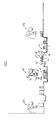
- the installation comprises a pit indicated generally at 10 and a recirculation duct indicated generally at 11.
- the pit comprises a framework of structural steel some of the beams of which are indicated at 12 and this is lined with a steel lining 13 which in turn is lined with a lining of refractory material 14.
- the pit is elongated and has an inlet for gas at one end indicated at 15 and an outlet for gas at the other end indicated at 16.
- the inlet and the outlet are connected by the recirculating duct 11.
- a burner section is indicated at 17 adjacent the inlet 15 and the duct comprises a hairpin bend section 18 connecting the burner section 17 to a straight section 19.
- the straight part 19 of the duct is connected by a straight portion 20 to a fan housing 21 which is open to the outlet 16.
- a paddle type fan 22 is mounted in the fan housing on a shaft 23 and is driven by an electric motor 24 via Vee belts 25.
- a valve 26 pivotable about a vertical axis 27 between the position shown in which the duct parts 19 and 20 are in communication and another extreme position in which it is inclined to the right in Figure 2 so as to place the duct part 20 in communication with the flue 28.
- the floor of the pit has a slot 28 therein which leads to a waste gas flue 29 which in turn leads to a common flue 30 for a number of installations arranged side by side.
- the pit has a lid 34 which is made up on a steel frame and is lined with refractory material at 35.
- Flexible deflectors one of which is shown at 36, extend from the lid so as to rest upon a supply of products within the pit, the products not being shown in the drawing.
- the exit from a rolling mill is indicated at 40 and comprises a roller table 41 and an adjustable stop 42.
- the exit from the rolling mill is located between two groups of installations similar to that described in relation to Figures 1 and 2, one of the groups to the left of the exit being indicated at 43 and the group to the right of the exit being indicated at 44.
- Running above the installations is an overhead crane indicated generally at 45 and moveable between the extreme positions indicated at 45a and 45b.
- the crane comprises a number of grabs, one of which is shown at 46 and having a pair of jaws 47, 48 which are shown in their closed positions but which can retract into the grab body.
- Adjacent to the roller table is a rack 49 which is apertured at intervals along its length. It is to be noted that there is a table 50 and that the rack has a junction at 51 with the table. The products are pushed off the table over the junction 51 and into the rack 49. This is effected by a push-off mechanism 52.
- the operation of the arrangement is as follows.
- the products are delivered from the rolling mill hot onto the roller table 41 until they engage the stop 42.
- the products are removed from the table singly or in groups by means of the push-off mechanism 52 so that a group of products accumulates in the apertured rack 49.
- the crane 45 then is moved over the rack and the grabs 46 are dropped down with the jaws 47 and 48 opened so that each grab is arranged in an aperture of the rack.
- the grabs are lowered until the jaws 47 and 48 of each grab can encircle the products in the rack and the jaws 47 and 48 are then closed and the grabs lifted to lift a group of products out of the rack. It will be seen that the products are supported at a number of positions corresponding to the number of grabs 46.
- the group of products is then moved by the crane to position over one of the pits and the grabs can be lowered as shown for example in dotted lines at 46a to deposit the products in the pit.
- the lid of the pit is placed in position over the pit so that the flexible deflectors 36 rest on the top of the pile of products in the pit.
- the floor of a pit is made as a labyrinth and the effect of this and the deflectors is that, as will be described below, when gas is circulated through the pit and the circulation duct the gas is forced to flow between and around the products rather than taking the shortest path over the products or under them.
- the temperature of the products will be equalised and this may require operation of the burner because the ends of the products will have cooled relative to the middle portions thereof. Once the ends of the products have been heated, the burner is turned off and the products are allowed to cool while gas is circulated through the pit and the recirculation duct by operation of the fan 22. The heat rejected from the products heats the pit and the recirculation duct.
- the products are allowed to cool as before through the critical range.
- the burner section is operated and the products are reheated through the critical range and are then held at a temperature above the critical range.
- gas is recirculated through the pit and the recirculation duct by the fan and the burners are operated as required to maintain the temperature.
- the products After the products have been held at the required temperature for the required time, they are cooled at a controlled rate by recirculating the gas through the pit and recirculation duct without operation of the burner and then are rapidly cooled after they have been cooled below the critical range as described above.
- the products can be rapidly cooled by letting cold air into the inlet 32 and exhausting it to the flue 28 and then held at a comparatively low temperature for a desired time and then re-heated by operation of the burner section, held within the critical range, allowed to cool and then held just below the critical range and then rapidly cooled.
Landscapes
- Chemical & Material Sciences (AREA)
- Engineering & Computer Science (AREA)
- Physics & Mathematics (AREA)
- Thermal Sciences (AREA)
- Crystallography & Structural Chemistry (AREA)
- Mechanical Engineering (AREA)
- Materials Engineering (AREA)
- Metallurgy (AREA)
- Organic Chemistry (AREA)
- Heat Treatments In General, Especially Conveying And Cooling (AREA)
Applications Claiming Priority (2)
| Application Number | Priority Date | Filing Date | Title |
|---|---|---|---|
| GB7902420 | 1979-01-23 | ||
| GB7902420 | 1979-01-23 |
Publications (1)
| Publication Number | Publication Date |
|---|---|
| EP0018059A1 true EP0018059A1 (fr) | 1980-10-29 |
Family
ID=10502685
Family Applications (1)
| Application Number | Title | Priority Date | Filing Date |
|---|---|---|---|
| EP80300183A Withdrawn EP0018059A1 (fr) | 1979-01-23 | 1980-01-21 | Installation et procédé pour le chauffage et le refroidissement de produits métalliques |
Country Status (2)
| Country | Link |
|---|---|
| EP (1) | EP0018059A1 (fr) |
| ES (1) | ES487953A0 (fr) |
Citations (10)
| Publication number | Priority date | Publication date | Assignee | Title |
|---|---|---|---|---|
| DE433279C (de) * | 1925-03-15 | 1926-08-27 | Siemens Elektrowaerme Ges M B | Verfahren zum Betrieb von Blankgluehoefen |
| DE488450C (de) * | 1926-01-01 | 1929-12-30 | Reischach & Co G M B H | Verfahren zur gleichmaessigen Erwaermung von Metallen oder aehnlichen Stoffen und zum Einhalten einer gleichmaessigen Temperatur durch einen umlaufenden Heizgasstrom |
| FR860311A (fr) * | 1938-09-20 | 1941-01-11 | Curran Brothers Ltd | Perfectionnements apportés aux fours de chauffage |
| US2277592A (en) * | 1940-04-18 | 1942-03-24 | Salem Engineering Company | Method and apparatus for heating metal objects |
| DE722948C (de) * | 1938-03-26 | 1942-07-24 | Aeg | Ofen zum abwechselnden Erwaermen und Abkuehlen des Gluehgutes |
| FR932145A (fr) * | 1946-08-10 | 1948-03-12 | Heurtey & Cie | Perfectionnements aux fours à circulation forcée |
| US2619341A (en) * | 1947-09-26 | 1952-11-25 | Sunbeam Corp | Heat-treating furnace |
| GB930063A (en) * | 1958-07-10 | 1963-07-03 | Steel Co Of Wales Ltd | Improvements in, or relating to, annealing furnaces |
| US3470624A (en) * | 1966-12-13 | 1969-10-07 | Hispano Suiza Sa | Tempering furnaces and method |
| US4032365A (en) * | 1976-05-05 | 1977-06-28 | Caterpillar Tractor Co. | Warm form cooling and heat recovery tunnel |
-
1980
- 1980-01-21 EP EP80300183A patent/EP0018059A1/fr not_active Withdrawn
- 1980-01-23 ES ES487953A patent/ES487953A0/es active Granted
Patent Citations (10)
| Publication number | Priority date | Publication date | Assignee | Title |
|---|---|---|---|---|
| DE433279C (de) * | 1925-03-15 | 1926-08-27 | Siemens Elektrowaerme Ges M B | Verfahren zum Betrieb von Blankgluehoefen |
| DE488450C (de) * | 1926-01-01 | 1929-12-30 | Reischach & Co G M B H | Verfahren zur gleichmaessigen Erwaermung von Metallen oder aehnlichen Stoffen und zum Einhalten einer gleichmaessigen Temperatur durch einen umlaufenden Heizgasstrom |
| DE722948C (de) * | 1938-03-26 | 1942-07-24 | Aeg | Ofen zum abwechselnden Erwaermen und Abkuehlen des Gluehgutes |
| FR860311A (fr) * | 1938-09-20 | 1941-01-11 | Curran Brothers Ltd | Perfectionnements apportés aux fours de chauffage |
| US2277592A (en) * | 1940-04-18 | 1942-03-24 | Salem Engineering Company | Method and apparatus for heating metal objects |
| FR932145A (fr) * | 1946-08-10 | 1948-03-12 | Heurtey & Cie | Perfectionnements aux fours à circulation forcée |
| US2619341A (en) * | 1947-09-26 | 1952-11-25 | Sunbeam Corp | Heat-treating furnace |
| GB930063A (en) * | 1958-07-10 | 1963-07-03 | Steel Co Of Wales Ltd | Improvements in, or relating to, annealing furnaces |
| US3470624A (en) * | 1966-12-13 | 1969-10-07 | Hispano Suiza Sa | Tempering furnaces and method |
| US4032365A (en) * | 1976-05-05 | 1977-06-28 | Caterpillar Tractor Co. | Warm form cooling and heat recovery tunnel |
Also Published As
| Publication number | Publication date |
|---|---|
| ES8101938A1 (es) | 1980-12-16 |
| ES487953A0 (es) | 1980-12-16 |
Similar Documents
| Publication | Publication Date | Title |
|---|---|---|
| US3048383A (en) | Furnace or like system for gas-supporting and treating flat work | |
| US3063878A (en) | Method of and apparatus for annealing | |
| EP0359756B1 (fr) | Systeme de four a chambres multiples, a foyer rotatif a usages multiples | |
| EP1078106B1 (fr) | Procede et appareil de traitement a lit fluidise | |
| US1949716A (en) | Method of and apparatus for heattreating | |
| US3953247A (en) | Method for heat treatment of material to be worked on, especially of aluminium or magnesium alloys | |
| US4225121A (en) | Energy efficient heat-treating furnace system | |
| CN106170568B (zh) | 用于在环底平炉中对细长扁平的金属物料、尤其是轧制铝锭进行热处理的方法和设备 | |
| NL8104247A (nl) | Werkwijze voor de warmtebehandeling van draadbundels en doorvoeroven voor het uitvoeren van deze werkwijze. | |
| US5143558A (en) | Method of heat treating metal parts in an integrated continuous and batch furnace system | |
| US4154433A (en) | Continuous atmosphere controlled furnaces | |
| US4397449A (en) | Apparatus for cooling hot-rolled wire rods | |
| US4449923A (en) | Continuous heat-treating furnace | |
| US4427371A (en) | Pusher furnace with soak zone lifter | |
| US4468262A (en) | Method of cooling hot-rolled wire rods | |
| EP0018059A1 (fr) | Installation et procédé pour le chauffage et le refroidissement de produits métalliques | |
| US4664359A (en) | Furnace for heat treating light alloy ingots | |
| US5314169A (en) | Method and apparatus for heat treating elongate metallic products | |
| US3623714A (en) | Method of and apparatus for operating a furnace | |
| GB2045408A (en) | Furnace system | |
| JP2576966B2 (ja) | めっきにおける連続べーキング炉 | |
| EP0237334A2 (fr) | Procédé et appareil pour la cuisson de produits céramiques | |
| RU2147108C1 (ru) | Электропечь "прэтти" | |
| US3930831A (en) | Furnace for heat treating glass sheet material | |
| JPS5924544A (ja) | 鍛造品の熱処理方法および装置 |
Legal Events
| Date | Code | Title | Description |
|---|---|---|---|
| PUAI | Public reference made under article 153(3) epc to a published international application that has entered the european phase |
Free format text: ORIGINAL CODE: 0009012 |
|
| AK | Designated contracting states |
Designated state(s): AT BE DE FR GB IT LU NL SE |
|
| 17P | Request for examination filed |
Effective date: 19810429 |
|
| PLAA | Information modified related to event that no opposition was filed |
Free format text: ORIGINAL CODE: 0009299DELT |
|
| STAA | Information on the status of an ep patent application or granted ep patent |
Free format text: STATUS: THE APPLICATION IS DEEMED TO BE WITHDRAWN |
|
| 18D | Application deemed to be withdrawn |
Effective date: 19830831 |
|
| RIN1 | Information on inventor provided before grant (corrected) |
Inventor name: APPLETON, PETER JOHN Inventor name: HARRIS, AUSTIN TOYNE |