EP0018152A1 - Entseuchungsverfahren - Google Patents
Entseuchungsverfahren Download PDFInfo
- Publication number
- EP0018152A1 EP0018152A1 EP80301113A EP80301113A EP0018152A1 EP 0018152 A1 EP0018152 A1 EP 0018152A1 EP 80301113 A EP80301113 A EP 80301113A EP 80301113 A EP80301113 A EP 80301113A EP 0018152 A1 EP0018152 A1 EP 0018152A1
- Authority
- EP
- European Patent Office
- Prior art keywords
- components
- grit
- nozzle
- water
- mixture
- Prior art date
- Legal status (The legal status is an assumption and is not a legal conclusion. Google has not performed a legal analysis and makes no representation as to the accuracy of the status listed.)
- Granted
Links
Images
Classifications
-
- G—PHYSICS
- G21—NUCLEAR PHYSICS; NUCLEAR ENGINEERING
- G21F—PROTECTION AGAINST X-RADIATION, GAMMA RADIATION, CORPUSCULAR RADIATION OR PARTICLE BOMBARDMENT; TREATING RADIOACTIVELY CONTAMINATED MATERIAL; DECONTAMINATION ARRANGEMENTS THEREFOR
- G21F9/00—Treating radioactively contaminated material; Decontamination arrangements therefor
-
- B—PERFORMING OPERATIONS; TRANSPORTING
- B24—GRINDING; POLISHING
- B24C—ABRASIVE OR RELATED BLASTING WITH PARTICULATE MATERIAL
- B24C11/00—Selection of abrasive materials or additives for abrasive blasts
-
- B—PERFORMING OPERATIONS; TRANSPORTING
- B24—GRINDING; POLISHING
- B24C—ABRASIVE OR RELATED BLASTING WITH PARTICULATE MATERIAL
- B24C1/00—Methods for use of abrasive blasting for producing particular effects; Use of auxiliary equipment in connection with such methods
-
- G—PHYSICS
- G21—NUCLEAR PHYSICS; NUCLEAR ENGINEERING
- G21F—PROTECTION AGAINST X-RADIATION, GAMMA RADIATION, CORPUSCULAR RADIATION OR PARTICLE BOMBARDMENT; TREATING RADIOACTIVELY CONTAMINATED MATERIAL; DECONTAMINATION ARRANGEMENTS THEREFOR
- G21F9/00—Treating radioactively contaminated material; Decontamination arrangements therefor
- G21F9/28—Treating solids
Definitions
- This invention relates to decontamination methods and more particularly to methods for decontaminating components of nuclear power plants.
- the present invention resides in a method of decontaminating components, especially components of nuclear power plants, wherein the components are exposed to a water jet to remove the radioactive particles therefrom and, at the same time, to wash the radioactive particles away from said components without damaging the metal surface of the component characterized in that said water jet is a water-grit mixture having a grit concentration of between 3% to 7% by weight for intense particle removing action.
- the flow rate and pressure of the water jet are controlled so that a thin layer of metal oxide deposits may be removed from the component without damaging the metal component -itself thereby reducing the radiation field of the component.
- the grit types, size, and concentration in the water jet are also controlled along with the distance of the nozzle from the surface of the component and the angle of impingement so that an optimum level of decontamination is achieved without deterioration of the metal surface.
- the invention is a method for decontaminating components of nuclear power plants so that working personnel may perform operations thereon.
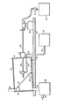
- apparatus for performing the decontamination method comprises a platform 10 for supporting container 12 which may be a steel drum having a closure plate 14.
- Container 12 comprises supports 16 for supporting the specimen 18 to be decontaminated.
- Container 12 also has a vent 20 and a drain 22.
- Container 12 is arranged such that the front portion thereof is supported by a bar 24 so that container 12 is tilted such that liquid within container 12 will flow through drain 22.
- Drain 22 is connected to filter 26 which may be a 5-25 micron filter bag chosen from those well known in the art.
- Filter 26 is connected to a pipe 28 which is connected to a drain for disposing of or recirculating the water used in the decontamination process.
- a 2.3 cm diameter tube 30 extends through universal joint 32 and closure plate 14 so that the front end of tube 30 is disposed within container 12.
- a nozzle 34 is mounted on the front end of tube 30 and is also connected to flexible hose 36.
- Nozzle 34 may be chosen from those well known in the art such as a "Dynajector" manufactured by the Aqua-Dyne Engineering, Inc. of Houston, Texas.
- Flexible hose 36 extends through closure plate 14 and is connected to grit supply 38 for supplying grit to nozzle 34.
- Tube 30 is connected to pump 40 which may be a 40 horsepower pump which is also connected to water supply 42 for supplying water to nozzle 34.
- Nozzle 34 provides a mechanism for mixing the grit and water and for emitting the water-grit mixture from nozzle 34 toward specimen 18.
- Tube 30 is also attached to drive mechanism 44 which may be a mechanism for controlling the horizontal movement of tube 30 and nozzle 34.
- Drive mechanism 44 may be chosen from those well known in the art.
- the decontamination method comprises introducing water through tube 30 at a pressure between 140 kg/cm and 190 kgjcm 2 .
- the water flow rate at this pressure should be approximately 30 to 34 liters per minute through nozzle 34.
- grit may be used for mixing with the water such as alumina or magnetite.
- the grit size should be approximately 120 to 325 mesh size in accordance with United States Sieve Series Mesh Sizes. It is important to note that the grit concentration in the water spray should be approximately 3% to approximately 7% by weight.
- the nozzle be placed approximately 15 cm to 25 cm from the surface of specimen 18.
- nozzle 34 should be arranged at approximately between 30° to 70° with respect to the longitudinal axis of tube 30 so that the water-grit mixture impinges the surface of specimen 18 at approximately between a 30°-70° angle and preferably at about 45°.
- a test specimen 18 having a top surface that has been contaminated with radioactivity is placed within container 12 and supported by supports 16 as shown in the drawing.
- Closure plate 14 is then attached to container 12 such that tube 30, nozzle 34, and flexible hose 36 are arranged as shown in the drawing.
- Universal joint 32 which also comprises a clamping mechanism is arranged such that the flow of the water-grit mixture from nozzle 34 is directed to the proper elevation of specimen 18. At this point, nozzle 34 is approximately 15 to 25 cm from the surface of the specimen 18.
- pump 40 is activated which causes water to be' pumped from water supply 42 through tube 30 and into nozzle 34.
- nozzle 34 The flow of water through nozzle 34 creates a vacuum in nozzle 34 which draws the grit from grit supply 38 through flexible hose 36 where it mixes with the water in nozzle 34. The water-grit mixture is then directed toward the specimen 18. Simultaneously, drive mechanism 44 is activated which causes tube 30 and nozzle 34 to move in a horizontal line across specimen 18 at a speed of approximately 30 cm per minute to approximately 90 cm per minute. The speed of travel of nozzle 34 is correlated with the water-grit flow rate so as to provide effective decontamination without excessive deterioration of the metal of specimen 18.
- nozzle 34 has made a complete horizontal pass of specimen 18, universal joint 32 is readjusted so that nozzle 34 is directed toward a different vertical elevation of specimen 18 and at the same 15 to 25 cm distance. Then, drive mechanism 44 is reversed so that nozzle 34 makes a similar horizontal pass of specimen 18 but at a different elevation. In this manner, an entire sweeping of specimen 18 may be made.
- an additional nozzle 34 may be attached to tube 30 and also arranged at approximately a 45° angle and opposing the first nozzle 34 so as to provide a dual nozzle arrangement.
- a test of the decontamination method was made with the following parameters: Two passes were made across the surface of the specimen, one pass each at opposing 45° angles. This ensured cleaning of both sides of the irregularities in the surface of the specimen. Results of the tests show that 98.3% to 99.9% of the radioactive contamination was removed from the sample simulating nuclear reactor component surfaces. None of the samples suffered perceptible surface damage.
- the decontamination method may be used on nuclear reactor components such as nuclear steam generators with the equipment adapted to be placed within the nuclear component. Therefore, the invention provides a decontamination method for lowering the radiation field of nuclear reactor power components so that working personnel may enter the component and perform operations thereon.
Landscapes
- Engineering & Computer Science (AREA)
- Mechanical Engineering (AREA)
- Physics & Mathematics (AREA)
- General Engineering & Computer Science (AREA)
- High Energy & Nuclear Physics (AREA)
- Cleaning In General (AREA)
- Cleaning By Liquid Or Steam (AREA)
- Detergent Compositions (AREA)
- Perforating, Stamping-Out Or Severing By Means Other Than Cutting (AREA)
- Working Measures On Existing Buildindgs (AREA)
Applications Claiming Priority (2)
| Application Number | Priority Date | Filing Date | Title |
|---|---|---|---|
| US2959879A | 1979-04-12 | 1979-04-12 | |
| US29598 | 1979-04-12 |
Publications (2)
| Publication Number | Publication Date |
|---|---|
| EP0018152A1 true EP0018152A1 (de) | 1980-10-29 |
| EP0018152B1 EP0018152B1 (de) | 1983-09-14 |
Family
ID=21849874
Family Applications (1)
| Application Number | Title | Priority Date | Filing Date |
|---|---|---|---|
| EP80301113A Expired EP0018152B1 (de) | 1979-04-12 | 1980-04-08 | Entseuchungsverfahren |
Country Status (9)
| Country | Link |
|---|---|
| EP (1) | EP0018152B1 (de) |
| JP (1) | JPS55141700A (de) |
| KR (1) | KR830002114B1 (de) |
| CA (1) | CA1130565A (de) |
| DE (1) | DE3064799D1 (de) |
| ES (1) | ES8301386A1 (de) |
| FR (1) | FR2454160A1 (de) |
| YU (1) | YU42329B (de) |
| ZA (1) | ZA802191B (de) |
Cited By (5)
| Publication number | Priority date | Publication date | Assignee | Title |
|---|---|---|---|---|
| US4494607A (en) * | 1983-05-09 | 1985-01-22 | Ford Michael B | Method of cleaning and inhibiting sucker rod corrosion |
| EP0023820B1 (de) * | 1979-08-02 | 1985-02-13 | Westinghouse Electric Corporation | Dekontaminierungsapparat |
| EP0158743A1 (de) * | 1984-01-26 | 1985-10-23 | Ernst Schmutz GmbH | Verfahren und Vorrichtung zum Reinigen radioaktiv verseuchter Anlagenteile |
| US5347557A (en) * | 1993-03-03 | 1994-09-13 | Siemens Aktiengesellschaft | Apparatus for decontaminating radioactively contaminated surfaces |
| US5637030A (en) * | 1994-02-17 | 1997-06-10 | Minerals Research & Recovery, Inc. | Abrasive formulation for waterjet cutting and method employing same |
Families Citing this family (4)
| Publication number | Priority date | Publication date | Assignee | Title |
|---|---|---|---|---|
| JPS6042440B2 (ja) * | 1980-07-29 | 1985-09-21 | アブレイシブ・デベロツプメンツ・リミテツド | 汚染除去装置 |
| EP0116663A1 (de) * | 1983-02-19 | 1984-08-29 | NTG Neue Technologien GmbH & Co. KG | Verfahren zur Dekontamination der inneren Oberfläche eines Reaktorbehälters |
| KR101406938B1 (ko) * | 2012-04-15 | 2014-06-12 | 원대연 | 복부재가 다양한 형태의 문양을 갖는 복합거더 |
| KR20240024174A (ko) * | 2021-06-29 | 2024-02-23 | 쉐이프 테크놀로지스 그룹, 인크. | 위험 물품 구성요소에 접근 및 분해를 위한 유체 제트 시스템 및 사용 방법 |
Citations (1)
| Publication number | Priority date | Publication date | Assignee | Title |
|---|---|---|---|---|
| FR2127021A1 (de) * | 1971-02-17 | 1972-10-13 | Siemens Ag |
Family Cites Families (3)
| Publication number | Priority date | Publication date | Assignee | Title |
|---|---|---|---|---|
| US3130083A (en) * | 1960-01-27 | 1964-04-21 | Henry C Turner | Treatment of articles made of leatherlike material |
| JPS51121698A (en) * | 1975-04-18 | 1976-10-25 | Toshiba Corp | Method and its device for removing pollution from an instrument pollut ed by radioactivity |
| JPS5252473A (en) * | 1975-10-24 | 1977-04-27 | Toshiba Corp | Fur removing system |
-
1980
- 1980-03-07 YU YU636/80A patent/YU42329B/xx unknown
- 1980-03-14 CA CA347,699A patent/CA1130565A/en not_active Expired
- 1980-04-08 DE DE8080301113T patent/DE3064799D1/de not_active Expired
- 1980-04-08 EP EP80301113A patent/EP0018152B1/de not_active Expired
- 1980-04-10 KR KR1019800001487A patent/KR830002114B1/ko not_active Expired
- 1980-04-11 JP JP4700280A patent/JPS55141700A/ja active Granted
- 1980-04-11 FR FR8008179A patent/FR2454160A1/fr not_active Withdrawn
- 1980-04-11 ZA ZA00802191A patent/ZA802191B/xx unknown
- 1980-04-11 ES ES490511A patent/ES8301386A1/es not_active Expired
Patent Citations (1)
| Publication number | Priority date | Publication date | Assignee | Title |
|---|---|---|---|---|
| FR2127021A1 (de) * | 1971-02-17 | 1972-10-13 | Siemens Ag |
Non-Patent Citations (1)
| Title |
|---|
| EUR 5186 d; Europaische Atomgemeinschaft-EURATOM. 1968 MOSSELMANS G. and NIENHAUS J.: "Auswal von Abrasiven und Badsusatzen fur die Dekontaminierung mittels Schlammstrahlen". * Abstract; pages 5-8; pages 17-20 * * |
Cited By (5)
| Publication number | Priority date | Publication date | Assignee | Title |
|---|---|---|---|---|
| EP0023820B1 (de) * | 1979-08-02 | 1985-02-13 | Westinghouse Electric Corporation | Dekontaminierungsapparat |
| US4494607A (en) * | 1983-05-09 | 1985-01-22 | Ford Michael B | Method of cleaning and inhibiting sucker rod corrosion |
| EP0158743A1 (de) * | 1984-01-26 | 1985-10-23 | Ernst Schmutz GmbH | Verfahren und Vorrichtung zum Reinigen radioaktiv verseuchter Anlagenteile |
| US5347557A (en) * | 1993-03-03 | 1994-09-13 | Siemens Aktiengesellschaft | Apparatus for decontaminating radioactively contaminated surfaces |
| US5637030A (en) * | 1994-02-17 | 1997-06-10 | Minerals Research & Recovery, Inc. | Abrasive formulation for waterjet cutting and method employing same |
Also Published As
| Publication number | Publication date |
|---|---|
| ZA802191B (en) | 1981-04-29 |
| KR830003115A (ko) | 1983-05-31 |
| JPS55141700A (en) | 1980-11-05 |
| JPS6333117B2 (de) | 1988-07-04 |
| EP0018152B1 (de) | 1983-09-14 |
| FR2454160A1 (fr) | 1980-11-07 |
| YU63680A (en) | 1984-04-30 |
| CA1130565A (en) | 1982-08-31 |
| KR830002114B1 (ko) | 1983-10-12 |
| ES490511A0 (es) | 1982-12-01 |
| YU42329B (en) | 1988-08-31 |
| DE3064799D1 (en) | 1983-10-20 |
| ES8301386A1 (es) | 1982-12-01 |
Similar Documents
| Publication | Publication Date | Title |
|---|---|---|
| US5046289A (en) | System and method for cleaning the inner surface of tubular members | |
| DE2107479C3 (de) | Verfahren zur Dekontaminierung der Oberflächen von Kernreaktorbauteilen | |
| EP0091646B1 (de) | Dekontaminationsverfahren mittels Laser | |
| EP0532544B1 (de) | Verfahren und vorrichtung zur dekontamination radioaktiv kontaminierter oberflächen | |
| EP0018152B1 (de) | Entseuchungsverfahren | |
| EP0112576A1 (de) | Ultraschall-Dekontaminationsroboter | |
| US4496519A (en) | Nuclear reactor vessel decontamination systems | |
| EP0023820B1 (de) | Dekontaminierungsapparat | |
| JP2002311191A (ja) | 放射性除染対象物の除染設備 | |
| JPH10142376A (ja) | 炉心シュラウドの交換方法 | |
| WO1999041753A1 (de) | Verfahren zum zertrennen eines radioaktiven bauteils eines kernreaktors und vorrichtung hierzu | |
| JP2002311193A (ja) | 放射性汚染物の除染装置 | |
| KR101176436B1 (ko) | 증기발생기 오염튜브다발 내부표면을 제염하기 위한 연마분사장치 | |
| KR102613149B1 (ko) | 수류에 의해 회전하는 와이어브러쉬를 이용한 반응기, 열교환기 튜브의 세관시 친환경 습식 자동 스케일등 처리 및 처리수 재사용장치 | |
| US9793022B1 (en) | Method of decontamination for a high activity nuclear waste polluted storage canister | |
| DE4306631A1 (de) | Vorrichtung zur Dekontamination radioaktiv kontaminierter Oberflächen | |
| JP2001264490A (ja) | 弁の除染方法及び除染装置 | |
| JPH11118991A (ja) | 水タンクの壁面塗装装置 | |
| Wallace et al. | Contamination of a soft-drink manufacturing plant by 210Po | |
| KR20240031200A (ko) | 딥러닝 기반 방사성 오염 탱크의 고압수 제염 장치 및 이를 이용한 제염 방법 | |
| JPS5815760B2 (ja) | 放射性物質汚染機器類の除染方法 | |
| Bodin et al. | Cogema experience on decontamination and underwater automatically remote cutting using ultra high pressure water during nuclear decommissioning operations. The Aquarad robot | |
| Wojcik et al. | Decontamination apparatus | |
| Lacy et al. | Ontario Hydro decontamination experience | |
| Tripp | Decontamination technologies evaluations |
Legal Events
| Date | Code | Title | Description |
|---|---|---|---|
| PUAI | Public reference made under article 153(3) epc to a published international application that has entered the european phase |
Free format text: ORIGINAL CODE: 0009012 |
|
| AK | Designated contracting states |
Designated state(s): BE CH DE GB IT SE |
|
| 17P | Request for examination filed |
Effective date: 19810422 |
|
| ITF | It: translation for a ep patent filed | ||
| GRAA | (expected) grant |
Free format text: ORIGINAL CODE: 0009210 |
|
| AK | Designated contracting states |
Designated state(s): BE CH DE GB IT LI SE |
|
| REF | Corresponds to: |
Ref document number: 3064799 Country of ref document: DE Date of ref document: 19831020 |
|
| PGFP | Annual fee paid to national office [announced via postgrant information from national office to epo] |
Ref country code: SE Payment date: 19840331 Year of fee payment: 5 Ref country code: BE Payment date: 19840331 Year of fee payment: 5 |
|
| PGFP | Annual fee paid to national office [announced via postgrant information from national office to epo] |
Ref country code: DE Payment date: 19840521 Year of fee payment: 5 |
|
| PLBI | Opposition filed |
Free format text: ORIGINAL CODE: 0009260 |
|
| PGFP | Annual fee paid to national office [announced via postgrant information from national office to epo] |
Ref country code: CH Payment date: 19840625 Year of fee payment: 5 |
|
| 26 | Opposition filed |
Opponent name: CENTRAL ELECTRICITY GENERATING BOARD Effective date: 19840614 Opponent name: KRAFTWERK UNION AKTIENGESELLSCHAFT Effective date: 19840613 |
|
| RDAG | Patent revoked |
Free format text: ORIGINAL CODE: 0009271 |
|
| STAA | Information on the status of an ep patent application or granted ep patent |
Free format text: STATUS: PATENT REVOKED |
|
| GBPR | Gb: patent revoked under art. 102 of the ep convention designating the uk as contracting state | ||
| 27W | Patent revoked |
Effective date: 19850323 |
|
| REG | Reference to a national code |
Ref country code: CH Ref legal event code: PL |
|
| BERE | Be: lapsed |
Owner name: WESTINGHOUSE ELECTRIC CORP. Effective date: 19850408 |
|
| EUG | Se: european patent has lapsed |
Ref document number: 80301113.9 Effective date: 19860128 |
|
| PLAB | Opposition data, opponent's data or that of the opponent's representative modified |
Free format text: ORIGINAL CODE: 0009299OPPO |