EP0018168A2 - Abscheider zur Trennung von Öl und Gas - Google Patents
Abscheider zur Trennung von Öl und Gas Download PDFInfo
- Publication number
- EP0018168A2 EP0018168A2 EP80301144A EP80301144A EP0018168A2 EP 0018168 A2 EP0018168 A2 EP 0018168A2 EP 80301144 A EP80301144 A EP 80301144A EP 80301144 A EP80301144 A EP 80301144A EP 0018168 A2 EP0018168 A2 EP 0018168A2
- Authority
- EP
- European Patent Office
- Prior art keywords
- liquid
- vessel
- gas
- separator
- vortex
- Prior art date
- Legal status (The legal status is an assumption and is not a legal conclusion. Google has not performed a legal analysis and makes no representation as to the accuracy of the status listed.)
- Granted
Links
Images

Classifications
-
- B—PERFORMING OPERATIONS; TRANSPORTING
- B01—PHYSICAL OR CHEMICAL PROCESSES OR APPARATUS IN GENERAL
- B01D—SEPARATION
- B01D19/00—Degasification of liquids
- B01D19/0042—Degasification of liquids modifying the liquid flow
- B01D19/0052—Degasification of liquids modifying the liquid flow in rotating vessels, vessels containing movable parts or in which centrifugal movement is caused
- B01D19/0057—Degasification of liquids modifying the liquid flow in rotating vessels, vessels containing movable parts or in which centrifugal movement is caused the centrifugal movement being caused by a vortex, e.g. using a cyclone, or by a tangential inlet
-
- B—PERFORMING OPERATIONS; TRANSPORTING
- B04—CENTRIFUGAL APPARATUS OR MACHINES FOR CARRYING-OUT PHYSICAL OR CHEMICAL PROCESSES
- B04C—APPARATUS USING FREE VORTEX FLOW, e.g. CYCLONES
- B04C5/00—Apparatus in which the axial direction of the vortex is reversed
- B04C5/14—Construction of the underflow ducting; Apex constructions; Discharge arrangements ; discharge through sidewall provided with a few slits or perforations
-
- E—FIXED CONSTRUCTIONS
- E21—EARTH OR ROCK DRILLING; MINING
- E21B—EARTH OR ROCK DRILLING; OBTAINING OIL, GAS, WATER, SOLUBLE OR MELTABLE MATERIALS OR A SLURRY OF MINERALS FROM WELLS
- E21B43/00—Methods or apparatus for obtaining oil, gas, water, soluble or meltable materials or a slurry of minerals from wells
- E21B43/34—Arrangements for separating materials produced by the well
Definitions
- This invention relates to a separator suitable for separating oil containing gas into gas and liquid, to a separator system comprising a plurality of separators connected together in series and also to a process of effecting such a separation.
- separators In order to do this, large vessels known as separators have been previously employed. These are generally long, horizontally disposed- cylinders containing a system of baffles, defoamers and demisters. Single stage separation employing one vessel and multi-stage separation employing a series of vessels have both been previously employed. In the case of single stage separation some at least of the butanes and pentanes separate with the gas and other heavier components may also separate with the gas and thus be lost from the liquid.
- Cyclones that is to say, vessels which separate mixtures into the oppositely moving vortices have been previously proposed for separating gas and liquid.
- UK Patent Specification 1227128 discloses a cyclone separator, which comprises a shell of circular cross section disposed vertically and having an inlet adjacent to the upper end thereof which introduces the feed mixture tangentially to the shell where it is caused to flow along a downward helical path within the shell.
- the mixture separates into an inner vortex of gas and an outer vortex of liquid.
- the shell has an outlet for the removal of the gas from the shell and a system for removing liquid from the vortex of gas and adding it to the separated liquid.
- the separator is suitable for use as a gas scrubber, that is, for a feed in which the continuous phase is a gas and contains minor quantities of liquid.
- crude oil emerging from a well usually consists of a foaming mixture, the continuous phase being liquid and there is a need for a separator capable of separating such a mixture, but which is smaller than the conventional separators referred to above.
- United States Patent No. 3548569 discloses a cyclone separator for separating gas-liquid mixtures, in particular, chemically reactive gases susceptible to dimerisation from associated liquids.
- a weir system is included as a means of level control.
- a cyclone separator suitable for installation at a crude oil gathering centre for separating a crude oil feed containing gas into gas and liquid comprises a vessel having (i) a controllable inlet for feed disposed so that feed introduced under a pressure gradient is caused to form a downwardly flowing vortex of liquid and an upwardly flowing vortex of gas, (ii) an upper outlet for the vortex of gas comprising a pipe extending downwardly into the vessel from the top thereof herein referred to as a vortex finder,(iii) a lower outlet for the liquid, the vessel further having located therein below the inlet, (i v ) a downwardly extending hollow cylinder to provide a surface for the downwardly flowing vortex of liquid, the walls of the vessel being spaced apart from the cylinder to define therebetween a chamber, herein referred to as a disengaging chamber and (v) an outlet for the discharge of gas from the disengaging chamber.
- the separator is desirably sized so that it can operate with feeds of varying composition, for example, slugs of liquid followed by slugs of gas typically encountered at a crude oil gathering centre.
- baffle to contact the downwardly flowing vortex of liquid.
- baffle in the form of a plate and disposed transversely with respect to the cylinder and in the region of the lower end thereof, e.g. below, to provide a gap between the plate and the lower end of the cylinder so that in use the liquid contacts the plate and flows over its edges into the lower portion of the vessel.
- the size of the gap is adjustable and the plate is disposed symmetrically with respect to the longitudinal axis of the cylinder.
- controllable inlet is meant one that can be controlled to vary the inlet velocity independently of the feed rate.
- Valve means or the like upstream of the controllable inlet can be provided to control the rate at which feed is admitted to the vessel.
- the inlet to the vessel is preferably rectangular or square in cross section to assist tangential entry.
- the controllable inlet can comprise an adjustable shutter to restrict the inlet, for example, as described in our UK Patent Application No. 2000054A and our Co-pending UK Patent Application No. 43043/78 (Serial No. 2035150A).
- a foaming agent e.g. silicone oil
- cylinder in the present specification we mean to include not only a cylinder but also a truncated cone whose angle at the apex is less than 5° (when viewed in a vertical section).
- the diameter of the cone at its lower end is conveniently at least 0.90 that of the upper end.
- baffles located below the plate, the assembly comprising a plurality of flat baffles disposed radially with respect to the axis of the vessel and vertically.
- the ratio of the diameter of the vortex finder to that of the vessel in the region of the inlet can be from 0.40-to 0.80, conveniently from 0.55 to 0.65.
- the vortex finder can extend into the vessel below the centre line of the inlet and can conveniently terminate at a level intermediate the centre line of the inlet and the upper end of the disengaging chamber or can extend to the level of the upper end of the disengaging chamber.
- the vortex finder can have in the region of the lower end thereof, a flared portion herein referred to as a skirt, to reduce the amount of liquid entrained in the gas flowing upwardly in the vortex finder.
- the lower outlet for the enhanced liquid is in the form of a pipe disposed so as to withdraw liquid from a point near the base of the vessel.
- the disengaging chamber may be provided by an enlarged lower portion of the vessel.
- the diameter of the enlarged portion may be conveniently 1.10 to 2.00 that of the upper portion.
- the outlet for the discharge of gas from the disengaging chamber has the purpose of preventing gas not separated from the liquid in the centrifugal action in the cylinder from causing excessive foaming in the disengaging chamber.
- volume within the vessel below where cylindrical surface terminates is considered to be part of the disengaging chamber.
- a separator system suitable for separating a feed comprising crude oil containing gas and having a gas:liquid ratio of 1.5:1 to 15:1 by volume at separation conditions into a liquid containing no more than 10% gas and a gas containing not more than 500 ppm by volume of liquid comprises a separator as hereinbefore described, the vortex finder of which is connected either to (a) a gas scrubber for removing the oil from the gas, or (b) the inlet of a second separator as hereinbefore described.
- the volume of the first separator vessel in relation to the volume of the second separator vessel can be in the range 1.5:1 to 6:1.
- the vortex finder of one may be connected to the inlet of the other by means of a pipe including an elbow, and desirably a plurality of straightening vanes are included in the line to reduce spinning motion of the gas.
- the purpose of the gas scrubber or second separator is to remove the droplets of liquid oil from the gas.
- the gas scrubber can be a,veseel containing surface provided, for example; by steel wool, fine wire, rock wool, glass fibre or the like on which surface the droplets of oil collect.
- the surface can be arranged so that the droplets fall to, and collect, at the base of the vessel.
- a particularly convenient surface is provided by a woven steel wool sold under the trade name of Knitmesh.
- the feed may also contain solids which are normally present in crude oil in the amounts in which they are normally present. Such solids are separated with the liquid oil.
- the feed may have a gas:liquid ratio of from 1.5:1 to 15:1 and may optionally contain water in amount up to 50% (both amounts being by volume referred to the liquid at separation conditions) and the pressure inside the vessel can be from 1 to 70 bar absolute and the process can involve controlling and operating conditions within the ranges specified to obtain a separated gas containing not more than 100 ppm vol of liquid oil and a separated liquid oil containing not more than 10% gas.
- the process can be controlled to yield gas containing less than 50 ppm of liquid oil and less than 10 ppm.
- inlet velocity to the vessel in the range 5 to 100 m/sec to improve vortex formation.
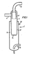
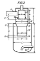
- Figures 1 and 2 are vertical sections of different embodiments of a separator according to the invention.
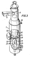
- Figures 3 and 4 are side elevations of further embodiments of the invention.
- all embodiments included the adjustable shutter to restrict the inlet as described in our UK Patent Applications Nos. 2,000,054A and 43043/78 and also a valve upstream of the shutter to control the rate of entry of feed to the vessel.
- the separator is indicated generally by reference numeral 2 and comprises a vessel 4 having an inlet 6 of rectangular cross section disposed tangentially with respect to the vessel 4 to cause incoming feed to form a downwardly spinning vortex of liquid and an upwardly spinning vortex of gas.
- the inlet 6 is controllably variable as described in our co - pending UK Patent Applications Nos. 2,000,054A and 43043/78 to provide a turndown capacity.
- the separator has a vortex finder 8 leading to an outlet pipe 10.
- the separator has a hollow truncated cone 12 of small angle (the angle at the apex of the cone is 3°) to provide a surface for the vortex of liquid.
- the ratio of the diameter of the cone at its lower end to that at its upper end is 0.88.
- a hollow cylinder 12 is provided supported by a truncated cone 11.
- a disengaging chamber 15 is provided by the space between cone 12 and the walls 7 of the lower part of the vessel and an outlet shown for withdrawing gas from the disengaging chamber is provided.
- a baffle in the form of a circular plate 14, the purpose of which is to arrest the vortex of liquid.
- the diameter of the plate is desirably at least 0.75 that of the base of the cone or cylinder and can be up to 1.50.
- Means are provided (not shown) for moving the plate up to down to adjust the size of the gap between the lower end of the cone and the plate to optimise the performance.
- a baffle assembly indicated generally by numeral 29 consisting of six rectangular plates 22, 24, 26, 28, and 32 disposed vertically and radially with respect to the axis of the vessel.
- a curved outlet 16 for the liquid, arranged so that liquid is withdrawn from near the bottom of the vessel to reduce the risk of entrainment of gas in the liquid during discharge.
- a set of straightening vanes may be included in the outlet pipe 10 to eliminate any spinning of the gas.
- the separator has a short conical portion 11 from which is supported a cylinder 12.
- the vortex finder 8 has a flared portion to provide a skirt 9 to reduce the tendency of droplets of liquid on the exterior to be entrained in the gas flowing upwardly into the vortex finder.
- All the embodiments include a liquid level control system 30 (shown only in Figure 4) in which a valve 31 on outlet pipe 16 is controlled by a level controller responsive to the liquid level in the vessel.
- the cyclone separator was a single vessel as illustrated in Figure 2 and the dimensions were as follows:
- the separators described above can operate with feeds which may contain slugs of gas followed by slugs of liquid of up to 20 pipe diameters. They can also operate at rates of throughput which vary by a factor of 10.
- the separators are also suitable for installation at a crude oil gathering centre.
Landscapes
- Engineering & Computer Science (AREA)
- Mining & Mineral Resources (AREA)
- Geology (AREA)
- Life Sciences & Earth Sciences (AREA)
- Fluid Mechanics (AREA)
- Environmental & Geological Engineering (AREA)
- Chemical & Material Sciences (AREA)
- Physics & Mathematics (AREA)
- Chemical Kinetics & Catalysis (AREA)
- General Life Sciences & Earth Sciences (AREA)
- Geochemistry & Mineralogy (AREA)
- Cyclones (AREA)
- Separation Using Semi-Permeable Membranes (AREA)
- Separating Particles In Gases By Inertia (AREA)
Applications Claiming Priority (4)
| Application Number | Priority Date | Filing Date | Title |
|---|---|---|---|
| GB7912806 | 1979-04-11 | ||
| GB7912806 | 1979-04-11 | ||
| GB7918733 | 1979-05-30 | ||
| GB7918733 | 1979-05-30 |
Publications (3)
| Publication Number | Publication Date |
|---|---|
| EP0018168A2 true EP0018168A2 (de) | 1980-10-29 |
| EP0018168A3 EP0018168A3 (en) | 1981-01-07 |
| EP0018168B1 EP0018168B1 (de) | 1984-08-15 |
Family
ID=26271225
Family Applications (1)
| Application Number | Title | Priority Date | Filing Date |
|---|---|---|---|
| EP80301144A Expired EP0018168B1 (de) | 1979-04-11 | 1980-04-10 | Abscheider zur Trennung von Öl und Gas |
Country Status (7)
| Country | Link |
|---|---|
| US (1) | US4596586A (de) |
| EP (1) | EP0018168B1 (de) |
| AU (1) | AU536655B2 (de) |
| CA (1) | CA1136061A (de) |
| DE (1) | DE3068935D1 (de) |
| MX (1) | MX154658A (de) |
| NO (1) | NO152730C (de) |
Cited By (18)
| Publication number | Priority date | Publication date | Assignee | Title |
|---|---|---|---|---|
| US4353719A (en) * | 1981-01-09 | 1982-10-12 | Kennedy Alvin B Jun | Drilling fluid gas and solids removal system |
| US4354852A (en) * | 1981-04-24 | 1982-10-19 | Hydrocarbon Research, Inc. | Phase separation of hydrocarbon liquids using liquid vortex |
| GB2133718A (en) * | 1983-01-21 | 1984-08-01 | Amtrol Inc | Gas-liquid vortex separator-eliminator |
| US4491460A (en) * | 1983-01-31 | 1985-01-01 | Donaldson Company, Inc. | Air cleaner and deflecting intake tube |
| GB2157188A (en) * | 1984-04-12 | 1985-10-23 | Pall Corp | Blood filter |
| US4555253A (en) * | 1983-01-21 | 1985-11-26 | Amtrol, Inc. | Gas-liquid vortex separator-eliminator |
| WO1986003252A1 (en) * | 1984-11-20 | 1986-06-05 | Paladon (Engineering) Limited | Three phase separator |
| EP0155553A3 (en) * | 1984-03-08 | 1987-12-02 | Firma Fullpack Dipl.Brau-Ing. D. Wieland | Device for the treatment of a strong foaming liquid with a gas |
| GB2191424A (en) * | 1985-02-26 | 1987-12-16 | Chevron Res | Gas/liquid separator |
| GB2205512A (en) * | 1987-06-06 | 1988-12-14 | Clean Water Company Limited Th | Vortex separator |
| WO1999025454A1 (en) * | 1997-11-18 | 1999-05-27 | Kvaerner Process Systems A.S. | Separators |
| US7059311B2 (en) | 2004-08-12 | 2006-06-13 | Shiloh Industries, Inc. | Air/oil separating device |
| WO2011149653A3 (en) * | 2010-05-25 | 2012-03-15 | Honeywell International Inc. | Slug mitigation by increasing available surge capacity |
| WO2014066036A3 (en) * | 2012-10-26 | 2014-10-02 | Dow Global Technologies Llc | Hydroclone |
| CN105268214A (zh) * | 2014-06-10 | 2016-01-27 | 横河电机株式会社 | 脱泡装置 |
| WO2018212661A1 (en) * | 2017-05-15 | 2018-11-22 | Aker Solutions As | System and method for fluid processing |
| RU208262U1 (ru) * | 2021-07-16 | 2021-12-13 | Павел Юрьевич Илюшин | Вертикальный сепаратор нефтегазовой смеси |
| CN114570118A (zh) * | 2022-05-06 | 2022-06-03 | 北京石油化工学院 | 一种多级多段分离作用协同集成的管式气液分离器 |
Families Citing this family (52)
| Publication number | Priority date | Publication date | Assignee | Title |
|---|---|---|---|---|
| US4626237A (en) * | 1984-12-10 | 1986-12-02 | Exxon Production Research Co. | Method and apparatus for separating the components of a wellstream |
| GB2179156B (en) * | 1985-08-14 | 1990-08-22 | Ronald Northedge | Flow meters |
| US4650491A (en) * | 1986-02-14 | 1987-03-17 | Pfizer Hospital Products Group, Inc. | Locking mechanism for prosthesis components |
| US4900339A (en) * | 1989-03-20 | 1990-02-13 | Ward David P | Ammonia flow divider |
| US5028318A (en) * | 1989-04-19 | 1991-07-02 | Aeroquip Corporation | Cyclonic system for separating debris particles from fluids |
| US5197509A (en) * | 1990-06-06 | 1993-03-30 | Cheng Dah Y | Laminar flow elbow system and method |
| SE9103824L (sv) * | 1991-12-23 | 1992-11-30 | Kamyr Ab | Saett och cyklonanordning foer att motverka skumbildning |
| US5529084A (en) * | 1994-03-24 | 1996-06-25 | Koch Engineering Company, Inc. | Laminar flow elbow system and method |
| US5584911A (en) * | 1995-06-15 | 1996-12-17 | Jordan Holding Company | Vapor recovery system with cyclonic separator |
| AU3307697A (en) * | 1996-06-21 | 1998-01-07 | Jordan Holding Company | Return circuit for vapor recovery system |
| US5919036A (en) * | 1996-12-02 | 1999-07-06 | O'brien; Alan | Method and apparatus for burning combustible gases |
| US5827357A (en) * | 1997-01-15 | 1998-10-27 | Northland Production Testing Ltd. | Separator and method for separating components of pressurized drilling fluid returns |
| CA2200825C (en) * | 1997-03-24 | 2004-07-13 | Vision Almet Limited | Moisture separator for digester gases and landfill gases and raw natural gases |
| US5931990A (en) * | 1997-12-03 | 1999-08-03 | Coronator | Tank for removing unabsorbed gas from a mixture of unabsorbed gas and liquid |
| US6238572B1 (en) | 1998-07-21 | 2001-05-29 | Clearline Systems, Inc. | Separation tank module for kitchen effluent |
| US6391190B1 (en) | 1999-03-04 | 2002-05-21 | Aec Oil Sands, L.P. | Mechanical deaeration of bituminous froth |
| RU2156638C1 (ru) * | 1999-08-04 | 2000-09-27 | Данченко Анатолий Валентинович | Способ дегазации жидких масел и устройство для дегазации жидких масел |
| US6461414B1 (en) * | 1999-10-29 | 2002-10-08 | Baker Hughes Incorporated | Foam monitoring and control system |
| NO312138B1 (no) | 2000-05-04 | 2002-03-25 | Kongsberg Offshore As | Fremgangsmåte og sjöbasert installasjon for håndtering og behandling av flerfraksjonshydrokarboner til sjös |
| US6632352B2 (en) | 2001-07-11 | 2003-10-14 | Nursery Pro, Inc. | Multi-stage filter |
| US20040197622A1 (en) * | 2003-04-04 | 2004-10-07 | Texaco Inc. | Method and apparatus for separating liquid from a gas stream |
| GB0410961D0 (en) * | 2004-05-17 | 2004-06-16 | Caltec Ltd | A separation system for handling and boosting the production of heavy oil |
| MY147883A (en) * | 2004-12-30 | 2013-01-31 | Shell Int Research | Cyclonic separator and method for degassing a fluid mixture |
| EA014604B1 (ru) | 2006-06-29 | 2010-12-30 | Шелл Интернэшнл Рисерч Маатсхаппий Б.В. | Циклонный сепаратор, предназначенный для дегазации жидкости, и способ дегазации жидкой смеси |
| TR200903943A2 (tr) * | 2009-05-22 | 2010-06-21 | Durmazlar Maki̇na Sanayi̇ Ve Ti̇caret Anoni̇m Şi̇rketi̇ | Bir siklon ayırıcı |
| IT1397618B1 (it) | 2009-06-26 | 2013-01-18 | Eni Spa | Sistema di separazione compatto inerziale gas-liquido |
| JP4695215B1 (ja) | 2010-03-05 | 2011-06-08 | 独立行政法人石油天然ガス・金属鉱物資源機構 | 気液分離器及び流量計測装置 |
| US8960450B2 (en) | 2010-12-08 | 2015-02-24 | Dow Global Technologies Llc | Apparatus and method for implementing hydroclone based fluid filtration systems with extensible isolated filter stages |
| JP4688974B1 (ja) | 2010-12-13 | 2011-05-25 | 独立行政法人石油天然ガス・金属鉱物資源機構 | バッチ式多相流量測定装置及び流量計測方法 |
| US9050610B2 (en) | 2012-05-17 | 2015-06-09 | Dow Global Technologies Llc | Hydroclone with inlet flow shield |
| US9186604B1 (en) | 2012-05-31 | 2015-11-17 | Dow Global Technologies Llc | Hydroclone with vortex flow barrier |
| CN105080736A (zh) * | 2014-05-21 | 2015-11-25 | 德昌电机(深圳)有限公司 | 分离装置 |
| US9101859B2 (en) | 2012-06-01 | 2015-08-11 | Dow Global Technologies Llc | Cross-flow filtration system including particulate settling zone |
| US9328856B2 (en) * | 2013-01-29 | 2016-05-03 | Cameron International Corporation | Use of pressure reduction devices for improving downstream oil-and-water separation |
| US9248456B2 (en) * | 2013-02-05 | 2016-02-02 | Claude Laval Corporation | Centrifugal separator with extended post |
| US20140251140A1 (en) * | 2013-03-06 | 2014-09-11 | Cameron Solutions, Inc. | Methods To Reduce Gas Carry-Under For Cyclonic Separators |
| US8979982B2 (en) | 2013-05-01 | 2015-03-17 | Jordan Technologies, Llc | Negative pressure vapor recovery system |
| CN105960286B (zh) | 2013-12-05 | 2019-01-29 | 陶氏环球技术有限责任公司 | 具有改进的清洁组合件的水力旋流器 |
| CA2971175C (en) | 2014-12-18 | 2024-01-23 | Dow Global Technologies Llc | Cylindrical filter screen with tensioning mechanism |
| ITUB20152444A1 (it) * | 2015-07-23 | 2017-01-23 | Palmac Ing Palmisano S R L | Camera di sedimentazione a doppia camera a flussi separati |
| NO343290B1 (en) * | 2015-11-09 | 2019-01-21 | Fmc Kongsberg Subsea As | Solids separator |
| JP2018199116A (ja) * | 2017-05-30 | 2018-12-20 | マイクロゼロ株式会社 | エアーセパレータおよび気液分離装置 |
| US10918973B2 (en) * | 2017-11-02 | 2021-02-16 | Hydac Technology Corporation | Device for medium separation |
| US11161058B2 (en) | 2019-12-31 | 2021-11-02 | Saudi Arabian Oil Company | Fluid separation systems for oil and gas applications |
| US11090581B1 (en) | 2020-06-25 | 2021-08-17 | Saudi Arabian Oil Company | Oil and water separation |
| US11314266B2 (en) | 2020-07-08 | 2022-04-26 | Saudi Arabian Oil Company | Flow management systems and related methods for oil and gas applications |
| US11802645B2 (en) | 2020-07-08 | 2023-10-31 | Saudi Arabian Oil Company | Flow management systems and related methods for oil and gas applications |
| US11294401B2 (en) | 2020-07-08 | 2022-04-05 | Saudi Arabian Oil Company | Flow management systems and related methods for oil and gas applications |
| US11256273B2 (en) | 2020-07-08 | 2022-02-22 | Saudi Arabian Oil Company | Flow management systems and related methods for oil and gas applications |
| US11131158B1 (en) | 2020-07-08 | 2021-09-28 | Saudi Arabian Oil Company | Flow management systems and related methods for oil and gas applications |
| US11274501B2 (en) | 2020-07-08 | 2022-03-15 | Saudi Arabian Oil Company | Flow management systems and related methods for oil and gas applications |
| US20230384133A1 (en) * | 2022-05-31 | 2023-11-30 | NeoTek Energy, Inc. | Multiphase Measurement System With Electromagnetic Water Cut Meter And Waxy Solids Control Systems |
Family Cites Families (21)
| Publication number | Priority date | Publication date | Assignee | Title |
|---|---|---|---|---|
| US2010435A (en) * | 1933-04-08 | 1935-08-06 | Standard Oil Dev Co | Filtration apparatus and method |
| US2781910A (en) * | 1951-11-30 | 1957-02-19 | Stamicarbon | Process of thickening suspensions or emulsions |
| GB796886A (en) * | 1955-01-20 | 1958-06-18 | Walter Jordan | Gas separator for fuel decanting installations |
| US3163508A (en) * | 1960-09-07 | 1964-12-29 | Smith Paper Mills Ltd Howard | Method and apparatus for separating gas from liquid rich foams or liquids containing entrained air |
| US3288300A (en) * | 1962-02-14 | 1966-11-29 | Bauer Bros Co | Centrifugal cleaner |
| US3204772A (en) * | 1962-06-21 | 1965-09-07 | Pacific Pumping Company | Sand separator |
| US3259246A (en) * | 1963-05-29 | 1966-07-05 | Dorr Oliver Inc | Hydrocyclones |
| US3331193A (en) * | 1964-03-23 | 1967-07-18 | Bauer Bros Co | Cyclonic separator |
| DE1544111A1 (de) * | 1966-06-25 | 1970-03-12 | Hans Richter | Zentrifugal-Wasser- und OElabscheider fuer Dampf,Druckluft und Druckgase |
| DE1301796B (de) * | 1967-06-13 | 1969-08-28 | Grubbens & Co Aktiebolag | Hydrozyklon |
| CH484686A (de) * | 1967-06-16 | 1970-01-31 | Escher Wyss Ag | Zyklon zum Abschneiden von Gasen aus Flüssigkeits-Gas-Gemischen |
| US3488927A (en) * | 1967-10-23 | 1970-01-13 | Shell Oil Co | Gas-liquid cyclone separator |
| US3481118A (en) * | 1968-04-22 | 1969-12-02 | Porta Test Mfg | Cyclone separator |
| US3512651A (en) * | 1968-09-06 | 1970-05-19 | Laval Claude C | Device for removing solid particles from liquid |
| US3684093A (en) * | 1969-08-13 | 1972-08-15 | Ashizawa Iron Works Co Ltd | Method and apparatus for separating particles from particle-laden fluid |
| US3668825A (en) * | 1969-08-28 | 1972-06-13 | Nat Dust Collector Corp | Method and apparatus for determining the difficulty of removing pollutants by wet scrubbing action |
| US3802570A (en) * | 1972-10-25 | 1974-04-09 | M Dehne | Cyclone separator |
| US3959139A (en) * | 1974-09-16 | 1976-05-25 | Filter Tech, Inc. | Liquid purification system |
| US4072481A (en) * | 1976-04-09 | 1978-02-07 | Laval Claude C | Device for separating multiple phase fluid systems according to the relative specific gravities of the phase |
| GB2000054B (en) * | 1977-06-23 | 1982-01-20 | British Petroleum Co Limited | Separator |
| GB2035150B (en) * | 1978-06-22 | 1983-03-23 | British Petroleum Co | Cyclone separator |
-
1980
- 1980-04-09 AU AU57262/80A patent/AU536655B2/en not_active Ceased
- 1980-04-10 DE DE8080301144T patent/DE3068935D1/de not_active Expired
- 1980-04-10 EP EP80301144A patent/EP0018168B1/de not_active Expired
- 1980-04-10 NO NO801039A patent/NO152730C/no unknown
- 1980-04-11 CA CA000349612A patent/CA1136061A/en not_active Expired
- 1980-04-11 MX MX181954A patent/MX154658A/es unknown
-
1981
- 1981-11-04 US US06/318,160 patent/US4596586A/en not_active Expired - Fee Related
Cited By (29)
| Publication number | Priority date | Publication date | Assignee | Title |
|---|---|---|---|---|
| US4353719A (en) * | 1981-01-09 | 1982-10-12 | Kennedy Alvin B Jun | Drilling fluid gas and solids removal system |
| US4354852A (en) * | 1981-04-24 | 1982-10-19 | Hydrocarbon Research, Inc. | Phase separation of hydrocarbon liquids using liquid vortex |
| US4555253A (en) * | 1983-01-21 | 1985-11-26 | Amtrol, Inc. | Gas-liquid vortex separator-eliminator |
| US4475932A (en) * | 1983-01-21 | 1984-10-09 | Amtrol Inc. | Gas-liquid vortex separator-eliminator |
| GB2133718A (en) * | 1983-01-21 | 1984-08-01 | Amtrol Inc | Gas-liquid vortex separator-eliminator |
| US4491460A (en) * | 1983-01-31 | 1985-01-01 | Donaldson Company, Inc. | Air cleaner and deflecting intake tube |
| EP0155553A3 (en) * | 1984-03-08 | 1987-12-02 | Firma Fullpack Dipl.Brau-Ing. D. Wieland | Device for the treatment of a strong foaming liquid with a gas |
| GB2157188A (en) * | 1984-04-12 | 1985-10-23 | Pall Corp | Blood filter |
| WO1986003252A1 (en) * | 1984-11-20 | 1986-06-05 | Paladon (Engineering) Limited | Three phase separator |
| GB2178977A (en) * | 1984-11-20 | 1987-02-25 | Paladon | Three phase separator |
| GB2191424A (en) * | 1985-02-26 | 1987-12-16 | Chevron Res | Gas/liquid separator |
| GB2191424B (en) * | 1985-02-26 | 1990-06-20 | Chevron Res | Gas/liquid separator |
| GB2205512A (en) * | 1987-06-06 | 1988-12-14 | Clean Water Company Limited Th | Vortex separator |
| GB2205512B (en) * | 1987-06-06 | 1991-02-13 | Clean Water Company Limited Th | Improvements in or relating to separators |
| WO1999025454A1 (en) * | 1997-11-18 | 1999-05-27 | Kvaerner Process Systems A.S. | Separators |
| US6409808B1 (en) | 1997-11-18 | 2002-06-25 | Kvaerner Process Systems A.S. | Separators |
| US7059311B2 (en) | 2004-08-12 | 2006-06-13 | Shiloh Industries, Inc. | Air/oil separating device |
| WO2011149653A3 (en) * | 2010-05-25 | 2012-03-15 | Honeywell International Inc. | Slug mitigation by increasing available surge capacity |
| WO2014066036A3 (en) * | 2012-10-26 | 2014-10-02 | Dow Global Technologies Llc | Hydroclone |
| US20150224517A1 (en) * | 2012-10-26 | 2015-08-13 | Filmtec Corporation | Hydroclone |
| US9192946B2 (en) * | 2012-10-26 | 2015-11-24 | Dow Global Technologies Llc | Hydroclone |
| CN105268214A (zh) * | 2014-06-10 | 2016-01-27 | 横河电机株式会社 | 脱泡装置 |
| CN105268214B (zh) * | 2014-06-10 | 2018-02-13 | 横河电机株式会社 | 脱泡装置 |
| WO2018212661A1 (en) * | 2017-05-15 | 2018-11-22 | Aker Solutions As | System and method for fluid processing |
| GB2578012A (en) * | 2017-05-15 | 2020-04-15 | Aker Solutions As | System and method for fluid processing |
| US11071930B2 (en) | 2017-05-15 | 2021-07-27 | Aker Solutions As | System and method for fluid processing |
| GB2578012B (en) * | 2017-05-15 | 2022-06-15 | Aker Solutions As | System and method for fluid processing |
| RU208262U1 (ru) * | 2021-07-16 | 2021-12-13 | Павел Юрьевич Илюшин | Вертикальный сепаратор нефтегазовой смеси |
| CN114570118A (zh) * | 2022-05-06 | 2022-06-03 | 北京石油化工学院 | 一种多级多段分离作用协同集成的管式气液分离器 |
Also Published As
| Publication number | Publication date |
|---|---|
| US4596586A (en) | 1986-06-24 |
| EP0018168B1 (de) | 1984-08-15 |
| AU536655B2 (en) | 1984-05-17 |
| NO152730C (no) | 1985-11-13 |
| EP0018168A3 (en) | 1981-01-07 |
| NO801039L (no) | 1980-10-13 |
| NO152730B (no) | 1985-08-05 |
| CA1136061A (en) | 1982-11-23 |
| AU5726280A (en) | 1980-10-16 |
| DE3068935D1 (en) | 1984-09-20 |
| MX154658A (es) | 1987-11-13 |
Similar Documents
| Publication | Publication Date | Title |
|---|---|---|
| EP0018168B1 (de) | Abscheider zur Trennung von Öl und Gas | |
| EP0024148B1 (de) | Abscheider für Öl, Gas und Wasser | |
| US4369047A (en) | Gas separation from crude oil | |
| US7931719B2 (en) | Revolution vortex tube gas/liquids separator | |
| GB2035150A (en) | Cyclone separator | |
| US4539023A (en) | Horizontal gas and liquid separator | |
| US7594942B2 (en) | Gas/liquid separator | |
| CN101330955B (zh) | 用于分离包括水、油以及气体的流体的分离罐、该分离罐的应用以及用于分离包括水、油以及气体的流体的方法 | |
| US5302294A (en) | Separation system employing degassing separators and hydroglyclones | |
| US5507858A (en) | Liquid/gas separator and slug flow eliminator and process for use | |
| CN101330953B (zh) | 用于分离井产流体的分离罐及分离方法 | |
| US4132652A (en) | Slotted baffle for use in separating oil-water mixtures | |
| US4015960A (en) | Centrifugal separator for separating entrained liquid from a stream of liquid-bearing gases | |
| US3212232A (en) | Method and apparatus for fluid separation | |
| NZ215346A (en) | Separating a liquid from a gas in a column | |
| JP2002537968A (ja) | 三相分離器 | |
| KR20180096681A (ko) | 플로팅 제조 저장 및 하역 설비의 원유 저장 탱크 내의 원유를 탈수하기 위한 정전기 기술 시스템 및 방법 | |
| US3362136A (en) | Apparatus for degassing fluids | |
| CA2018251C (en) | Device for separating liquids and/or solids from a high-pressure gas stream | |
| RU2135886C1 (ru) | Способ и устройство для предварительного сброса воды в системах сбора продукции нефтедобывающих скважин | |
| US5458777A (en) | Distributor for liquid separator | |
| RU2077918C1 (ru) | Аппарат для обезвоживания нефти | |
| US3873283A (en) | Vapor-liquid separator | |
| US3246451A (en) | Liquid distribution system | |
| WO1986003252A1 (en) | Three phase separator |
Legal Events
| Date | Code | Title | Description |
|---|---|---|---|
| PUAI | Public reference made under article 153(3) epc to a published international application that has entered the european phase |
Free format text: ORIGINAL CODE: 0009012 |
|
| AK | Designated contracting states |
Designated state(s): DE FR GB IT NL |
|
| PUAL | Search report despatched |
Free format text: ORIGINAL CODE: 0009013 |
|
| AK | Designated contracting states |
Designated state(s): DE FR GB IT NL |
|
| 17P | Request for examination filed |
Effective date: 19810210 |
|
| RAP1 | Party data changed (applicant data changed or rights of an application transferred) |
Owner name: THE BRITISH PETROLEUM COMPANY P.L.C. |
|
| ITF | It: translation for a ep patent filed | ||
| GRAA | (expected) grant |
Free format text: ORIGINAL CODE: 0009210 |
|
| AK | Designated contracting states |
Designated state(s): DE FR GB IT NL |
|
| REF | Corresponds to: |
Ref document number: 3068935 Country of ref document: DE Date of ref document: 19840920 |
|
| ET | Fr: translation filed | ||
| PLBE | No opposition filed within time limit |
Free format text: ORIGINAL CODE: 0009261 |
|
| STAA | Information on the status of an ep patent application or granted ep patent |
Free format text: STATUS: NO OPPOSITION FILED WITHIN TIME LIMIT |
|
| 26N | No opposition filed | ||
| PGFP | Annual fee paid to national office [announced via postgrant information from national office to epo] |
Ref country code: NL Payment date: 19870430 Year of fee payment: 8 |
|
| ITTA | It: last paid annual fee | ||
| PG25 | Lapsed in a contracting state [announced via postgrant information from national office to epo] |
Ref country code: NL Effective date: 19881101 |
|
| NLV4 | Nl: lapsed or anulled due to non-payment of the annual fee | ||
| PG25 | Lapsed in a contracting state [announced via postgrant information from national office to epo] |
Ref country code: DE Effective date: 19900103 |
|
| PGFP | Annual fee paid to national office [announced via postgrant information from national office to epo] |
Ref country code: FR Payment date: 19950221 Year of fee payment: 16 |
|
| PGFP | Annual fee paid to national office [announced via postgrant information from national office to epo] |
Ref country code: GB Payment date: 19950327 Year of fee payment: 16 |
|
| PG25 | Lapsed in a contracting state [announced via postgrant information from national office to epo] |
Ref country code: GB Effective date: 19960410 |
|
| GBPC | Gb: european patent ceased through non-payment of renewal fee |
Effective date: 19960410 |
|
| PG25 | Lapsed in a contracting state [announced via postgrant information from national office to epo] |
Ref country code: FR Effective date: 19961227 |
|
| REG | Reference to a national code |
Ref country code: FR Ref legal event code: ST |